My chosen object is a footstool. It has wooden legs and structure. The seat park is upholstered in grey fabric and foam. The elements are held together with metal screws. The overall dimensions are 480mm long by 400mm wide by 440mm high.
It can be used as a footrest or a seat. In my house it is usually either a footrest or a cat bed.
Reflection:
I decided to make a drawing in CAD, as I felt I needed to practice it some more. Plotting proved difficult again but with some help of online tutorials I got over it. Next exercise should go a little faster as scaling the objects will be at a touch of a button. I enjoyed measuring the object and all its elements. Section was a bit challenging as I don’t actually know what this footstool would look like sliced in half, I had to employ my imagination and use my common sense.
Here is my CAD drawing in PDF, so finer details can be seen.
How do you think ergonomic and anthropometric design, and scale, have been explored in the 2013 project Kroppsrom (Corporeal room) at the National Museum of Architecture by Atelier Oslo? Reflect on your responses to the project in your learning log.
I think the designers explored the anthropometric data of the average human figure and designed the space around them. One of the resources mentioned that the space was supposed to make people move in a way they would not expect, and create the experience through the activity, as well as simple, peaceful and gently lit interior.
I imagine Atelier Oslo drew the human figures as pictured in the data images and made the space flow from one set of dimensions to another and so on. I can sort of see this process in my imagination, but it is quite hard to describe it, but I’ll try anyway. A 3D animation of an opening being created in the solid mass. The solid mass is surrounding (and filling) the human forms being carved out. As the corridors and caverns are created, the human figures remain – they aren’t carved out with the solid mass that they are contained within. As if the figures are in a different layer to the mass. The whole process is smooth and flows easily.
Fig. 1 Body measurements
Considering the process of creation of such an interesting, unusual space is a great activity. I wonder If I am at least a little bit correct in my guessing on how the designers idea started. Thinking about it got my imagination going. I often wonder about hows and whys, it was an enjoyable exercise.
I consider my recent feedback to be a very positive one, I received a lot of praise from my tutor with only a few things to reconsider.
My tutor noted that my skills and confidence improved throughout unit 5. She also complimented me on thoroughness, attention of detail and amount of work I put in.
My observation that software knowledge is a tool to enable creativity was correct.
My tutor noticed that I took on board her previous comment about reworking a design which resulted in great progress.
My research was in depth and on topic. I observed relevant points and described them in a way that my tutor approved. Acknowledging the view of my pavilion from the racecourse showed my consideration of the design from all aspects.
My tutor noticed that certain examples from my precedents feed into my design, but I had practical aspects of my location in mind. My tutor said it was the point of the precedent research: to inspire my design and it happened in this case. I got a ‘well done for speaking to suppliers’ as they are an invaluable source of knowledge on materials and their processing.
My tutor especially liked my cardboard pavilion model with scale people. She mentioned that making a quick model helps understand the design better, especially if I am stuck on drawing phase. Model gives 3D dimensions, and I can physically see how things go together and look from different aspects. Making my final model certainly helped me to understand what I want and what I do not want in my design and really aided my understanding of side elevation of my pavilion.
My software skills are improving (Adobe fresco and photoshop) and continued experimenting with them is encouraged. My tutor particularly liked my pavilion drawing that I did for materiality exercise. Sadly, I lost some of the designs elegance when I was making dimensions decisions as I was worried about sturdiness of the structure. It seems that as I am improving with creative software my creativity improves as well. Additional drawing exercises (such as life drawing) will help me to ‘see’ as drawing is about the ability to observe. My tutor noted that adobe fresco seems to be working for me. I think it is because of ease of selecting colours exactly as intended and erasing errors does not leave ugly marks as it would on the sheet of paper. Also drawing over images (such as a picture of my model for amended visual) helps me get drawings more correct. Therefore, the outcomes seem more elegant. I continue discovering new features in the program as I go along. I really enjoy digital drawing, more than by hand.
I received some pointers for the future. When designing the public space, I should include all users (e.g., incorporate wheelchair turning point, make sure my entrance is wide enough and seating at correct height). Now I know minimum wheelchair turning circle has diameter of 1500mm. Internal diameter of the bottom ring is 1600mm in my design, and it is a little tight, especially if we consider another user (or a bench) that may be inside. My tutor made a comment about my seating being too high, but that was intentional, like ‘lean on’ benches we see at bus stops. I did not feel there was enough space in the interior to have a bench, also people seating down take even more space than standing/ leaning. It all must be reconsidered as I am not sure if aging population will be comfortable leaning back on something that is not next to a secure wall. The point of this bench was so people could lean on it and gaze upwards while inside my pavilion.
My technical drawings start to look and feel as professional drawings.
I was reminded to add ground line to elevations (so they are not floating in space). My tutor also advised me to annotate the technical drawings. There is plenty of space around and people rarely look at the title block, so I included some additional information and added them to my section drawings.
My tutor suggested to try and take photos of the interior of my model, to show users interior view. It was a little awkward to get the camera in but not impossible. What a great piece of advice!
My tutor said that she enjoyed my final visual, but my site photo choice was not the best as the red bin was stealing the attention. I redrew my pavilion from different perspective (using adobe fresco over a photo of my model) making the beams more slender and placed it on a different photo from my previous site research. I absolutely agree with my tutor, this visual is better at ‘selling’ the design.
My tutor said my level of reflection is ‘really good as it shows my critical and measured approach’. It is great that I was already suggesting alternative designs when I was not too happy with all aspects of my design. I had also been told to not be too hard on myself, as I am just starting my learning journey.
My tutor mentioned I correctly reflected on jumping back and forth between tasks in design process, she said I will experience it again in next part of the course. I am excited to be starting next unit soon.
Part 5, finally finished. It was the toughest so far. Because it was hard, I learnt a lot. For example, doing each part of the design once is not enough. I should have allowed more time and repeat some parts of the process. At each step you discover that you need to redo something at previous step. I feel my design is unfinished. If I were to have my pavilion built, I would have to go back and refine the details (such as wire placements and perhaps review wire attachments and the shape of the entrance). I also could have drawn the rings as bent slices of wood. I realise that the rings could not be infinite circles, yet I did not include the arch connecting detail in any of my drawings. There are other mistakes I noticed that I mentioned in my blog. Yet it took so long to draw all these details. Nevertheless, I am pleased with the outcome. I am very new to this, and my design skills fell victim of my imagination. I think it is brilliant I came out with a difficult shape; I just need to improve my drawing skills so next time there will be no shortfalls. On top of that I need to improve my time management skills and plan better in future.
I really like how wires on technical drawing on screen convey ‘moire’ effect I had in mind. It would look even better in shiny stainless steel in real life.
One of the most difficult and satisfying tasks in this exercise was drawing the top rings in side elevation. It took some time to work out what it should look like.
The entrance in plan view was also really tricky. Initially it looked like this:
I realised that I never included the material of legs – it’s stainless steel.
I’m afraid I encountered a ‘design fail’ in my technical drawing. Side elevation wires have a gap that is not attractive. To fix that I would need to change the design of the entrance and/ or positioning of the wires. Unfortunately time restraints did not allow it. I feel I should have discovered it at previous exercise (design development). Someone once said that design development can go forever and I think I have a perfect example here. If I had a time restraint like this in ‘real’ design life, I would probably submit what I have to the client and propose the following versions around the entrance.
I particularly like version 2. The entrance is circular in the top and goes straight down the sides (rather than narrowing like in original design). I think wires in ray like position would give even better moire effect as well.
Another solution would be to do what I did in model building. I attached the wires to the back of the entrance and therefore they went ‘lower’ on the frame.
During the process of technical drawing I decided that some of the wires attachments around the entrance would be different to the rest of them. I opted for a different mount, a vertical type, that would have to be installed at the same angle that the wire meets the frame.
It’s all very complicated and I feel that more research and development work is needed.
I also realise I didn’t do all wires as I should have. I.e. I didn’t use guidelines to place them on relevant spots on the frame. Instead I just spread them evenly in elevation views even though it would not look like that. They would be closer together towards the edges of the view and further apart in the centre of the view. It took such a long time to draw and position all the wires. I think I spent around 40 hours on technical drawing task. I was thinking lines, I was dreaming lines… I kept thinking of contextual study about lines from previous exercise. I was very grateful for the existence of guidelines, without them this task would have been impossible.
I feel I should have started with ‘rough’ technical drawing, followed up by scale model building and then refined technical drawing.
I think in design work you would normally jump back and forth between such tasks as you refine the design. Here I did them once and in specific order.
I built my model in scale 1:20. I used model foam sheets, wood sticks, white thread, dowels sharpened with pencil sharpener. At first I was using removable glue dots to ensure right proportions and stability of the frame. Later on I used super glue to make it more rigid. I painted all wood elements with white spray paint.
I imported some of my iPad people drawings on to cad and scaled them to be approx 1650mm high, then I printed them in scale 1:20 and attached to pieces of cardboard.
The process of building this model was not easy. I chose such a complicated shape! I had to research model building materials, tried balsa wood (difficult to cut neat circles without specialist tools) and metal wire for wires (difficult to position without piercing the foam).
I’m happy with my model, despite it being a bit rough around the edges. I can think of two ways my model could have been neater:
1. Creating a 3d version of it in software and the printing it on a 3D printer. This option also wouldn’t inform me how each piece relates to other pieces.
2. Getting specialist model building electric tools and building the whole frame from wood.
Both of these options were outside of my already overstretched budget.
I believe I started this exercise when creating my drawing for materiality sheet. I opened one of my previous hand drawings in Adobe Fresco app and started drawing on top of it. Here is the process: (Fig. 1 – fig. 6)
Fig. 1 – fig. 6
As in this exercise I am meant to look at function and whether the size is big enough I had to work out my initial design into maximum dimensions required. So I looked at my brief again and worked out I would like the biggest circle diameter to be 3300mm which fits within 9m2. Then I worked out my head room in the doorway to be 2200mm in the tallest point. It is quite tall for the door but I need to have in mind that it will be lower to the sides.
I set maximum height at 5900mm giving me 100mm space just in case I later decide to create base for the pavilion.
I drew these dimensions in cad, including 200mm beam thickness for reference. I then saved it as a .jpg and imported to a drawing app on my iPad.
I drew and experimented with the front elevation view of my pavilion. I even created one with background (by drawing over a photo of relevant view) and one with shadow (even though usual elevation drawings would not include it). (Fig. 7 – fig. 26)
Fig. 7 – fig. 26
Then it was time to move to side elevation. (Fig. 27 – fig. 30)
It was really tricky as the top ‘ring’ is at an angle (I’ll let cad tell me later what angle this is) therefore it cannot be just flat rectangle in side view. The entrance was also really tricky. As I’m typing it up I can see that side view with entrance facing left contains quite a few errors. Such as the beam not reaching to ring in correct place and top ring positioning and angle in general.
That is something I’ll correct when completing technical drawing for my design.
I think I best work out details of that when drawing technical in cad later on.
Fig. 27 – fig. 30
Then I moved to drawing back elevation. It was simple to do by drawing over front elevation with only major difference being the angle of top circle and front/back reversed (Fig. 31 – fig. 32)
Fig. 31 – fig. 32
After that I needed to workout my rings diameters. I already knew that the largest, middle ring will have external diameter of 3300mm and internal 2900mm. I needed to work out other diameters.
I used the image of front elevation drawing with visible cad guidelines. I cropped it as close to external rectangle of guidelines and then inserted the image into cad. I then resized the image to fit into a 3300 x 5900mm box. From this point I was able to roughly (but still fairly accurately) work out my other rings diameters by drawing and measuring lines on them.
After that I was able to place the rings on my floor plan drawing. I centred them in the same spot (for even weight distribution and stability of my structure). I’m not sure if I should have pictured top ring (smallest one) as a slight oval because it’s angled. I find it really confusing. I can use the similar way later in CAD (or even by hand) to work out the angles in my pavilion. At this point I’m starting to think that it may be easier to build a model in cad (or perhaps real life model will help me enough) (Fig. 33)
Fig. 33
Drawing the entrance in plan view has been quite tricky, a semi ring at an angle! I think oval represents it better (Fig. 34 – 35)
Fig. 34 – 35
The lowest ring (middle one on the plan) will be at knee level and will be the most space restricting feature. I worked out its internal diameter at approximately 1600mm. It took me a some time to work out if it is enough to move around. In the end I measured my outstretched arms span and it is almost the same. So I was able to imagine that it would be enough space at knee level for two people. The place will feel roomier than that as the diameter widens until it reaches 2900mm internally at the largest ring level which is way above average eye line. I am not sure if I should include any seating. Perhaps a small two person bench opposite the entrance (if any).
I have been doing a lot of thinking about how my pavilion will be put together. I called Honeysuckle Bottom Sawmill and they said you cannot bend thick pieces of wood and that they don’t provide curved braces (despite their website saying otherwise).
After this news I was thinking of other ways of creating wooden circles for my structure. I found a local furniture restoration company and I spoke to the owner who has wealth of experience in steam bending wood.
He advised me that it is not possible to bend thick pieces of timber. For my thickness of 200mm x 200mm he would slice them lengthways into 1mm slices and then steam bend and then laminate them together. I asked about drilling and attaching things to the laminated side (top being plane of wood, side where you see slices). I found out it should not be a problem.
He also said that oak is not the best choice for bending and that ash is much more suitable for this purpose. I decided to change my wood choice to ash following his advice.
I am a little worried about the context. I selected oak for reasons specified in my Materiality sheet and gave all the reasons why… Ash is a local tree, I have one (according to a tree surgeon) at the bottom of my garden…
In late 2020 I needed to make a drawing for our carpenter to build these boxes at work. Normally I would just give him one but we need them daily and they started to fall apart. So I decided to practice my new skills and draw what he needs to do.
This along with photos of the old box were explanatory enough for him to build them to my specification.
Peckham Box hand drawings
The images above are of final version. After I gave the contractor the initial drawing, I was asked what is the error margin. I did it with comments on maximum an minimum dimensions that were important for the design to work (I needed to measure the space in storage for these boxes and the jewellery pads to ascertain this). In the mean time I created CAD drawing based on one of the former measurements (just for fun and practice of it).
Today I was trying to work out how to create and insert title box, I decided to work on my old Peckham Box drawing. Here it is, a CAD drawing with title box.
Peckham box CAD drawing with title box
Here is what the old box looks like:
I am still awaiting new boxes for Peckham, in the meantime had some built for another shop. I was pleased my drawings were sufficient to make something.
Oak – durable and beautiful wood. It refers to local area. There are English oaks growing in local woods. According to Woodland Trust English Oak is ‘the 2nd most common tree variety in the UK and a national symbol of strength.’ I would like to use this traditional material as a nod to the local aging community, who will hopefully appreciate its nobility. The wood can be used for outside projects, and it will be very durable if it is properly treated. I would like to treat the oak frame with a clear, UV protecting oil that will show of the natural colour and pattern of the wood. I presume I will have to choose fresh sawn oak (also called ‘green). It will need to be weathered for 6 weeks before applying oil. I would like my structure to be sustainable and durable so the treatment will need to be repeated periodically.
I found a local supplier called Honeysuckle Bottom Sawmill (http://www.surrey-oak.com/) who supply the wood and bespoke curved braces to curve the timber to project specifications. Their products are sustainably and locally sourced. They even supplied wood to film sets.
Fig. 1 Shaped or curved beams
Stainless steel – an alloy composing of chromium and other metals. Chromium reacts with oxygen creating a protective film. Stainless steel is strong, low maintenance, corrosion resistant, sustainable, recyclable (does not deteriorate through recycling), aesthetic and functional. I chose it for its appearance and suitability for an outdoor project.
The wires are simply surface mounts and balustrade wires. They are made to measure and supplied by S3i Group (located in the UK). The ball and socket design allows up to 42 degrees angle.
Fig. 2 Surface Mount Balustrade Wire
Fig. 3 Balustrade wire passing through an intermediate post.
The components I used – wood and metal wire are a high-end nod to farm fencing. It has a loose connection with horses on Epsom Downs and the fact the local area used to be a farmland not so long ago. The warmth of natural oak should provide comfort for users and the wires add interest without spoiling the view.
My tutor suggested to practice drawing people. I felt particularly inspired after recent oca life drawing session. I also wanted to experiment more with new drawing ‘gear’ I got recently.
I downloaded an image of female body proportions, made it less opaque and drew over it in another layer. I believe if I keep drawing this way I will get the hang of the proportions. Hands and feet are still very tricky, but the guides helped a lot. Third figure, at a slight angle seems to be the most useful for interior design visualisations. I realise this body type may not be most representative, or inclusive, but I’ll get to those later, when I understand proportions better.
I also watched ‘Life drawing live’ on bbc catch up and attempted the last pose (19 mins). Below is my brave attempt.
I completed my drawings using automatic 0.9 pencil, HB. I just love how the pencil glides on paper.
I looked at my drawings from previous exercise and decided to go in that direction. First, I played with the shape of the entrance (Fig. 1).
Fig. 1
Then using tracing paper I redrew them with shaded entrance option, I liked rounded option most and the bigger drawing was my last drawing on this page. (Fig. 2)
Fig. 2
I quite like the rounded, shaded entrance but after drawing it in side elevation I did not like it as much (Fig. 3).
Fig. 3
Using tracing paper, I drew the shape again, but this time with more simple entrance (fig. 4). I felt like the shape of my pavilion is somehow inspired by ‘Gherkin’ building in London.
Fig. 4
As much as I was happy with proportions and aesthetics of my design I kept worrying that for it to be translucent and light it would have to be made either of glass (heavy and expensive) or pvc (unsustainable and also pricey). Also, I was afraid that on a warm day it would turn into a ‘glass house’ despite many gaps and opening in the roof.
It took me a while to come up with the next design (Fig. 5 & 6). Funnily enough it was Peckham Library pods that inspired me. The three legs and rounded shape are ‘borrowed’ from there. I have not decided what material it will be yet. There are some options that I will explore further in next exercise. Using string as in Oasis Pavilion may be an option, I found that interior very peaceful.
Fig. 5
Fig. 6
I loved using tracing paper in this exercise. It made it quite easy to repeat the proportions that I wanted to keep.
Fig. 7 – Fig. 11
Lastly, I decided to photograph my model with some scale figures (Fig. 12). As ‘tried them on’ I realised the supporting columns are too high, so I shortened them. Now sadly the entrance is a little lower than I would have liked, but this is just my first model and I think it shows my idea well.
Fig. 12
To me this whole task was the most difficult so far. It is hard to think of the design but only concentrate on one aspect of it. I keep thinking about the materials, the brief does not specify whether it will be a permanent or temporary structure… We also have no budget (which may be a good thing at this stage). It was interesting to see how I came from my first drawing in Exercise 2.3 (https://aggie.video.blog/wp-content/uploads/2021/01/fig.-1.jpeg) to this model.
I realised that shape was not practical for my pavilion. The gaps on the sides would take too much of the maximum 9m2 footprint, so usable interior space would be too small. I do not consider creating this model a waste of time as it inspired me further and I started ‘doodling’ some ideas.
Fig. 6 – 7. Doodle 1 – 2
The idea is a rounded structure on an oval shaped plan. The structure narrows as it goes up, with a large circular opening in the roof and gaps between sheer components of the walls. The oval shape refers to the Tattenham corner sharp bend in the racecourse, the large opening in the roof is inspired by James Turrell’s work but also by precedent examples I studied (especially Serpentine Summer House and Oasis Pavilion). The sheer of the walls is inspired by Oasis Pavilion and the overall shape by cones on the Wicker Pavilion. I think the Wicker and Oasis Pavilions were the most peaceful from my precedent examples. I believe drawing inspiration from these will aid the function of my pavilion which is supposed to be a resting place for aging community. I decided to go for shades of green which is a naturally calm colour and further refers to the green surroundings of my pavilion and grass covered Epsom Downs racecourse nearby. The shape of my pavilion has been is also inspired by my drawing of the bush in form & light drawing. (https://aggie.video.blog/wp-content/uploads/2020/09/fig.-6-form-light.jpg?w=1024)
Fig. 8 – 13 Idea Development 1 – 6
The last drawing in Fig. 13 specifies approximate dimensions, entrance and seating.
List of illustrations
Fig. 1 Shuttleworth, A. (2020) Fluidity of shape. [Abstract drawing] In possession of: the author: Epsom
Fig. 2 Shuttleworth, A. (2020) Soundscapes model 1. [Photograph] In possession of: the author: Epsom
Fig. 3 Shuttleworth, A. (2020) Soundscapes model 2. [Photograph] In possession of: the author: Epsom
Fig. 4 Shuttleworth, A. (2020) Soundscapes model 3. [Photograph] In possession of: the author: Epsom
Fig. 5 Shuttleworth, A. (2020) View Upwards [Photograph] In possession of: the author: Epsom
Fig. 6 Shuttleworth, A. (2020) Doodle 1 [Drawing] In possession of: the author: Epsom
Fig. 7 Shuttleworth, A. (2020) Doodle 2 [Drawing] In possession of: the author: Epsom
Fig. 8 Shuttleworth, A. (2020) Idea Development 1 [Drawing] In possession of: the author: Epsom
Fig. 9 Shuttleworth, A. (2020) Idea Development 2 [Drawing] In possession of: the author: Epsom
Fig. 10 Shuttleworth, A. (2020) Idea Development 3 [Drawing] In possession of: the author: Epsom
Fig. 11 Shuttleworth, A. (2020) Idea Development 4 [Drawing] In possession of: the author: Epsom
Fig. 12 Shuttleworth, A. (2020) Idea Development 5 [Drawing] In possession of: the author: Epsom
Fig. 13 Shuttleworth, A. (2020) Idea Development 6 [Drawing] In possession of: the author: Epsom
Serpentine Galleries Architecture Programme was expanded by additional four summer houses in 2016. Serpentine Summer House was one of them. It was located in London’s Kensington Gardens and was designed by Berlin studio; Barkow Leibinger.
Fig.1 Serpentine Summer House 1
In above image we can see the striking shape of structure in place of the roof. It has very fluid shape and openings on top allow plenty of gentle light in. The whole structure consists of curves, even the benches have unusual shapes. I think that sort of filtered light could aid relaxation in my pavilion.
Fig. 2 Serpentine Summer House Vision.
In the above image we can see the fantastic shapes implemented in the roof structure. The user looking up will be able to see the sky without being blinded by direct sunlight. I really like that idea. I also like the semi-openness of the structure. I think I could be able to think of something similar in my much smaller pavilion. The material used is plywood, I think that may not be my first choice of material as it would not be very durable in an outdoor setting. I think using limited materials and colours aids the relaxing atmosphere of the interior.
The Wicker Pavilion has been built as a part of Annecy Paysages landscape architecture festival in 2020. The structure is in Gardens of Europe, Annecy, France. It was designed by a Latvian firm – DJA (Didzis Jaunzems Architecture). The wicker baskets have been handwoven by Latvian craftsmen. The look of the pavilion will evolve with its age, becoming darker, grey in colour.
The overall form of the structure is rounded and organic. The structural elements and wicker baskets cast beautiful, geometrical patterns on the lawn below. The structure is semi open but the pattern on the ground sets boundaries of the zone – I like that. The simplicity of the materials and colour would aid the purpose of relaxation as well.
Fig. 1 Wicker Pavilion.
The pattern of interior makes it look busy, but in a beautiful way. I can certainly sense some movement there. We can also see how the arched opening is framing the beautiful view outside, I am sure the positioning of the pavilion has been carefully considered by the architects to get the best views. This is something I would like to achieve in my pavilion – a peaceful, relaxing space that is not only beautiful but also taking advantage of beautiful surroundings.
Fig. 2 Wicker Pavilion – View Through The Arch
The repetition of simple patterns (triangles on the frame, rectangles on the baskets and circular openings on top) aids the sense of movement in the interior. The round openings in the ceiling remind me of James Turrell’s work. The semi-transparent structure casts a soft shade, inviting the user in, on a hot day.
Fig. 3 Wicker Pavilion – Towards The Sky
Fig. 4 Wicker Pavilion – From Above
The shape and form of this pavilion reminds me of a giant hedgehog.
Location: China, Daiyue District, Tai’an City, adjacent to the Shenlong Grand Canyon, to the west of Mount Tai. Jiunvfeng Study is overlooking Mount Tai, which is (according to Unesco) ‘the most famous sacred mountain of China, with exceptional historic, cultural, aesthetic and scientific value.’
The pavilion has been completed in September 2019 and the construction process took only 6 months. The whole process and components have been designed to make it during the summer with suitable weather allowing the built.
Fig. 1 Location of Jiunvfeng Studio
The back wall is built from local stone, I would like to use local material in at least part of my project, to aid sustainability. The structure is built from light steel. I like how part of the structure incorporates the sheltered balcony that follows the shape of the roof. I think I could make my pavilion half indoor / half balcony under the roof – necessary with a glass banister like in Jiunvfeng Study – to allow undisturbed views. The interior is lit by led strips installed above white membrane, producing even, dispersed light. I like this solution but my pavilion (if I went with this lighting option) would need a softer, warmer light to provide more cosy, relaxing space at night.
Fig. 2 Jiunvfeng Studio At Night – Balcony
The interior of Jiunvfeng Study is peaceful, predominantly white with large windows allowing unobstructed views of the mountains. I like the idea of glass wall offering the views. I suspect that shape and colour of the roof would help keeping the interior cool on a hot day. This is something I am conscious when considering my pavilion, I would like to avoid a greenhouse effect in my interior.
Fig. 3 Jiunvfeng Studio – Interior
The pavilions shape is adapted to the terrain of the location. We can see it very clearly in Fig. 4 below. ‘My hill’ is different shape but I should have the surrounding terrain in mind when considering the shape of the building.
The Oasis Pavilion has been designed by a South Korean studio OBBA (Office for Beyond Boundaries Architecture). The built has been completed in July 2015. This temporary structure’s function was to provide a relaxation space for visitors to APMAP (AmorePacific Museum of Art Project) 2015. The exhibition was located in Amore Pacific R&D Center (Research and Development).
I chose this precedent due to similar function – resting place. I especially like the string curtains, their translucency, their movement. The atmosphere inside the pavilion seems serene. I think similar wall design in my pavilion would help keeping it cool on a sunny day, I must think of curtain screening (but using different material than string as the strings would get knotted in the wind).
Fig. 1 Oasis Pavilion – Exterior
The pavilion is placed outside and it seems to be getting sun all day long. It is interesting to see translucent shade created by sun entering through the circular opening in the ceiling and hitting the curtain.
Fig. 2 Oasis Pavilion – Interior 1
It looks light and peaceful. It is interesting to see the seats placed at different heights, some seem to be to high for seating.
Fig. 3 Oasis Pavilion – Interior 2
The circular opening in the roof allows the light in. It also made the whole structure less heavy allowing to use thinner supporting columns and smaller amount of them. The opening frames the sky in a similar manner to some of James Turrell’s works.
Fig. 4 Oasis Pavilion – Plan
On the plan drawing we can see how the designer intended for the space to be used. The space directly under the opening was meant for relaxing on the ground and gazing at the sky.
Design a Pavilion, no larger than 9m2 in footprint and no higher than 6m, on the hill, on Royal Drive, Tattenham Corner to provide a resting place for aging community.
I found these exercises helpful in selecting and learning about my site.
All information I gathered was useful. I enjoyed learning interesting facts about my area. I feel that the exercise that was most beneficial to my knowledge was researching the history of Tattenham Corner. I never had much interest in horse racing so it was great to find out that Tattenham Corner is not only a village but also a bend in the racecourse. I was particularly pleased when I found the website with old aerial photos (https://www.britainfromabove.org.uk/) showing sites previous use. I must remember it for my future UK location research. I found all the research useful, even the weather patterns got me thinking about my future pavilion design and comfort of the user. Right now I feel that the design should have some reference to the horses or racing while taking advantage of the elevation and view from the site.
This time I decided to ‘explore’ my location in a digital way (to also brush up on my computer skills). I imported google maps image of my location to photoshop and drew over it to create my map. I chose to mark the proposed pavilion location in contrasting blue colour, so the viewer can see it immediately. Most residentail buildings on the map are detached, low rise houses, often in mock tudor style (dark brown on my map), village centre has a few higher rise blocks (light brown on the map, these buildings are no higher than 4 floors) which have shops, restaurants and other facilities on the ground floors.
Fig. 1 The location and surroundings map
After that it was quite easy to show sun path in relation to the location.
Fig. 2 Sun path
Sun path will be an important part of design. The location gets sun all day (on a sunny day) and the users’ comfort will need to be considered. Ideally the pavilion should be warm on a chilly day and not too hot on a warm day. The design will have to be centred around the best feature of the location – the view of the racecourse. As the location is elevated the viewer needs to look slightly down to see the fields. The benefit of that is that the sky is a massive part of the view. My design will have to be conscious of that.
Fig. 3 The wind
As the location is elevated and surrounded by open fields to the west and north, and low rise buildings to the east and south it can get quite windy. Most of the wind comes from the racecourse / west side. I live around a mile north (in straight line) of the location and I noticed that even in more built up , residential area the wind blows mainly from the racecourse. Apart from this local weather patterns are typical for South East England – wet and windy winters, and warm, sometimes hot, mild summers. I would like my pavilion to provide shelter from wind on cold days.
The location is next to Tattenham Corner Station, which has a direct, albeit infrequent (every 30 mins in peak) link to London Victoria Station. The location is well connected by road, ample parking is available nearby. There is also bus stop in the village – it takes 10 minutes to get to Epsom Town Centre.
Current use of the location – a green with some benches, viewpoint of the racecourse.
Historical events in or near the site.
The name Tattenham Corner comes from the famous, strategic, sharp bend on the eastern side of the racecourse also called Tattenham Corner. Looking at the image in fig. 4 I can see (from the position of the buildings in the distance) that that bend is in perfect view from our location. The image also shows the popularity of the Derby with large crowd of spectators gathered.
Fig. 4 The Derby – Tattenham Corner (1873)
Tattenham Corner rail station was built in the late 19th / early 20th century to serve ever so popular Epsom Derby. It is the nearest station to the racecourse. The area of the village was sparsely populated, mainly fields for farming and cattle pastures etc. prior to the development of the village that followed the opening of this transport hub.
Looks like our hill has been purposely made to provide exit and entrance to the train station. Nowadays there are no steps down and the hill has more organic, natural shape. The station building, we see here in fig. 5 has allegedly been knocked down by a drink-driving train operator. Currently the station sports a modern brick station building.
According to Ruppert Mathews (The History Man blog) my location hill was created to level station area and to provide exclusive viewpoint of the derby for senior rail employees and their guests. Nowadays, the hill is said to be always packed on the race days.
Tattenham Corner village housed (amongst many other facilities) a café. That café has become an engineering site, producing military components during WW2. The site later reverted to a restaurant, sadly it was later demolished to make space for the current Belmont Garage building (which offers little aesthetic value).
The racecourse itself has a rich history. The races are believed to have started in the 1640s, following the discovery of Epsom Salts. They were later banned by the Commonwealth and resumed in 1661. By 1780 Epsom Downs Derby was a major sporting event and an opportunity for a day out to Londoners. The Derby Day attracted both aristocracy and workmen. Illegal gambling and bare-knuckle boxing matches were providing extra thrill to the visitors.
On 4th of June 1913, a protesting suffragette, Emily Davison stepped in front of the Kings horse during the derby at Tattenham Corner part of the racecourse. She never regained consciousness and died soon after.
During WW1 Epsom Downs was an assembly point for troops.
Bouchard, B. (2017) Tattenham Corner Restaurant, Tattenham Corner, Epsom, A Production Facility For Epsom Engineering Company Ltd In WW2. At: https://eehe.org.uk/?p=29881 (Accessed 28/09/2020)
I visited my location on a nice and sunny day, around midday. The view from the hill was stunning as usual. I was lucky with the weather, my drawings, experiences and observations would have been very different if the weather was horrible.
Mapping:
Fig. 1 Mapping
I referenced the layout of the space against google maps images on my phone. The top of the hill is easily accessed from the direction of Tattenham Corner station. The west and south-west facing hill edge is quite steep, not easily accessible from that side. Top of the hill is quite flat, ‘furnished’ with scattered trees and benches. All the benches are facing west or south-west – towards the view. There are quite tall shrubs on the north-west edge of the hill, providing the barrier between the calm, natural space and the car park. The road between the hill and the racecourse is fairly busy but because of the difference in elevation the traffic noise isn’t overpowering. Royal Drive is on similar level to the hill and cars moving there are creating more perceived noise than on the busy road below (despite traffic on royal drive being quite slow)
Occupying Space:
Fig. 2 My Route
I entered from the car park side, chose an empty bench, and sat there for a while. The view from benches reminds me of views usually seen from infinity pools –I could not see the road below, the hill edge merged with the Racecourse fields. The edge of the hill is quite steep so not too nice to be there. Also, the road below is visible from the edge and ruins the view. I walked back as the arrows indicate, between the trees. I marked shades cast by trees, I think these areas are very important especially on a hot day.
Observing Behaviour:
Fig. 3 Observing behaviour
The space was quite busy, some people came and went as I spent my time there, others were there when I arrived and stayed after I left. All the users seemed to be visiting this space for the beautiful views and tranquil atmosphere. People there are relaxed, happy, friendly. Of course, we must not forget the people walking in the racecourse. If I locate my pavilion on this hill, it will be visible from the racecourse.
Soundscapes:
Fig. 4 Soundscapes
I closed my eyes and listened. Unwelcome sounds were the loudspeaker voice (pink) and breaking glass (purple). The other sounds were ok, not quite music but not unpleasant either. The ladies chatting nearby had infectious giggle. As I started describing my drawing in fig. 4 I realised I should have placed the sounds on a map. So I quickly drew a map and placed my sounds on it.
Fig. 4a Soundscapes mapped
Touch, Smell & Emotions
Fig. 5 Touch, smell & emotions
I closed my eyes to contemplate the space this way. I felt warmth of sun on my skin with an occasional, cooling blow of light wind. I realise that had I visited the space on a less glorious day that drawing would be very different. I touched the soft grass under my feet, it was cool and springy. I felt a smooth, metal surface of the bench under my skin. I tried to draw these experiences as I concentrated on them.
Form & Light
Fig. 6 Form & Light
It was a bright, sunny day so the contrast between light and shade was stark. I tried to capture the contrast of it on a black metal bench. The sun was shining from the left front side ,making some slats black and some shiny and light. The trees were casting lovely big shades, the shape of the trees complex and simple at the same time. Another interesting form was the large group of overgrown shrubs between the hill and car park. I tried to depict the general shape and patterns within it.
Epsom is a historical market town located in North Surrey, on the southern outskirts of London (around 15 miles from Central London), just inside the M25. During 2011 Census the population of Epsom was counted at 32311.
Main historical events that contributed to towns development were:
The early 17th century discovery of Epsom Salts in a spring in Epsom Common led to the town becoming a popular spa destination.
Epsom Derby is one of the oldest and most renowned horse races. It began in the spa period and continues to this day. Epsom Downs Racecourse is home to Epsom Derby. It is located on the outskirts of Epsom, amongst woods, fields, and small, picturesque villages.
During Covid-19 crisis this year I walked often around the racecourse area and even then, I started to assess prospective suitable locations for my pavilion. Initially I considered area just south of the racecourse, still within recourse grounds. I later dismissed it due to likely access issues.
I noticed the area was popular with walkers, and I thought it would be nice to have somewhere to take shelter on a hot or rainy day, to take a break. I decided to look for a suitable location around the racecourse. I used my first-hand knowledge of which spots are specifically popular as rest areas, and unsurprisingly these are the ones with the best view.
Number 1 in fig. 1 shows small hill overlooking the racecourse, there are already some benches for people to relax on. The view over the racecourse is stunning. This location is also very close to Tattenham Corner Rail Station, and village facilities. For the purposes of this task I titled this spot as Location 1.
Number 2 in fig. 1 shows another location with a north facing view of central London and beyond. On days with particularly good air clarity a viewer can even notice Wembley stadium on the horizon. For the purposes of this task I titled this spot as Location 2.
Each of the locations could do with a pavilion:
Location 1 is very near train station, so could be a nice spot to spend a few minutes before or after your journey, especially in winter weather – the view it would provide would make the space more attractive than even the fanciest station facilities. The train service is infrequent (every 30 mins in peak time), so any unlucky commuter who missed their train could de-stress there.
Location 2 is next to a very busy 40m/h road. It can get quite noisy. There also are no benches, so the space is more for people who drive and who often bring their own seating to relax while they admire the London skyline. A pavilion there could be a good idea as certain construction types could provide noise shelter; it could also have some seating for those unable to bring own chair.
After careful consideration I decided to go with Location 1. Mainly because it has a guaranteed view of the racecourse – regardless, the weather and visibility. I also like it because it is more elevated than location 2. I think pavilion there will be more practical too. People can admire the view at location 2 without leaving their car, location 1 does not have that option so a pavilion there will be more useful than at location 2. There also could be a legal issue in Location 2 – the green belt next to car park belongs to Epsom Golf Club – I cannot imagine the management would be happy to put a pavilion there, inviting even more walkers to their grounds. This year they put up special orange fences to stop the ‘lockdown’ walkers treading on their grass.
Fig. 1 Epsom Downs Racecourse and Surroundings
Fig. 2 Location 1 Street view
Fig. 3 Location 1 Zoomed in Map
Fig. 4 Location 1 – view from station side
Fig. 5 Location 1 – panoramic view over the racecourse
Fig. 6 Location 1 – Standing near the edge of the hill.
Using the skills and techniques you developed in Part 2 – Research: Context & Material, find some general information and interesting examples of, pavilions.
Some questions to help get you started could be:
•What is a pavilion? •What are they used for? •Who uses them? •Why do they exist – what is their history? •Where are they located? •How big are they? •Are there some contemporary examples of pavilions?
Reflection on the task
It was useful to learn how versatile the term ‘pavilion’ is. As usual with research task I now want to go and visit the pavilion I researched, albeit serpentine pavilion is different every year. It is nice to know I have a pavilion too. InDesign continues to be difficult software, but it was nice to have a go again. It was quite hard to get back to study after a long break, but now I can feel the motivation to push on.
As recommended by my tutor I made my first quick drawing of an everyday object. It had to be very quick as I drew it on the plane and the object I drew belong to another passenger, so I couldn’t know how soon it will be moved. I had a very good view of it. Due to the location the drawing took place I had limited media (automatic 0.7HB pencil and precision eraser). The drawing is fairly small as for practical reasons I used a small notebook. The object is a small plastic cup with a plastic straw in it. It was an interesting experience trying to capture the transparency, smoothness and light reflections on the item using just a pencil. Eraser helped creating the shine. I concentrated on relying the shine and transparency. It felt a bit odd to draw on a plane, being surrounded by people able to look over my shoulder. But soon I forgot about them and enjoyed the task. Really nice activity to pass the time. It’s a shame that the arrangement was moved as there was a water bottle too, and I would have drawn it if I had a chance. I could have also added the surrounding; the fold up table and back of the seat. Maybe on my way back!
My tutor noticed effort and attention to detail and said it will pay off.
As usual there were some great tips in my feedback, here my tutor recommended to help capture perspective of circular object or a circular space to position my objects linear, the visible difference in sizes will help.
My tutor suggested to work / concentrate on one drawing, rather that doing too many different ones. ‘Reworking can produce more textured results.’
Research:
My tutor noticed the work I put in research of movement in interiors. I researched various examples and noticed ‘different types of movement’. I also tried to apply to apply the knowledge gained through my research to my own work.
Doing additional research (as I did with perspective lines on my walks) will improve my skills in observing spaces.
Creativity:
My tutor said that I continue to develop my creativity and it is showing more, especially in abstract drawing of still life. She recommended the group drawing sessions. I should also remember that this type of drawing does not have to represent exact image of my object. I need to trust my hand more and draw on larger sheet of paper.
Even though I had a good start at photoshop I should try and play more with images in photoshop, such as layering and adding background, it will make the abstract image look more ‘real’.
My tutor said my perspective drawing attempts were a good start, I received a helpful tip to place vanishing points outside of my paper.
Communication & Presentation:
My tutor said that drawing movement and people is difficult, but I gave it a good go, trying different approaches.
I should practice drawing people using freeze-frame on TV and do quick stick drawings, showing angles and lengths of limbs. Also including, wrists, elbows and knees will help express the movement and make the figures look right.
My ways of expressing movement using lines, spirals, colour, and gradients were successful.
I am pleased to know that navigating my learning log is easy and that the layout is clear.
Critical reflection:
My tutor said that my personal reflection is detailed, and I explain my thoughts and processes is an easy to understand way.
She also noted that ‘I can think across the tasks and make connections in my work which show development in my understanding.’
I am very pleased with these comments as not only I need to learn; I also need to show what I learnt through my learning log and reflection. I am glad I am doing it right.
My James Turrell contextual study showed what I learnt about light and framing views. It also showed how I applied that new knowledge to different interior spaces, and I was ‘referencing it back and forth’ – which will ‘enrich my future design work.’
To improve my work:
I should improve my drawing skills by practising as much as I can, quick 10-minute sketches of random views of spaces and objects I observe.
Life drawing practice would help me understand the proportions of human body better. Free online classes were recommended by my tutor as well as OCA workshops (that I signed up for already).
My tutor said not to be too careful with it, just to follow through even if it does not look right it will all fall into place.
I am very pleased with the feedback I received, I shall follow the tips and recommendations specified in my feedback.
I received the feedback a while ago and needed to clarify a few bits with my tutor before properly reflecting on it. In the meantime, I got stuck in Part Four and finished it, so only now the time allows to type it out (I had notes for ages).
Overall:
My tutor noted that I am learning how to communicate through drawing, it is an essential tool and measured and accurate hand and CAD drawings are important.
My tutor clarified that drawings are part of instructions, and it is likely that my future drawings will be instructing ‘hand’, not the machine, therefore I should not worry too much about points size in my hand drawings as there always be ‘an amount of tolerance’.
According to the feedback I have done well with Contextual Study ‘Lines – a close reading’ by breaking the text down and then making connections. My tutor said my methods will pay off; it was reassuring to hear as I was not sure whether my mind map was done the ‘right way’. It paid off to do what felt right. Also, during our recent chat my tutor said there is no right or wrong way to do contextual studies, as it is all about what I think (that was rather wonderful news!)
My peer activity has been noted and encouraged – I shall continue.
Research:
It is nice to know that my research is considered thorough and in some cases I researched beyond the requirements of the course (I had not even realised I did ‘extra’). My tutor said that any extra work like that will help me with the studying and develop my unique design interests. I will continue drawing on my own experience when considering texts and drawing my own conclusions.
Creativity:
My approach to ‘Lines’ contextual study and completing it showed (according to the feedback) creativity. This helped me understand the ideas presented and draw my own conclusions. I am really pleased my tutor thought so as I found this task quite hard at the time (not creating but reading and understanding).
My tutor’s opinion is that my creativity shows in connections I make between the course work and the ‘outside’ world. I must make sure I take photos or draw and add these images when I make my observations in the learning log.
I am encouraged to share more of my thoughts, I must remember to take notes and photos or draw when they come to me.
I keep having thoughts about lines, that text really stuck in my mind. Previously in my learning log I said that only truly straight lines are rays of light, but I was wrong… A piece of string can be straight if its hanging with a weight attached to the bottom. In this case the gravity/ nature makes it straight, even if the string is manmade. This knowledge is often used by bricklayers as reference for building straight, vertical walls.
Another thought about straight lines is that perhaps it does not matter if the line is perfectly straight as long as it appears straight.
Communication and presentation:
I have received a well done for persevering with CAD software and on starting with technical drawing both in CAD and by hand.
My tutor said that section drawn by hand (or line drawing in CAD, not a section of an extruded 3D shape), helps understand better individual components and how the section is made.
Drawing on a board with parallel motion was recommended by my tutor. I already got one and I am looking forward to the next technical drawing exercise where hopefully my angles will be better than in my previous exercises. It is important that my angles are what they should be, and the lines are parallel when needed. I realise I did not get it quite right in the past.
I should improve on using line weights to indicate the hierarchy in line drawings.
My tutor recommended checking the wall thicknesses in my bathroom drawings. I have since clarified it with her, that two walls are external hence they are thicker in my drawings.
I should research how other CAD drawings are titled and I should include title block and some dimensions in my CAD drawings.
I also should have added thickness to the ‘cut’ card in section drawing of my model in assignment 3. Even though it is a card and is fairly thin I should have included that thickness in my CAD drawing. I tried to measure it since, and it looks like 0.1mm thickness. I had a look online and found a table on ZX Printer website stating that 140gsm paper which I used to create the base of my model has thickness of 0.16mm. Now I wonder whether the ‘cut through’ tops in my model should also have had thickness according to their 80gsm. According to that same table that would be 0.065mm thick. Therefore, CAD is such a great tool, it would be impossible to include this detail by hand (unless you do a magnified scale (eg. 10:1) drawing for a portion of ‘normal’ drawing.
My tutor mentioned that it would have been a good idea to include bases of my model in plan as dotted line. What a great idea, I am gutted I did not think of it at a time.
Also, there was no need to copy my plan drawing to then add section, I should have done it on the original. I wanted to preserve my original drawing but there was no need for that.
My tutor said more information (within reason) such as section line on the drawing is better.
My tutor noted that ‘my survey notes for spatial drawing were well organised with different colours for different dimensions’ – I was pleased to read this compliment.
Critical Reflection:
My tutor told me that contextual studies and critical reflection tasks add to knowledge and eventually will help me inform my design choices and connections I make.
After reading the feedback I realised I had not been clear enough in my reflection in exercise 2.3 regarding my measurements not being clear to someone else. They were clear to me; I was instructing myself with them. Of course, I agree with my tutor that if I were passing those instructions on to someone else, I would need to make my notes super clear. I should practice ‘clear’ instructions for myself in the meantime so I am not out of my depth in future when I could possibly be a part of a larger team. Certainly, I must reflect in a clear and productive manner too.
To improve my work:
I need to look at some examples of technical drawings, layout, how drawings relate to others on same page, what information is included in title block, how much other information (dimensions, notes, material) is given. Does this depend on the scale of the drawing?
Fig. 1 Existing and proposed floorplans. Sectional elevations.
In Fig. 1 above we can see that each room is described with its function, there is a compass near floorplan showing North. Each of the subdrawings has a number and title underlined, and below sheet reference number and scale. Also, for reference there is a line scale added, which is a practical solution in case this drawing was not printed on a3, one could use a ruler and work out a scale. There is a lot of very clear notes what is to be kept, what to demolished, specific comments regarding new dimensions, new structural elements. I’m assuming title block is the one in bottom right corner, it includes: company details, a small table for revision comments (which is blank so I’m assuming it’s the first version), project details, drawing details (i.e. ‘existing and proposed floorplans, sectional elevations’), authors name, date, scale, project number and sheet number. There are some dimensions (as suggested by my tutor) and section lines. I also noticed that existing and proposed floorplans are directly above one another with walls on right hand side aligned so the difference in extension sizes on both plans can be seen. I can also see structural elements under the floor of the building. There is also some small print, possibly about terms and conditions, not quite legible
Noticing all this information made me think I should probably create a template table to include in my technical drawings so they all include same information and I should place it in one of the corners of my drawings.
Fig. 2 Proposed Extension Elevations
The drawing in Fig. 2 contains a lot of instructions for the builder (architect ‘rules’ the builder – lines again). It does not specify any dimensions. I can see that subtitles under each part is scaled to match scale of the drawing. There are two scales specified, but it does not say on what paper, so I assume architect would print this one on the correct size paper and provide hard copy to the contractor. There is a comment saying ‘not to scale off the drawing’, perhaps there was more drawings in the pack specifying the dimensions in detail. There is a similar table to Fig. 1 containing similar information.
Both drawings look neat and clear. I must look at some tutorials how to create and paste information tables into my drawings.
I should remember about thicknesses in section drawings, no matter how small.
I need to pay more attention to line thicknesses and their hierarchy in technical drawings.
My tutor recommended that I practice technical drawing of objects and spaces known to me either by hand or in cad.
Books and websites were suggested to broaden my knowledge. I signed up to the mailing list on https://www.drawingmatter.org/ to receive their newsletter straight to my inbox.
All in all, I am pleased with my feedback and the amount of advice and tips I got from it.
I arranged some small scale figures around my model from assignment 1 and imagined the objects are rock sculptures (Fig. 1). I tried rely hardness of the material in my drawing. Due to size and weight it would most likely be an outdoor exhibition. The below drawing was completed on A3 sheet of paper paper using HB automatic pencil and precision eraser to lighten up parts that are not in shade, to increase the contrast between light and shade, and also to emphasize the hardess and sharp finish of the sculptures.
Fig. 1 Rock sculptures
Then I decided that my model could also make a nice stool, made of foam wrapped in rough, off white wool fabric. I tried to rely the softness of the structure in my drawing again using play of light and shade but this time more toned. The bases of my stools would be made of wood. In my visual I drew a person sitting on one of the stools and looking at the artwork to clearly indicate function of the object. I placed the stools inside a small art gallery, the interior shape is inspired by my models. The walls and dome ceiling are clad in light plywood. I selected this material because it is light, cosy and simple. It will not take attention away from the art displayed. I inserted a strip of windows near the top of the dome to engulf the interior in natural light. The floor is covered in simple wooden planks (Fig. 2). I completed this drawing using pencil, felt tip pens, fine liners, and soft pastels. I am hoping I managed to capture movement in the shape of the room and repetition of pattern on the walls.
Fig. 2 Interior visual
Then I decided to draw the actual buildings of the gallery (Fig. 3). There would be three of them as there are three objects in my model. I would like them to be positioned in an open green space. The shapes of the buildings are unusual but finished in limited materials of CorTen (weathered steel) and clear glass. I think CorTen’s colour and matt texture would contrast dramatically with the greenery around. The shiny glass in the stripes of skylights and doorways will on the other hand contrast with CorTen, adding interest to my buildings. Also, the top of the dome, floating like a hat above the rest of the building and glass stripe was my idea of adding movement to the exterior design.
Fig. 3 Outside visual
Reflection on completing the Assignment Four and Part Four:
The drawing exercises in Part Four were useful, especially the tonal ones. They really helped get the texture of rock sculptures in Fig. 1 of my Assignment 4.
I thoroughly enjoyed all drawing exercises, I just like drawing, even if I am not very good at it.
Exercise 1.1 opened my eyes to different techniques giving different results, not sure if blind drawing or drawing with eyes closed would get me far… I was most pleased with the result of tonal drawing in that exercise.
I liked experimenting with media and surprising results of those experiments, especially in the drawing with fine liners on greaseproof paper. I think that was my best drawing in that exercise, it was precise and smudged at the same time. Some of the methods I tried turned out quite messy (charcoal) but I am pleased I tried them; charcoal is great for creating shade.
I purchased a set of soft pastel pencils recently and I think it is my favourite medium, you can so easily change the intensity of the tone, and rely light, shade, and colour better. But sometimes simple coloured pencils did the job too, it made me realise that we do not always have to use complicated methods, sometimes drawing may be in a spur of a moment, and then any medium could suffice.
Doing collage was fun, I embraced the creative process and tried to find the most unobvious pieces to paste. Also learning how to use photoshop for the first time was great, still way to go with learning it, but I enjoyed the start.
Contextual studies as usual were extensive and time consuming, but I learnt a lot from them. How to look at the interior and try to see movement: what an abstract task, yet it is a doable activity, it just needed some imagination. I enjoyed looking at different interiors and selecting the ‘ones’ I did. My favourite one was Opium Pop Up Store (The Flip Flop) – its interior screams movement (and lines). Polet Restaurant Interior would be a good example in truth to materials exercise in Part Three, most materials are natural and bare.
Contextual Study: Light was difficult. It was easy to find images of James Turrell’s work, but it was hard to answer the questions. I needed a few days to dwell and few nights to sleep on it before the answers came to me. Light and shade are to capture movement and atmosphere of the space. Also, without the light we could not see. James Turrell’s work and philosophy were coming back to me when completing the Assignment Four, the study inspired the stripes of skylights in Fig. 2 and Fig.3.
Capturing Movement drawing exercise was a real pleasure. I may not be the best at drawing people, and I’m not sure if opting for opaque figures is the way to go but I really enjoyed exploring the options on how to capture different movements I saw, how to make them move while being in a still drawing. I hope I got it right. I think to capture movement you need pattern and contrast.
20 second renders were not easy; I think the only one I remotely managed to capture was marble. The following render exercise was not easier, despite having more time and a selection of different drawing materials. Some cubes took more than one drawing trial. I think sometimes it will be better to use software to render or to annotate drawings by hand to specify the finish or material.
One-point perspective drawing was quite easy compared with two-point perspective. I enjoyed both exercises and since completing it I try to look and see I can pinpoint vanishing points in two-point perspective views. I took the photo in Fig. 4 as an example of two-point perspective view when we can see corner(s) of building(s). I would usually stop and look and see if my eyes can follow the invisible guidelines to find the vanishing point.
Fig. 4 Two-point perspective.
I struggled capturing perspective in my Assignment Four. I blame my unskilled hand and the fact the objects are circular. I am also hoping I am too harsh on myself and maybe it is not as bad as I think.
Looking back at my perspective with tone and colour I think the one without colour relies atmosphere and light and shade better. This exercise made me practice noticing the play of light and shade, and I am hoping I was successful utilising this skill when completing drawing in Fig. 1 of my assignment 4.
What “experience” is James Turrell trying to create and what specific techniques is he using in his designs?
Can you describe them and propose ideas of how and why they might be effective at engaging the viewer?
Can you draw any comparisons to James Turrell’s work and a design visual of an interior design?
Using your learning log, along with pictures of James Turrell’s work, discuss these ideas and reflect on how you might incorporate these ideas in your visuals. Keep the post to a minimum of 200 words.
James Turrell is an American artist who trained as psychologist and is an avid pilot. He was born in 1943 and created many light installations or other works of art and architecture that use light and empty space as medium. He often gets his inspiration from the feeling of space and light while he is in the air, piloting a plane. His artworks are spread around the world and since 1977 he has been involved in the ongoing creation of Roden Crater – a large scale artwork – a fruit of his lifelong research into visual and psychological perception. He is in the process of creating a unique destination, occupying a dormant volcano crater in the middle of Arizona Dessert.
In my opinion through his designs he is trying to make people being in thought, to contemplate, to consider the environment around them. He wants people to stop and look, just look, perceive, and feel, perhaps feel surprised while they see a lit space that may appear to be in a different dimension than it actually is. An example of this could be a frameless opening in the roof (Fig. 1), that looks almost like a picture (and at night a dark rectangle contrasting with the lit room – Fig. 2); or light shining on a corner in such a way that it looks like a 3D object that shares the same corner and at the same time like a flat object whose front hides the corner (Fig. 3).
Examples of James Turrell’s work: from left Fig. 1 (Blue Planet Sky during the day and), Fig. 2 (Blue Planet Sky at night) and Fig. 3 Raethro II Peach
His artwork engages the viewer through contrast between light and shade (or darkness) and through perception that is different to reality.
Interior design visuals where outside is brought inside use similar techniques to some of James Turrell’s work. These visuals would have large windows with beautiful scenery, landscape or urban visible and being a focal point of the interior (Fig. 4).
Fig. 4 Modern kitchen overlooking the ocean as it flows into the timber deck outside
Visuals with skylights showing the sky especially on a beautiful day (Fig. 5) use similar technique to J. Turrell’s too. I think these features make user stop and contemplate and hopefully feel happy.
Fig. 5 Fabulous contemporary dining room offers a stunning window to the sky
Other visuals especially hand drawn can incorporate the contrast of light and shade by highlighting the light from lamp or window in a light or yellow colour (or perhaps even in a different colour). (Fig. 6)
Fig. 6 Visual 1 / Panoramic View
If I was designing a space with a beautiful outside, I would try and incorporate it within a design, try to bring it inside in my visuals, make it a feature. Also, when sketching I could incorporate light patterns cast by daylight or lamps (similar to my drawings in perspective exercise 3.3 where I tried to capture shade cast by the shutters).
Some interiors designs feature led strips along edges of dropped parts of the ceiling or above it (Fig. 7) or under steps.
Fig. 7 Kitchen LED Strip
I am not a fan of the lights highlighting the ceiling in that way but perhaps lighting whole wall or just artwork on it may be a good idea. It would all of course depend on the interior and the clients wants and needs too. On the other hand James Turrell created something similar to what in theory I’m not a fan of – I’m talking about his Inner Way piece (Fig. 8) It has strips of light by the ceiling but I think it’s brilliant. It only shows that you (or a client) need to see something to be convinced – right visuals highlighting the right features are so important.
Fig. 8 James Turrell’s work: The Inner Way
In commercial or public spaces using light to highlight architectural or other features adds sense of grandeur (Fig. 9).
Fig. 9 Gallery of Metal Rainbow-Zhongshu Bookstore in Suzhou / Wutopia Lab – 1
Sun tunnels bring daylight into an otherwise dark space (Fig. 10 ) in a similar way to James Turrell’s light veils (Fig. 11) providing natural, bright and dispersed light. With the difference that light veil include both natural and artificial light. In both instances the user cannot see the light source. I stayed in house that had a light tunnel and I remember the surprise I felt every time I entered the room. The amount and the quality of light was astonishing.
From left Fig. 10 Sun tunnel and Fig. 11 James Turrell’s Virga
The bottom line is – we need light in our interiors, preferably different sources at different brightness and concentration but light is needed for human (and other creatures) survival and wellbeing.
Reflection on the task:
As usual with contextual studies the hardest thing was to get started. I read about James Turrell and his work on the internet and then needed a couple of days to dwell and get the information in order. Then I sat down and noted most of the facts from my head. So in the end I enjoyed it, I just worried about what to include unnecessarily.
I learnt from this exercise that light plays vital role in the interior design, particularly how natural light enters and travels through the space, but also design and placement of artificial lights have tremendous impact on the atmosphere and usability of the space as well as on the experience of the space. Light also facilitates sense of movement in a space as seen in Fig. 9. Moire pattern visible there along with vivid colour sheer sheets intersected with lights and rounded, repeated shapes create movement. Without light the effect would be rather flat.
I selected one-point perspective drawing from exercise 3.1, I think it was a ‘better’ drawing of the two. I copied it using a 0.3 HB automatic pencil for both methods.
Method 1:
I used a 9B pencil and smudged it to create my shades. To add light and patterns I used rubber
Perspective with tone
Method 2:
I used fine liners where I wanted the colour more intensive and coloured pencils and pastels for more muted colours. The room has a very calm colour scheme, mainly grey and white, with pops of colour in the artwork, I wanted my drawing to represent that. I used grey charcoal and black and grey pastels to create shading and rubber and white and very light blue pastels to create light.
Perspective with tone and colour
I really enjoyed this exercise. Especially the part when I was looking for shadows and patterns cast by daylight coming through the shutters and trying to rely this onto my drawing.
Two point perspective is much more difficult than one point. I really struggled with the window recess. At first I selected a different corner of the room, but then I decided sofa makes it really complicated, so I changed the corner. Here’re my less successful attempts.
I went for a walk today and took these to photos that’s show how the view closer to the viewer changes depending on the eye level height. The difference is quite dramatic
I tried to find my eye levels and vanishing points by drawing freehand lines (just though it may be a good practice to understand perspective better). I can see the height difference very clearly here.
As in previous exercises I needed to do some ‘warming up’ of the hand and the skill. The three drawings below I started and abandoned as I was unhappy with the results.
Then I decided to make the wall I’m facing smaller and it went smoothly from there. It was quite difficult, especially trying not to use a ruler. I think I should have used it for shutters, radiator cover and floor pattern, the drawing would have a better perspective. However the not so straight lines seem to look good, like there’s more ‘life’ there. My final drawing is below, I’m pleased with the result, it was a useful exercise.
That was a difficult exercise. I think the drawings in exercise 2.2 look more realistic than exercise 2.1 (with exception of marble which gave comparable results in both exercises). The main positive of exercise 2.2 was ability to use colour which helped make the material look more realistic. Being able, have to time to erase bits also helped. Different mediums helped to rely the texture better. Longer drawing times gave me time to rely hardness (or squishiness) and shine (or its lack) and whether its smooth or rough. The hardest one was leather and polished chrome. Pencil was great for marble and wool fabric. I used pencil and grey soft pastel to convey polished chrome, I’m not sure if the result is convincing. Just soft pastels created concrete. Mix of coloured pencils and soft pastels worked great for timber, sponge, glass, and brick while watercolour paints worked wonders on the jelly. Some of these longer drawings were fast (concrete, wool, marble) while others needed more time and attention (sponge, jelly) due to more detailed structure. Being able to use different media helped to convey more detail. Some of the materials I wish I could make a collage off (leather, polished chrome, brick).
20 seconds was not long enough for most of them. It was good exercise for quick thinking about the textures etc. Some of them are quite hard to draw realistically without colour.
I selected Epsom Downs Racecourse as my space for this exercise due to restricted access to alternative sites due to Covid19. I selected this space because it is an open space and a popular walking, running etc spot so I knew I will see movement there.
I sat down on the ground and observed people passing by and drew Fig. 1 and Fig. 2. I used an automatic pencil and coloured pencils. The day was quite cold and windy, so I didn’t hang out there for much longer, just took a few photos in case I needed to refer to them I at home.
Fig. 1 Outside
Fig. 2 Outside plan view
The drawing in Fig. 3 shows outside space. I drawn it with pencil and used it as a base for all Epsom Downs Movement drawings. My final drawing is drawn over Fig. 3 drawing.
Fig. 3 Space
After I drew the space, I realised I have no idea how to draw people, leave alone people moving. So Fig. 4 – 7 show my practice, trying different techniques etc.
Fig. 4 Movement development 1
Fig. 5 Movement development 2
Fig. 6 Movement development 3
Fig. 7 Movement development 4
Fig. 8 – Fig. 9 are all drawn on tracing paper. I copied the landscape from Fig. 3 to speed up the process, and for clearer comparison of my movement on each.
Fig. 8 is drawn on the tracing paper with soft pencil, coloured pencil and pink fine liner (dogs tail). I think it shows the energy well, but I would prefer the colours to be more vibrant.
Fig. 8 Epsom Downs movement 1
In Fig. 9 I added the cyclist using soft pencil and coloured pencil.
Fig. 9 Epsom Downs movement 1 v.2
Fig. 10 was completed using fine liners and a sharpie. I thought It shows energy well, but I was not able to use gradient colours with this technique. The vibrant colours are great.
Fig. 10 Epsom Downs movement 2
In Fig. 11 I drew scenery and people in fine liners and a sharpie. Then I tried to capture movement using soft pastels. I do not think I captured movement well here, a bit too washed out.
Fig. 11 Epsom Downs movement 3
So I added patterns using coloured pencils (Fig. 12). A bit better but not quite. Now I think the trails are too long, they sort of miss the point, at the time I had no opinion yet.
Fig. 12 Epsom Downs movement 3 v. 2
Like in previous ‘Epsom Downs Movement’ drawing I first drew landscape and people using fine liners and a sharpie (Fig. 13)
Fig. 13 Development of Epsom Downs movement 4
Then I added movement with fine liners, coloured pencils, and soft pastels (in that order) – Fig. 14. I think it has good energy and movement of people in space but it doesn’t really show hair, hands or legs movement (apart from dogs tail).
Fig. 14 Epsom Downs movement 4
I decided to try capture both movement is space and movement of body parts. So I took softest pencil I have (10B) and started drawing, smudging and evaluating the effect.
Fig. 15 Shows my first go at detailed cyclist. I wasn’t pleased with that.
Fig. 15 Cyclist 1
Fig. 16 is another go at cyclist, I still struggled to capture movement of the legs and wheels.
Fig. 16 Cyclist 2
Fig. 17 Cyclist 3 development
Fig. 18 Cyclist 3 development 2
3rd time lucky. I used precision rubber on the wheels. I also thought that stripy gradient pattern shows movement is space better (Fig. 19). At this point I knew I will have to draw these people in soft pencil, smudge and erase bits to show movement patterns.
Fig, 19 Cyclist 3
Fig. 20 shows my first go at the walker, I was not happy with this.
Fig. 20 Walker 1
Fig. 21 is another go at the walker. This time the shading and grading is a bit better, showing arms and legs moving.
Fig. 21 Walker 2 development
I then added some shading at the back to show direction of the movement (Fig. 22)
Fig. 22 Walker 2
Fig. 23 and 24 show the runner and development. If you zoom in, you should see ponytail bobbing (I hope I got this right). I was not quite happy with the shades I got, I thought they were a bit too sharp.
Fig. 23 Runner 1 development
Fig.24 Runner 1
I created Runner 2 in Fig 25 using same technique but blended a bit better and added graded stripes at the back to show the movement in space.
Fig. 25 Runner 2
Dog walker was quite hard (Fig. 26 and 27). I was not sure how to show a person who just stopped walking and is looking down at a dog. I hope this captures it. I cannot make up my mind whether this version or one in Fig. 9 is better.
Fig. 26 Dog walker development
Fig. 27 Dog walker
I did not realise dogs are so difficult to draw. I think my first one looked like a small horse. Never mind the body though, I think I captured the movement well, especially the tail wagging (Fig. 28 and 29).
Fig. 28 Dog development
Fig. 29 Dog
After I practiced all people and the dog, I was ready to create my final drawing. I created the landscape using soft pastels over my pencil drawing as in Fig. 3. I wanted to add some colour to the drawing (Fig. 30).
Fig. 30 Final drawing development
Then I added the people and the dog with a soft pencil (Fig. 31)
Fig. 31 Final drawing development 2
After that I smudged and erased to make some areas of movement darker and lighter to capture the movement. I used my finger for general, and cotton bud for ‘precision’ smudging.
Fig. 32 Capturing movement final drawing
Reflection on the task:
It was difficult, my people drawing skills are very rusty. Nevertheless, I really enjoyed creating each drawing, I like to get stuck in and draw. As predicted the contextual study about movement was coming back to my mind. Just smudging is not enough, you need pattern. Pattern is great for conveying the energy of movement but needs grading to give it direction. Movement capture needs a bit of contrast (my dark is smudged, but lighter bits are small and sharp).
Can you find 5 other examples of interior design that appear to capture movement in their designs?
Add images to your learning log with analysis of the space, including what methods have been used. Eg. form, lines, texture, lighting etc.
1. Galleria Centercity in Cheonan, South Korea designed by UN Studio
Fig. 1 Gallery of Galleria Centercity / UNStudio – 7
The space is a department store, with a food court, an art and cultural centre and roof terrace, so an all in one place to shop, eat and socialise. Fig. 1 shows interior from the entrance looking up. The user entering the space will be enticed to look up by the repetition of pattern on each visible ceiling (edges, lights and what I’m guessing are grooves). The design is repeated but slightly differently on the top panel unit hung just below the ceiling where through curved gaps light seeps down. The platforms look a bit angled, as if not quite level, the interior was designed with an upward exploration in mind. The interior is tall and light with very limited colour palette but by no means boring. The glass balustrades make the space feel more open, at the same time I can imagine they invite to come closer and have a look.
Fig. 2 Gallery of Galleria Centercity / UNStudio – 12
Fig. 2 shows same interior (as Fig. 1) but seen from opposite perspective. Somehow looking down does not seem as exciting as looking up. The patterns are not visible. We can still see shape of the platforms but without the light enhancing them they do not seem as inviting. The opening of the plateaus into the void aid orientation within the space. I think the voids presence and patterns cast by sunlight capture the movement best in this view. We can see repetition of shapes which are identical on each level on the left-hand side and pattern cast by the ceiling panel onto the shiny floors below, filtering the sunlight through, these patterns will move as the day goes by.
Fig. 3 dzn_Galleria-Centercity-by-UNStudio_2
The façade of the building is clad with two layers of vertical mullions which create a moiré pattern effect (Fig. 3). As the viewers position changes so does the pattern on the façade. The architect incorporated visible movement even if it is only optical illusion. The cladding also works as light openings and light shades, it cleverly lets the light in through openings but not too much, which is good for preserving energy on lighting and cooling the space.
Fig. 4 dzn_Galleria-Centercity-by-UNStudio_9
UNStudio designed dynamic lighting effects and animations to be displayed on the façade of the building at night (Fig. 4). This is facilitated by 22000 LED lights installed in the façade. So even after the sunset the movement is still visible on the façade.
2. Bienville House in New Orleans, USA designed by Nathan Fell Architecture
Fig. 5 07-Rear+Unit-1st+Floor
Fig. 5 shows open plan kitchen/ dining / living room. The interior space has sliding doors in place of two walls, so it fully opens to the swimming pool and outdoor decking. There’s multitude of materials visible, concrete floor tiles, concrete wall cladding, wooden deck and kitchen are made of different types of wood, outside cladding turning inwards and covering the internal ceiling of this space. glass sliding doors framed in black metal, black metal fans hanging from the ceiling. I think the movement in this space is visible in the linearity of materials. They are arranged very straight but at different patterns. The most movement is visible in the ceiling lights: straight, long, narrow, they really stand out against the anthracite ceiling. Their form reminds me of passing lights at night, at high speed; that is what dotted lights in movement would appear like.
Fig. 6 05-Rear+Unit-1st+Floor
Fig.6 shows same space as fig. 5 but in different perspective. We can see the structure of the wood on furniture units. In my opinion the organic patterns of the wood grain have a certain ‘flowy’ sense. of movement. We can also see floor finish in a closer view and the black window profile as a border between inside and outside. I can imagine the fans, moving air will give a very physical sense of movement, not only visual, one could feel the air on their skin. This combined with the ceiling lights will add to the feeling of movement of this room. I must also mention the chairs next to kitchen island, their vibrant colours make them pop out and it seems as if angled legs might start walking any minute.
3. Opium Pop Up Store (The Flip Flop) at Mumbai Airport, India designed by Renesa Studio. The project is called The Flip Flop because of an ingenious display technique, where the singular shelves on the walls can be flipped open.
Fig. 7 Gallery of The Flip Flop / Renesa Architecture Design Interiors Studio – 1
This design really captured movement. In Fig. 7 we can see it in repetition of black grid on the floor and walls, arched doorways which look like they have been copied and pasted along with the interior (also this shape is repeated in the floorplan), and fluorescent green display units for sunglasses. The ceiling is painted black with a square grid just below, upon which spotlights are placed. The movement is captured by repetition of pattern and contrast of black, white and fluorescent green.
Fig. 8 Image 12 of 55 from gallery of The Flip Flop / Renesa Architecture Design Interiors Studio.
In Fig. 8 the same space is viewed from a slightly different perspective. Here we notice black framed mirrored in hour-glass shape that can be swivelled. I also noticed a sales counter that repeats the shape of doorways and the floor plan. The design looks sharp because of very limited colour palette and only 3 shapes are repeated in a very bold manner.
Fig. 9 Image 16 of 55 from gallery of The Flip Flop / Renesa Architecture Design Interiors Studio.
In the image above (Fig. 9) the movement is captured in the curvature of the wall, emphasized by its contrast to the straightness of the floor. The black gaps on the curve seem to flow towards the lens.
Fig. 10 Image 5 of 55 from gallery of The Flip Flop / Renesa Architecture Design Interiors Studio
In the photograph above (Fig. 10) it seems that the interior is moving, while the viewer is stationary. As on previous images we can appreciate the strictness of the design and the grid size implemented, as well as perfect execution. Here we can also see how the interior relates to the space outside, and interesting patterned ceiling outside. Outside looks almost like it is in another dimension.
4.Polet Restaurant in Moscow, Russia designed by Asthetique– this project won Platinum A’Design Award 2020.
Fig. 11 No title 1
In the space above (Fig. 11) the movement has been captured by the use of interesting light fittings in a form or coloured, translucent circles hung at different angles (they seem to be captured half-swing, although I’m sure that isn’t the case), the row of copper lampshades over the counter, three tall and narrow fittings with tube bulbs (across the room)and of course the lit from below airplanes installed on the cement column. The shiny surfaces on the left-hand side and stainless-steel cladding on the column contrast with cement and wood on the floor, and along with the play of daylight across the floor they add to the sense of movement. The ceiling in this high space was left exposed showing all the systems just below.
Fig. 12 No title 2
In the photo above (Fig. 12) we can see cement wall that has carved-in artwork depicting planes next to some abstract parts, it has clean looking edges, and it really attracted my attention, Also here we can appreciate the grand size of the room emphasized by the lights; massive windows with floor to ceiling curtains; white, vertically striped panel past the column and aforementioned carving. I also appreciate the limited colour pallete of copper, blush pink, black, beige, grey and wood. There are multiple textures visible that I think improves the cosiness of this place; rough and geometrically shaped concrete walls and smooth concrete tables, warm wood floors, shiny and smooth metal and glass surfaces and soft and plush seats on copper frames.
Fig. 13 No title 3
In Fig. 13 we can see same space but from yet slightly different perspective. Here we can see how the shades of glass in circular light fitting and glass screen above the counter add to the movement capture. They’re both in pink-coppery-brown shade. The lit-up lines across the circles add interest and contrast with black lines around the glass screens. I can also see the finish of stainless steel better, it is mirror smooth and shiny, it reflects objects nearby. Those reflections are deformed and would move as we move. The strip of spotlights behind the glass screen looks milky-blurred and attracts attention. The visitors can also see into the kitchen which is finished in white tiles with dark grouting, stainless steel, and black accents.
5.Rooftop Office in Dudelange, Luxembourg designed by Dagli+ Atelier d’Architecture. This Office is a showroom extension to HQ of local building engineering firm.
Fig. 14
Fig. 15
Fig. 16
The above 3 images (Fig. 14, 15 and 16) show that interior design does not have to be complicated, busy or ornamental to capture movement. The interior has white walls and ceilings, grey carpeted floor but somehow there is a flow to it. Its secret lies within the grey gradient stripes that either run parallel (staircase in fig. 14 and 16) or meet at a very sharp point (Fig.15). I selected this space when I saw the photo as seen in Fig. 15. I thought that is movement captured, before I read anything about this project. The only other element that adds to the movement would be the light fittings, long bright lines – they seem to be showing the direction of the movement.
Reflection on the task:
That was something really abstract to research (again). I thought ‘how can you capture movement in something still?’. I really enjoyed researching, looking at the photos and contemplating how was the movement captured. I am expecting, that once again (like with lines) I will become obsessed with the idea of movement in design and start noticing it everywhere. I am looking forward to it.
This was my first go at Photoshop. I photographed my previous drawings and collages and copied and pasted part of them to create the version in Fig. 1.
Fig. 1
Each part of my collage was a separate layer and I played with settings changing hue, saturation, vibrance etc. The result can be seen in Fig. 2
Fig. 2
I liked version 2 more than first one, it looks more interesting and vibrant, has more ‘life’.
Then I decided to add some shadows, here they are in Fig. 3
Fig. 3
I enjoyed this exercise and my first steps with the software. It is a complex program and I’m looking forward to getting to know it better.
I decided to keep my objects from previous exercise.
I gathered different scraps of paper and various drawing materials.
Method 1: Drawing using different media
Fig. 1 below shows my objects drawn with charcoal on brown paper. This is first time I used charcoal, I found the process messy. I think charcoal can be useful in creating tonal or mood in visuals.
Fig. 1
Next I used some white cardboard and drew using permanent marker. It was interesting to see how cardboard soaked up the ink from the marker, sort of ‘spilling’ on the surface (fig. 2).
Fig. 2
Fig. 3 drawing was done with coloured pencils on white paper. It is a technique I was already familiar with. I was pleased with level of detail on the cover I could include.
Fig. 3
I used kitchen towel and felt tip pens to complete the next drawing (Fig. 4). The towel was soaking up the ink. I drew over a white piece of paper and some of the ink left a pattern on the underlay. I must remember this; I quite like the effect there (Fig. 5). I think the dots in Fig. 5 would be a perfect top of the speaker in negative (white dots on blue background)
Fig. 4
Fig. 5
Fig. 5
I used fineliners on greaseproof paper to draw Fig. 6. I was able to smudge while fresh or leave it to dry. It was first time I used this technique. I made an error on top of the speaker, but this is one of my favourites in method 1. The writing on bottom was completed in permanent marker, we can see how different it is here (washed out) than on cardboard in Fig. 2.
Fig. 6
The final drawing in method 1 was completed with soft pastels on white paper. I haven’t used pastels for a very long time, it probably wasn’t the ‘right’ technique, but I just drew with them on paper and then smudged. We can see where I didn’t wipe my finger and made a black smudge on the left hand side. I don’t think it matters though, I like this drawing too, the colours and even the details, a bit smudged but still showing clearly enough.
Fig. 7
Method 2: Collage
I used some string, facial tissue, navy napkin; with textured edge used for the top, and smooth middle for the body of the speaker. Sadly the texture mostly disappeared when I treated it with glue. The background is from Hilarys advertisement sourced from Ideal Home Create Your Dream Bedroom extra to Ideal Home magazine issue November 2019 (Fig. 8). It was difficult to glue the string and soft tissue and napkin. I may need to research and get some craft glue.
Fig. 8
I created the following collage (Fig. 9) using cut outs from the Ferment Magazine (March 2020 issue)
Fig. 9
Method 3: Mixed media drawing including collage
To create Fig.10 I used most of techniques I just tried in two previous methods.
The notebook is drawn using pencils and fine liners, the pages bit: I used the actual page from the notebook cut it into smaller longer pieces and pasted in the middle. The speakers’ mid body is pasted blue napkin, top and bottom and the napkin are coloured with pencil, fine liner, and soft pastels (this time applied to finger, then paper). I used permanent marker for black details and pastels for shading all over.
Fig. 10
I think I should include a photo of my still life arrangement so here it is in Fig. 11
Fig. 11
Reflection on the task:
I thoroughly enjoyed the task. It was a good experience of discovering different techniques I would not normally use. The most surprising and satisfying outcome was the fine liners on greaseproof paper. I can see how different techniques could be applied, depending on the intended outcome. I understand that I should continue practising different methods to be able to confidently apply them in my visuals. I could see the more drawings I completed the better they got, so… practice, practice, practice!
I arranged a small notebook resting on a Bluetooth speaker.
Continuous line (Fig. 1). I learnt that drawing a straight freehand line is difficult
Fig. 1
From memory – drawing with eyes closed (Fig. 2). The result is unsurprisingly not similar to original objects. I bravely attempted to draw a pattern of holes on top of the speaker.
Fig. 2
Blind drawing – looking at objects not at paper (Fig. 3)
Fig. 3
Negative spaces. Fig. 4 was my first attempt. Then I thought that perhaps I shouldn’t have drawn outlines of my objects, so I completed Fig. 5, Fig. 6 and Fig. 7 (in that order)
From left Fig. 4, Fig. 5, Fig. 6 and Fig. 7
Tonal (Fig. 8) – by far this one is my favourite. It best shows the shape and relationship between the objects.
Hand drawn plan elevation and section of my model:
hand drawn
AutoCAD assignment drawings
Reflection on completing Assignment 3:
I found completing this task really challenging, mainly because my model has a very irregular shape that is difficult to measure.
I tried measuring from one point to another, spaces between etc. I was not able to get my ruler right in there, I am certain my measurements were not correct to a millimetre.
I am nevertheless happy with the result, considering how challenging this shape is.
Reflection on Part 3:
During part 3 I learnt the importance of detailed survey that is legible and that drawing details (such as lengths and angles) correctly is paramount to the finished drawing doing what is intended to do (give correct instruction to builder etc).
I started learning AutoCAD, still way to go but pleased with progress so far. I decided to get a new monitor, the one I had did not have best resolution. Now I have it I can really see the difference when drawing in CAD. To start with I did not use layers, but in my assignment drawing I created 7. They are a great tool and were great help. CAD is great for creating small detail to scale. One can also trust lengths and angles created in the software.
I also used layers in my hand drawing for assignment 3 to help me measure dimensions to rely onto CAD software and not ruining my original drawing (Fig. 1 below). I used tracing paper over my drawing to draw squares which then I measured and used as guide to fit my objects in CAD.
Fig. 1
I learnt that one site survey would probably never be enough, but it is important to note everything, even what seems to be unimportant at a time. Going back and forth may not be practical and certainly will not look professional. It is also important to note your measurements in a legible manner. Second visits purpose should be to double check and measure details that would inevitably get missed first time. If it is one small thing it will probably not impact the design but if it is important then it may stall design work.
I looked at my learning log entries and noticed that in Exercise 3.3 in exploded planometric drawing I could have marked internal edges of bath and sink and then place the drain holes differently.
I still struggle with mind-maps and the ‘Lines: A Close Reading’ contextual study was tough. I found it hard because I could not tell which information was important or relevant. The text kept coming back to me afterwards when drawing both by hand and in CAD. I kept thinking about guidelines and plotlines and how accurate Tim Ingold was.
I made some observations about lines:
One can draw a close representation of any object or space in CAD using only straight lines. Some of the lines I created in my assignment 3 look quite curvy despite consisting of shorter perfectly straight lines, therefore:
We are surrounded by lines.
Some people prefer straight lines, some rounded but it is impossible to create a space using only straight or only rounded lines.
Another thought: Contextual – gives context – looking at it now it certainly gave context to lines I was drawing afterwards. My mind was constantly wandering back to the points I read. I didn’t enjoy that study at the time, but it gave me so much food for thought – now I am happy it was included in the course.
I am thinking of getting a drawing board with a ruler and set square to get my lines and angles correct (and to make technical drawing by hand a pain free task).
It is important to draw both by hand and in CAD as repeating the process gives us time to contemplate and notice details previously missed. It is also good to give yourself a break and then go back and look at the drawings again, with fresh eyes. As I did and noticed error in my exploded planometric drawing. Perhaps if I completed it first by hand I would have spotted it in CAD.
Recently, while sitting in my garden I noticed a shadow of metal staircase railing on a wall. I thought it is like natures axonometric projection. Of course, dimensions were distorted but straight lines (or shall I say visibly straight lines) were there casting interesting pattern.
At first, I found it hard to distinguish axonometric from planometric projections. Only after completing the cube and cylinder planometric drawings I understood that the floor shape and angles remain same in planometric but change in axonometric.
I selected my space and decided to complete this exercise using autocad.
Firstly I copied my floorplan autocad drawing, rotated it 45° and started drawing the walls upwards. This time I looked into creating layers and created a ‘red’ layer for my walls. In the process of creating walls I selected my base floor plan to be more transparent for visual purposes. Fig. 1 and fig.2 below show some of the steps in the process.
Fig. 1 (left) and fig. 2 (right)
When I finished I saved it as pdf in two versions, fig. 3 shows all layers, I think it’s interesting to see how the original plan relates to the planometric projection (unfortunately at this point I didn’t work out yet I can set it to show transparency on pdf as in software), fig. 4 shows ‘proper’ planometric projection of the space. Im not happy with either of those below, the line colours are wrong, no idea why, I figured it out later on (following day).
Fig. 3 (left) and and fig. 4 (right)
I decided to explode the objects within the space to practice using the software. It was quite a labourous exercise, spent better half of day exploding 4 objects in planometric projection. In the images below (fig. 5 – 7) I show part of the process for the sink and toilet (toilet was the hardest, I guessed some of the shape, otherwise it would probably take me a few days). I used dashed line layer when drafting some of the details on the toilet.
From left fig. 5, fig. 6 and fig. 7
When I finished I changed my red layer colour to black and saved pdfs showing different layers.
Fig. 8 shows all layers, fig. 9 planometric space and exploded elements, fig. 10 just planometric projection of space.
From left fig. 8, fig. 9, and fig. 10
Reflection on task:
I found this task enjoyable, despite being time consuming. It helped me understand how the angles work against each other and how the objects are placed withing the space. I skipped a few things such as the visible side of the bath (I’m sure it’s not boxed in like in my drawing) or thermostats on the towel warmer. I am pleased with the level of detail I included. I also found this exercise beneficial for my autocad skills, but still long way to go…
At first I thought that correct way to complete this exercise is to create 3D objects and then view them in planometric. So I went on to create my objects. For the cubes I created first square (3000 x 3000mm) and then extruded it 3000mm upwards. Then I created another square 3400 x 3400mm and extruded it 3000mm upwards. Then I placed smaller cube inside the larger and subtracted so I had my wall thickness of 200mm. After that I copied the whole object and rotated one of them at 45° and the second one at 30°. Then I selected the view from front and top. At this point I thought I had planometric view but didn’t check the angles.
After that I went to top view again and created my cylinder, in similar way, created my circles, extruded them, then placed one inside another and extracted. Again I viewed all three objects from top and front and this time I noticed that my circle became oval, so I checked angles on top square (by placing my square on computer screen) and they weren’t straight angles.
Also the lines were rugged and in my pdf they were different thickness. I have a feeling it has something to do with that fact that these are 3D objects…
Here’s my incorrect work (Fig. 1 and fig. 2):
Fig.1 (left) view from top, Fig. 2 (right) view from top/front
I have done some online research on how to create planometric view in both Autocad and vectorworks but with no luck. I read the bits in course book again, and it said that planometric view is not ‘real’ so at this point I decided I just need to do a 2D line drawing to depict what I drew by hand. So I started in similar way by drawing two squares (I found squares created by using connected lines easier later when deleting not needed lines), but this time I didn’t extrude anything, just rotated them and drew upwards lines from each corner, then I snapped another pair of squares on top. After that I deleted all lines that should be invisible, it was a little tricky, but found it easier to get my head around if I first deleted lines that crossed top edge of the wall. The cylinder I created in a similar way, with difference of no need for rotation. I had to create some guidelines to snap my top circles correctly. Below is the process of creation of cylinder (Fig. 3 -7) and the result of all three objects in planometric view (fig. 8).
From left fig. 3, fig. 4, fig. 5, fig. 6 and fig. 7Fig. 8
Reflection on task:
I learnt in practice that planometric projection is not a real view of space or object. Good lesson today.
I started with drawing a horizontal line and first, smaller square at 45° angles to the horizontal line. After that I drew diagonal lines through the middle of my square, in order to measure the bigger square measuring 4mm away from outside corners of the smaller square (fig. 1).
Fig. 1
Then I measured 4mm outside of two corners and marked them on the diagonal line. After that I connected the points (Fig . 2).
Then I connected remaining points while measuring and ensuring I retain 90° angles using my set square (quite handy these guides on see through set squares). Fig 3 below shows it didn’t go quite to plan, but I realised and amended by marking 4mm outside bottom corner of square and redrawing the line while ensuring the right angle (Fig. 4)
Fig. 3 (left) and Fig. 4 (right)
Then I drew vertical lines to ‘explode’ my cube up and using compass to measure the distance from each corner I marked its height (Fig. 5).
Fig. 5
After that I connected the remaining lines, erased what should not be visible and my finished drawing can be seen in Fig. 6. It reminds me of art deco pattern when looked at straight on.
Fig. 6
Cube: planometric projection at 30°/60° angles:
I started by drawing a horizontal line and then left line at 30° and right one at 60° (Fig.7).
Fig. 7
Then I used my compass to measure and mark the lengths of the squares lower sides. After that I marked the top corner of the square measuring with compass from the marked criss-cross points (Fig. 8)
Fig. 8
I drew my lines longer on purpose for easy marking with compass (Fig. 9)
Fig. 9
Then I connected the edges of larger square while measuring the right angles (fig. 10).
Fig. 10
After that I erased ‘internal’ lines between the squares and drew vertical lines at 90° to the horizontal line (Fig. 11). I must admit it all looked a bit skew to me at this point, but I carried on anyway.
Fig.11
I measured and marked ‘top’ squares using compass again (Fig. 12 and Fig. 13). I find using compass much more accurate than measuring same distances with a ruler each time.
Fig. 12 (left) and Fig. 13 (right)
I connected corners of lower and upper larger squares. It looked even more off at this point. (Fig. 14)
Fig. 14
I erased non-visible lines and Fig.15 shows the result of the process. Looks better and less skew than with all the lines in place.
Fig. 15
Cylinder: planometric projection:
I drew my cylinder in a slightly different way than the course book instructed but I measured my radius at 1500mm (in scale 1:50) so my smaller circle would fit inside square 3000 x 3000mm.
I started with drawing horizontal line, then a line at 90° angle to it. I measured the radius of my circle on that last line, marked it and drew my circle from there (Fig 16).
Fig. 16
After that I marked the middle of upper circle and drew it using same measurements as for lower circle. Then I changed my radius (extra 200mm so 4mm in my scale) and drew two larger circles. At this point I decided to draw horizontal lines (parallel to the first line) to see the ‘meeting’ points of circles and vertical lines that connect them. Then I drew these vertical lines. (Fig. 17 and Fig. 18)
Fig.17 (left) and Fig. 18 (right)
After that I erased the non-visible lines and Fig. 19 shows my finished drawing. I found cylinder much easier and faster to draw than the cube.
Fig. 19
Reflection on the task:
I enjoyed this exercise, but I think it will be easier to be accurate in CAD where a point is really a point, on paper despite being small it still has dimensions…
Also it was interesting after the contextual study about lines. Guidelines helped to create plotlines, but sometimes I was extending the plotlines so they were half plotlines, half guidelines…
Fig. 1 Planometric at 45 degrees anglesFig. 2 Isometric example
I think the main difference between axonometric and planometric drawings is where you view the space from. In planometric you’re viewing plan so from above and at angle, often the nearest walls are removed. In axonometric it is usually more from the side then from above at an angle. In planometric roof or ceiling are removed, in axonometric the roof is on or off, or may it be exploded up. It is very hard to tell them apart, I’m not quite sure if my examples are right.
Update 15.04.2020:
After drawing my planometric drawings for the next exercise I think I know how to tell the difference between isometric and planometric projections:
Planometric retains the true angles of the objects floor (and dimensions)
Isometric retains the dimensions but angles change.
Access Chapter 6: How the Line Became Straight, Lines by Tim Ingold, 2016 from [link]
Do a close reading* of the chapter above to explore the theoretical notion of lines and their relevance to design.
Create a mind map that explores Tim Ingold’s theories and using your learning log critically reflect on the argument that he is presenting.
Reflect on the activity and what you have gained from doing it
At first I printed the pages and read it all to understand the main content. Then I re-read and underlined certain, most important in my opinion parts and made notes in corresponding colours.
Critical reflection on the argument:
I found the argument presented in the text quite philosophical, despite containing many facts. If we consider that an absolutely straight line doesn’t physically exist, then we can only dwell on its theory. After reading the chapter I think the only example of straight line that exists will be a ray of light, but that’s not something that can be easily seen, touched or drawn.
The author, Tim Ingold presents us with many facts and theories such as straight line being associated with the human ‘stuff’ such as mind, civilisation and science while curved line can be associated with primitiveness, nature and matter. There are many common conceptions based on straightness and non-straightness such as thinking straight, crooked or twisted mind.
Straight lines are created by humans while curved by nature. Straight line is associated with male and curved with female.
Too much straightness creates yearning for wilderness. We can experience that in the modern cities where skyscrapers dominate with their linear designs and there is little or no greenery, people generally don’t find this welcoming or pleasant. We need curvaceous nature for our mental wellbeing.
The author explores the ideas of guidelines and plotlines where the plotlines are the actual lines and guidelines are essential to creating the plotlines. After reading the text I believe that no plotline can exist without the guideline, even if the latter has since been erased or made invisible.
There are similarities between architectural and musical sketches and drawings in regards to guidelines, plotlines and creative process.
The ruler has its own section in the text, it is an important tool, enabling drawing almost perfectly straight lines. Drawing with a ruler (or using a software) is a workmanship of certainty where the outcome is predetermined but the final drawing lacks movement and life. Sketching is a creative way of drawing (workmanship of risk) where the final result is unpredictable and the outcome changes throughout the process that can be tracked.
I learnt from the text that most architects prefer drawing to writing, and they only write what cannot be drawn. They use freehand sketches to develop the ideas and measured and ruled specification drawings afterwards to instruct the builders.
Straight line is an icon of modernity while fragmented line is a symbol of postmodernity. Curved lines are often called organic.
Seems that most important quality of lines is that they are open-ended such as our lives, train of thoughts and histories…
Reflection on the task:
I found this task difficult. I found the text philosophical and hard to rely, however writing down the ‘important bits’ on my map helped me get some order and re-word the main ideas from the text. The most difficult part of the task was to start typing out my critique. I learnt from this task that I just need to get on with it, and once you start the words flow and with help of some notes you can dwell on any subject, even the philosophical one. I came up with my own observation on straight and curved line when exploring the ideas of sketching and drawing straight lines and how the outcome is predetermined or not depending on the type of drawing: The exclamation mark is a straight line while a question mark is a curved one – certainty and question…
Firstly I tried to create my floor plan using vectorworks software. I tried using object templates for sink and toilet but later decided they didn’t quite represent the physical items present.
The above is a snip of pdf saved from vectorworks, soon after I deleted the object templates.
I found the software hard to follow, not very intuitive and help explanations used dry language that I found hard to understand. For example I never discovered how to delete part of the line that’s crossing another line (in my example below the wall lines are still present in the doorway, I never discovered how to delete them in vectorworks). I also struggled with saving / printing it to scale 1:20, after measuring my print out the dimensions were a little smaller… The jpeg of drawing below was saved as scale 1:1 in settings, when I was trying to save it in 1:20 I was getting a tiny blob of a floorplan on A4 sheet.
Vectorworks plan drawing
After I couldn’t finish my drawing to my satisfaction, I decided to change software to Autodesk. I found it easier to follow and find help. The only task I’m not sure how I completed on my drawing was the arches for door and cupboard door. There were too many options I tried all of them, I think in the end I drew circles and snipped them to the current edges. Here is my plan completed in Autodesk. Saved as scale 1:1 on A4 but when printed it was still slightly smaller than should have been in scale 1:20. The small blob of a plan was saved with scale set as 1:20. I must admit I was losing my mind over the scaling and printing settings at this point.
Autodesk plan drawing
Then I moved to my section drawing. Again I created a simple line drawing. In both plan and section I was measuring the dimensions from one object to another by either creating a line of or a rectangle in those dimensions, snapping it to required spot and then snapping my object to a specific point on rectangle or to the end of the line. When doing the section however I decided to create a green rectangle depicting maximum dimensions of the toilet. Here I discovered that my hand drawn section was missing the top of the toilet (flushing system cover).
Then I decided to help myself with some more guidelines, this time in red. The toilet shape was complicated with the angles etc, I found it much easier to draw with that help. I’m not sure if that what my toilet elevation looks like as it’s impossible for me to see, but I’m satsfied it is close enough.
When creating digital section drawing I also realised that my hand drawn section wasn’t showing sink waste pipe and it should have. I included that detail in my digital drawing.
I asked other students how they manage scaling and someone told me they set the scale at the start. So I set the scale at 1:20 when starting work on my section. When I printed it it was still a little bit off, ceiling height was 2 – 2.5mm shorter on the printout, which would give up to 50mm difference in real life. I’m not sure if that’s acceptable, but somehow I don’t think so… I’m happy with the details I created on the sink and tap, and this time the towel warmer is more to scale than on hand drawn section, it was easier to create and amend all details on the computer. Here’s my finished bathroom section A created in Autodesk software, I deleted all my ‘help/guide’ lines and rectangles prior to saving the final version. I also discovered more errors as I uploaded the image here and consulted it with my hand drawn version (the width of the room was wrong. I think I included the wall thickness. I realised it’s wrong by the position of the mirror against towel warmer. I also missed the wall past window opening, all amended).
Bathroom Section A
Lastly I realised that section is worthless without the plan with section line and direction on it. So I went back to my plan drawing and drew section line in red (after carefully measuring on my hand drawn plan where the section line should be on digital one). Here it is:
Reflection on the task:
What a task it has been! I spent 7 days trying to learn vectorworks and creating just a plan and then created all the drawings in just 2 days in autodesk software. I created the drawings in 2d, just simple line drawings, using only 1 layer for now. I realize the process would have been even faster if I was more proficient with the software and extruded the dimensions of each object into 3d, then the section would have been generated by the software at a click of a button. Also once I get more proficient and start using layers I can have guide lines layer that can be switched on and off at a click of button.
I learnt that when doing the survey one should make note of all dimensions, make bigger drawings of details so dimensions can be written clearly and referred to later. I still had to go back to my bathroom and measure some more details that I just measured and drawn in previous exercise. I realise going back and forth won’t be possible when working for a client (unless they allow me to camp on site ha!ha!).
Also when creating digital drawings I discovered errors in hand drawings, and hand drawings helped me discover digital errors.
It is much easier to include small details digitally. For example the door frame is sticking out 2mm off the wall, I included it (not that anyone can see it) but there were other details that otherwise were hard to capture and measure when hand drawing to scale (such as taps or towel warmer).
Also 90 degrees and other angles are much easier to create and be sure they are what the should be.
CAD software is a great tool and I’m looking forward to getting to know it better.
During this and the previous exercises I also learnt that I need a whole new bathroom. I wanted it since moved here but now that I drew it I know exactly whats wrong with it – too long bath tub, too little storage, towel warmer should be radiator and shouldn’t be in a way of the door, hence the whole refit and reconfiguration is needed. When I get more proficient with software I shall design my own bathroom, I’m looking forward to it.
To start with I photocopied the floor plan I created in previous exercise. Then I drew section line in red and cut side of the page (so it fits on my A3 clipboard together with tracing paper). I secured them with masking tape and drew guide lines using 0.3mm automatic pencil (only now I noticed I didn’t draw guide lines for sink tap elements). During this exercise I had to go back and forth and measure some more (for example toilet side elevation or under sink cabinet interior elements). I discovered elements I didn’t think I would have to include in this drawing, such as the waste pipe at the back of the toilet or the door handle. I must admit I helped myself by looking at some section images online (bathroom sink and toilet) to get an idea of elements and what they look like. It would have been quite awkward to see these in my bathroom without having to disassemble some of the bathroom elements.
Additional drawings with measurements
I photocopied the section drawing so I can have a clear copy of it, independent of the plan drawing. I then titled, dated and put scale info on copied page.
Reflection on task
I can see that some of my measurement drawings may not make sense to anyone but me. This was acceptable on this occasion as I was instructing myself. In future when I draw instructions for other I will certainly make sure all information is clear.
I received feedback from my tutor and would like to take a moment to reflect on it.
I received a ‘well done’ for thorough research, variety of examples, my skills are improving and will be useful throughout my studies. It was helpful that I chose to upload some photos of my notebook and sketchbook.
According to my tutor my mind maps showed understanding, ordered my knowledge and also communicated clearly my thought process. I improved my communication and presentation techniques both handwritten and digital. My tutor recommended to continue experimenting with them to gradually develop my own graphic style. I was pleased to learn that my tutor thinks mind mapping became my personal strength, once I overcame that barrier.
I am very pleased my tutor appreciated my observations of similarities of vortexes at Bloomberg and Reichstag buildings.
I should have included more information on Soviet Graffiti in Reichstag Building.
My tutor suggested that in future I should first search for information, and only after for relevant images.
I was told again to qualify big statements and give credible source for that information.
My choice of descriptive words in materials exercises got praised as a good skill for designer to have – I shall continue describing in that creative way.
I should form my own opinions based on information gathered, for example which architects are displaying truth to materials ethos.
Starting on using InDesign software was also noticed, I can see the InDesign uploads have better quality than other software I used beforehand. In my future InDesign work I shall leave a bit more break between elements, and should see magazines etc for guidance.
I should attempt to draw as well as take photos as drawing and sketching of details will make me notice them. Also the more I draw, the more confidence I will gain, which will create good drawings.
In future (if there is another exercise similar) I should create a drawn map of the place with materials pasted in specific locations. That idea is brilliant, it would be sort of floor plan/ collage.
It’s also good that I completed some study visits (sadly all I had coming up soon have been postponed for the time being).
I should pay attention to titles on my work, to make sure everyone knows what it is.
All in all, I’m pleased with the encouraging and constructive feedback I received, praising and setting me in a right direction.
For this exercise I selected my bathroom to survey and draw a plan of. I thought the room is quite small and fairly ‘uncomplicated’. Soon I discovered even small rooms have a lot of details in them.
First image above shows my first try, fairly unsuccessful on A3 sheet. I abandoned this page shortly after drawing the tiny floor plan, this was just to get the rough proportions right.
The image above shows rough plan sketch of my bathroom on A3 sheet. Green dimensions refer to walls, red to objects.
The image above shows my unsuccessful attempt of drawing bathtub and sink both in plan and elevation on A3 sheet. I didn’t pay attention to detail and got a couple of things wrong.
The image above shows drawings of bathtub in plan (also magnified part where the taps are) and in side elevation. It’s on A3 sheet.
The image above was drawn on A3 sheet and shows sink in plan, front and side elevation. The front elevation has tap detail larger on purpose, so I could include dimensions of the details there.
The above image shows toilet and towel rail both in plan and front elevation. I drew it on A3 sheet.
I found using different colour pencils for dimensions really helpful. It was much easier getting my head around the drawings.
The above image is drawn on A4 sheet and it is a Plan drawing of my bathtoom in scale 1:50. It was difficult to draw it so small. Looking at how small it is I think I could fit the whole flat on A4 sheet in this scale.
I found the last last drawing really difficult as some details after scaling down were smaller than 1mm. I drew the taps just using my eye, now I think I could have skipped them. They’re most likely not to scale.
I decided to redraw my plan as I think the instructions in course book contained an error and also I will need to complete a section drawing in same scale. I think scale 1:50 would be too small.
I completed the last drawing using automatic pencils in .5 and .9mm, precision eraser, set square, ruler, compass and calculator. I found drawing in larger scale much easier than in smaller.
Is beauty universally appreciated? I don’t think so. I believe that same buildings design can be loved by some and hated by others. There isn’t one rule for everything. Whether the architecture is deemed beautiful will depend on many factors such as design trends, how old and well kept the building is, how it refers to its surrounding, but most importantly how the user perceives it. Symmetry is not always desirable, I heard once that things look best in threes. But that is just another opinion. Some people like circular spaces, some prefer rectangular or triangular. Some like symmetry and grid like arrangements, while others like asymmetry and irregular shapes. For example, Peckham Library has all strange angles, irregular shapes of the cladding on the outside and windows within it, and of course the pods, each of them slightly different than the other two. This buildings design seems to follow no rules, yet in my opinion it is strangely beautiful. On the other hand, the golden rectangle seems to have a nice proportion to it. I think a rooms size based on golden rectangle may make it easier to zone and furnish (providing it is a rectangle large enough). I think I will learn as the course goes that we can use whatever rules suit our future clients.
Spend some time looking through all the information you’ve collated about the site. Decide which sketches, diagrams, pictures, maps etc. that you have made and collected are the most effective at visually communicating the key physical (geographical, material etc) and non-physical (historical, social, cultural etc) aspects of the site. Use PowerPoint, InDesign or similar to compile a visual presentation document that summarises your research. Include notes and annotations to support the images. Consider your audience. Does the information make sense to someone other than you? Is there a clear narrative? Your presentation does not have to include every detail about the site but should touch on the most significant and interesting information from each of the exercises in Project 3. It should be set up using an A3 page size and should be no more than 5 pages long.
Reflection on assignment 2:
I found the task of collating all gathered information easy and enjoyable. I discovered that I memorised a lot of information about the site while completing prior exercises. The only information I needed to re – visit were the ‘number’ facts such as dates and square meters. The rest of information I just noted down from my memory on paper and typed it out later. Like in precedent research on Reichstag building I discovered again that it is impossible to apply set categories to contexts as they all mix and intertwine with one another for example historical will always mix with cultural, and both are mixed with geographical context. Information about sites must have fluid categories as one affects another. I found the process of researching Peckham Library valuable, I learnt how to select the materials that have impact on the users. I learnt and practiced selecting relevant information to include in my assignment. In my future projects I probably won’t concentrate on all materials so much, but select the ones that I feel are important. For example if I were to work on renovation project of Peckham Library I would concentrate first on the bits I would like to keep like the pods, the coloured glass and windows in general, the exposed concrete and steel. The rest of materials like the carpets, paints on the walls, furniture, work surfaces etc could be changed, without affecting the architectural style. I used indesign software to create my presentation and again I found it to be invaluable tool for presenting gathered information in a professional way with high resolution result. I hope my work is easy to understand for someone who learns about Peckham Library for the first time.
List of illustrations:
Fig. 1 Shuttleworth, A (2020) Peckham Library west side. [Photograph] In possession of: the author: Epsom
Fig. 2 Shuttleworth, A (2020) Peckham Library north side. [Photograph] In possession of: the author: Epsom
I found this task really hard, I kept getting the lengths wrong and now the eraser is my best friend. I tried using scale ruler but for this exercise I chose just normal ruler as many lenghts after dividing were coming to 0.5mm and scale ruler wasn’t that exact. The side elevation was particularly hard I had to go back and remeasure quite a few things that I didn’t note during two previous exercises. My left arm is sore after pushing the ruler hard onto paper to make sure my lines are straight. I discovered since the drawings are smaller I can extend guidelines from one drawing to another. It’s a pity I didn’t spread them differently to start with so I could do same with side elevation. I will try that next time. I learnt how important correct measurements are and 90 degree angle has to be 90 degrees or the whole thing will be skew. I think using paper with a grid would make following the correct angles easier, using plain paper makes it harder. Here’s the result of my efforts.
Despite noting my measurements during Exercise 1.1 I still needed to note some more down (and amend some) while completing this task. I found this task really enjoyable despite really challenging part of measuring and drawing clasp on the case (side view was really difficult). I couldn’t get my head around measuring some of the angles in the side view so just tried and copied using my eyes and hand, I am quite pleased with the result. Also I need a longer ruler, using 30cm one was more time consuming that should have been while drawing lines longer than 30cm.
Sketch of object from aboveSketch of object from front Sketch of object from the side Object
Reflection on task
I didn’t read the instructions properly (I think I skipped to next exercise in error) and drew all three elevations to scale 1:1 (sort of, not quite accurate but very, very near). Then I read the instructions properly and measured the object and wrote the measurement down on my drawings. I found this task difficult as there are many random angles, rounded edges, and whole object is well used, filled with paperwork and a bit wonky. I enjoyed it nevertheless and am pleased with the outcome.
I visited London Design Week today. I spent most of the day here and haven’t even scraped the tip of the iceberg of the suppliers that are based here. It was also useful and informative to chat to exhibitors that are here only for the week. I spoke to every one of the temporary exhibitors and learnt lots about their companies and their products. I took part in a discovery tour: a group of us visited certain showrooms and we were told by owners or designers about the products they supply. I never visited Chelsea Harbour before, I found today very informative and I am planning to go back to do more research here.
I learnt that some buildings ‘try’ to have vernacular style but don’t succeed. For example, in Epsom Area there are many houses that are weatherboarded but painted black, that is not in keeping with local vernacular that should be white. I found the task of researching properties interesting but also difficult as all houses I saw today were built after 17th century. I noticed that many newer buldings are designed to look older, to suit the area and what’s around. Also identifying materials is really difficult – for example timber weatherboarding – it’s timber but which one? Or roof tiles – could be ceramic, slate, clay… how can you tell the difference? Even harder when old and covered in moss. Still lots to learn…
Exercise 3.1 General Site Analysis (Peckham Library)
The buildings main function is library. It also has one stop shop on ground floor providing local residents with council services. It is located on Peckham Square in South East London. It has excellent pedestrian and cycle access. The square can be accessed from all directions. The library is conveniently located very near transport links, there are plenty of bus stops in immediate vicinity (The closest one outside Mountview building).
The library is adjacent on the northside to the Mountview building, the building stands very close to the library, no more than 20 meters. Mountview has been built in recent years and thankfully it doesn’t cast a shadow on the library, it’s the library that casts a shadow on the Mountview building. I can imagine prior to Mountview’s construction there was quite a view through library’s colourful windows at the back of the building. Mountview is a multi-use building, containing drama school, theater, restaurants, leisure and cultural activities.
Fig. 1 Colourful Back of Peckham Library
Fig. 2 View from Peckham Hill Street
In front of Peckham Library there is Peckham Arch.
Fig. 3 View from Rye Lane
Fig. 4 Peckham Arch From Library Window
Fig. 5 View from One Stop Shop Entrance
Sun Path (1)
Sun Path (2)
Location within the building
Sightlines throughout the interior
Entrance locations
Reflection on the task:
I found this task interesting, especially investigating and drawing the library’s position in relation to the four cardinal directions. I normally never think where south or north is and I understand this is crucial information when designing the space, whether it is a whole building or just one of the interiors. I think the building is positioned in a great relation to the sun path, soaking the light in, reducing the need for artificial lighting. I am disappointed that the Mountview building stands where it does as it ruins the view through the back of library, that view must have been Will Alsop’s idea to encourage public take stairs and enjoy the city’s panorama while being healthier and more eco-friendly.
List of illustrations:
Fig. 1 Shuttleworth, A (2020) Colourful Back of Peckham Library [Photograph] In possession of: the author: Epsom
Fig. 2 Shuttleworth, A (2020) View from Peckham Hill Street [Photograph] In possession of: the author: Epsom
Fig. 3 Shuttleworth, A (2020) View from Rye Lane [Photograph] In possession of: the author: Epsom
Fig. 4 Shuttleworth, A (2020) Peckham Arch From Library Window [Photograph] In possession of: the author: Epsom
Fig. 5 Shuttleworth, A (2020) View from One Stop Shop Entrance [Photograph] In possession of: the author: Epsom
During this exercise I researched quite a few up and coming materials. I noticed that main drive with them was sustainability. I was aware prior to starting this course that construction industry is the biggest pollutant, so I’m pleased to see the efforts to improve. I learnt a shocking fact during my research of illuminating cement – cement is second after water most used product on earth. And I learnt that cement’s production is bad for environment due to energy consumed and the harmful substances released in the process.
I quite enjoyed getting to grips with InDesign software, it was my first go at it, and I can see it’s a brilliant program for creative work.
Return to the site that you visited in Part 1 and find as many examples of the materials you learned about in Exercise 2.1. Document them through sketches, photographs, notes, and/or any other means you feel is suitable – you do not need to find them all!
Fig. 1 Laminate Desk
Fig. 2 Damaged laminate desktop
Fig. 2 A bit of white laminate has chipped away, we can see why fixing laminate would be difficult as chips are irregular and exposed surface underneath them is uneven. Grainy texture and laminate edges are visible in the photo above.
Fig. 3 Laminate table
Fig. 3 – we can see the grainy texture of the white surface, and the ‘wooden’ bit beneath. I think top laminate is more scratch resistant, hence it was chosen as top layer on this table.
Fig. 4 Laminate Cabinet
Fig. 4 Laminate cabinet with what seemed to be a natural stone worktop, could but could also be HiMacs. Very smooth, with rounded edges and cold to touch. On top of worktop there’s a sticker (I’m guessing it’s a self-adhesive polymeric film)
Fig. 5 HiMacs Chair
Fig. 6 HiMacs Chair on stainless steel legs
Fig. 7 HiMacs Display Stand
Fig. 8 HiMacs Display Stand Top
Fig. 5 – Fig. 8 Show shiny, resilient surface. The chair and top of display stand – we can see that the material has been bent.
Fig. 9 Fabricated Metal
Fig. 10 Metal Cabinet
Fig. 9 – Fig. 10 Interior elements made from powder coated metal.
Fig. 11 Metal radiator cover
Fig.12 Wood and steel staircase
Solid wood steps are attached to powder coated steel understeps and structure, the bannister has stainless steel handrail and mesh wire elements.
Fig. 13 Needlefelt carpet tiles
Fig. 14 Concrete, glass, rubber
In the image above we can see a concrete step, with a glass insert and non-slip rubber strip.
Fig. 15 Concrete, glass and steel
In the image above we can see the powder coated steel support of concrete steps, with unpainted steel bolts. Glass insert is also visible in step above.
Fig. 16 Vinyl floor covering
Vinyl floor covering looks soft, rubbery and flexible.
Fig. 17 Green tinted glass
Fig. 18 Yellow tinted glass
Fig. 19 Weathered copper cladding
Fig. 20 Weathered copper close up
I couldn’t find any weathered steel inside but outside of Peckham library is clad in weathered copper.
Reflection on the task:
Some materials are hard to distinguish, for example himacs from laminate (countertop in Fig. 4). I thinks it’s a himacs countertop only because I couldn’t see the laminate strip edges. But am I right? Being a materials detective is a difficult task and I still need to learn loads about them. Especially about different steels and metals.
List of Illustrations:
Fig. 1 Shuttleworth, A. (2020) Laminate Desk [Photograph] In possession of the author: Epsom.
Fig. 2 Shuttleworth, A. (2020) Damaged laminate desktop [Photograph] In possession of the author: Epsom.
Fig. 3 Shuttleworth, A. (2020) Laminate table [Photograph] In possession of the author: Epsom.
Fig. 4 Shuttleworth, A. (2020) Laminate cabinet [Photograph] In possession of the author: Epsom.
Fig. 5 Shuttleworth, A. (2020) HiMacs Chair [Photograph] In possession of the author: Epsom.
Fig. 6 Shuttleworth, A. (2020) HiMacs Chair on stainless steel legs [Photograph] In possession of the author: Epsom.
Fig. 7 Shuttleworth, A. (2020) HiMacs Display Stand [Photograph] In possession of the author: Epsom.
Fig. 8 Shuttleworth, A. (2020) HiMacs Display Stand Top [Photograph] In possession of the author: Epsom.
Fig. 9 Shuttleworth, A. (2020) Fabricated Metal [Photograph] In possession of the author: Epsom.
Fig. 10 Shuttleworth, A. (2020) Metal Cabinet [Photograph] In possession of the author: Epsom.
Fig. 11 Shuttleworth, A. (2020) Metal radiator cover [Photograph] In possession of the author: Epsom.
Fig. 12 Shuttleworth, A. (2020) Wood and steel staircase [Photograph] In possession of the author: Epsom.
Fig. 13 Shuttleworth, A. (2020) Needlefelt carpet tiles [Photograph] In possession of the author: Epsom.
Fig. 14 Shuttleworth, A. (2020) Concrete, glass, rubber [Photograph] In possession of the author: Epsom.
Fig. 15 Shuttleworth, A. (2020) Concrete, glass and steel [Photograph] In possession of the author: Epsom.
Fig. 16 Shuttleworth, A. (2020) Vinyl floor covering [Photograph] In possession of the author: Epsom.
Fig. 17 Shuttleworth, A. (2020) Green tinted glass [Photograph] In possession of the author: Epsom.
Fig. 18 Shuttleworth, A. (2020) Yellow tinted glass [Photograph] In possession of the author: Epsom.
Fig. 19 Shuttleworth, A. (2020) Weathered copper cladding [Photograph] In possession of the author: Epsom.
Fig. 20 Shuttleworth, A. (2020) Weathered copper close up [Photograph] In possession of the author: Epsom.
CorTen is a weathered, particular mix of steels and other alloys. The steel is made and left outside for 3-10 months. The rust formed on the outside of material forms a protective layer, so this material is popular for outdoor applications (buildings and garden) as well as indoor. The rusty layer on top requires no further treatment if left outdoors but would need to be sealed for indoor applications.
Indoor applications include bathroom wall coverings, furniture fronts, kitchen splashbacks, wall coverings, popular in trendy office interiors. Sealed material is recommended for interiors due to leaching and staining.
You can buy Corten steel that is isn’t weathered yet (that would be suitable application for outdoor, cladding etc) or weathered for interior projects. It is supplied in flat sheets or panels, that can be plain or with laser cut outs. They vary in thicknesses and sizes. The thickness of unsealed Corten offered by www.buymetalonline.co.uk varies from 1.5mm (0.059’’) and every half mm to 6mm (0.23’’). The panel/ sheet sizes vary from 400mm x 200mm / approx. 16’’ x 8’’ (£71.85 per sq. m exc VAT for 1.5mm thickness, £154.81/ sq. m excluding VAT for 6mm thickness ) to 2500mm x 1250mm / approx. 100’’ x 50’’ (£58.48/ sq. m excluding VAT for 1.5mm thickness, £304.92 / sq. m excluding VAT for 6mm thickness).
Sealed options are available from specialist suppliers who don’t advertise their prices online.
Fixing method is attaching to a flat surface with screws.
Environmental impact:
Iron extraction threatens biodiversity, can cause erosion and sinkholes, harmful substances are released to the environment
During production process sulphur oxides, nitrogen oxides, and carbon monoxide pollute the atmosphere. Metal and steel industries are the biggest CO2 pollutants and highest energy users (due to high costs of upgrading to be more sustainable)
It is believed that water run can harm aquatic life
Structural properties: it is classed as self-protecting steel; it is weather resistant.
2. Formica – trademark name – equivalent from other makers is laminate
Production process – – special papers (and sometime thin sheet of metal for some commercial applications) are soaked in synthetic resin, then heated and pressed. The result is thin, hard and durable surface material (around 1.5mm, 1/16’’ thick) that is coloured, painted and finally cemented to plywood or other backing. There are many designs: wood imitations, stone imitations, just plain and others. Can be shiny or matt.
Interior design applications – flooring, kitchen worktops, bathroom worktop and cladding, doors, commercial kitchens, furniture. Used in education, boat interiors, hospital interiors, hospitality. Wide range of designs and uses.
Fixing methods – Kitchen worktops: put on top of cabinets and screw it down from below and to the wall if cabinets are not secured. Attached to the walls using adhesives.
Supplied sizes (metric and imperial). Sizes will vary depending on the project and product used. E.g. Doors will have different sizes from kitchen worktops and wall claddings, and these will be much larger that laminate floor individual planks.
Cost per square metre – the price varies depending on spec and finish. Laminate wall coverings. I looked at a few and prices per square metre were £12.78, £27.42, £58.67. Laminate flooring £7 – £33 / sq. m. (That’s just what I saw in my initial research, I’m sure there’re more expensive ones) Laminate worktops from as little £33 / sq. m.
Environmental impact: Wood fibers and paper are sustainable, resin isn’t. High energy consumption during production process. It cannot be easily fixed if damaged so that affects durability. Disposed at landfill, takes long time to decompose.
Cleaning and maintenance – easy to clean, acid, heat and alkaline (found in home) resistant
Finishing/ treating/ specific handling: matching edge strips should be glued on to cut, exposed edges
3. HiMacs worktops, furniture etc
• Production process – minerals and pigments are blended with acrylic and create hard, durable and resistant surface that’s thermoformable, smooth, non-porous and antibacterial. Depending on colour and thickness it can be translucent or opaque. It can be formed into any shape and create for example chairs, bars, wall cladding etc. The finished product can look like marble, concrete, granite, quartz, solid colour. It can be textured to give surfaces 3D appearance. It’s a robust material that can be worked the same way as wood. • Interior design applications – kitchen worktops and many commercial applications, bars, restaurants, hospitals, airports. Furniture, staircases, sinks, wall claddings, • Fixing methods – I’m assuming same as other worktops, claddings, sinks etc • Supplied sizes (metric and imperial) will vary depending on project needs, made to order so I’m assuming sizing is flexible. • Cost per square metre – on application only • Environmental impact – durable material, it can be repaired which prolongs its life. Resin is not eco-friendly. According to the producer the manufacturing process is eco-friendly (using aluminium production byproduct – aluminium trihydroxide as main component, that would otherwise be discarded), and the product is recyclable at the end of life cycle. • Cleaning and maintenance – easy to clean and requires no maintenance, scratches can be sanded down • Finishing/ treating/ specific handling. In the kitchens protect the surface from hot dishes straight from the stove, oven, etc. It is fairly scratch resistant but shouldn’t be used as a chopping board.
4. Bolon – woven vinyl flooring and rugs
Production process – woven vinyl backed on fibreglass reinforced vinyl
Interior design applications – floor coverings
Fixing methods – apply to flat floor surface with adhesive designed for vinyl flooring, while ensuring full contact with adhesive
Supplied sizes (metric and imperial) Flooring comes in different forms either rolls (2040mm / approx. 80.25’’ wide), tiles (50x 50cm / 19.75’’ x 19.75’’) or planks (667mm / approx. 26.25’’ wide). Thickness varies from 2.5mm to 3mm
Cost per square metre – available on application
Environmental impact – the product has 15 years warranty which shows relatively long life for carpet-like floor. Recycled material in all collections, factory with own recycling facilities and powered by renewable energy, small environmental impact and low emissions – health friendly – 99% chemical free maintenance.
Cleaning and maintenance: should be frequently hoovered, Cleaning can be done manually with water, mild cleaning agent and scrubbing brush or by using roller brush or orbot machine.
Finishing/ treating/ specific handling – furniture legs should have furniture pads to protect the floor, some types of rubber may transfer onto it and are impossible to remove.
Structural properties – structure is naturally irregular. Continuous exposure to over 30 C will cause discoloration and other changes (not suitable with underfloor heating), water resistant
5. Kvadrat Danish design company specialising in upholstery, window coverings, rugs etc. Business branches are more specialised, Kvadrat Soft Cells – engineered acoustic panels, Kinnasand – progressive curtains. They also supply curtain hanging mechanisms and pegs and accessories such us cushions and clouds (see Fig. 2).
Fig. 2 Clouds
Production process, fabrics made from recycled PET bottles, recycled polyester, repurposed wool, pure wool, pure cotton, or high-tech, modern, durable materials
Supplied sizes (metric and imperial) Curtain fabrics 3000mm / approx. 118’’ high Upholsteries 1400mm / approx. 55’’ wide
Roller blind fabrics are supplied in rolls that are 30m long (30000mm / approx. 1181’’) and 3000mm / approx. 118’’ wide.
Cost per square metre – undisclosed
Environmental impact – sustainability at heart of the company, use recycled, re-purposed or eco friendly materials
Cleaning and maintenance – depending on the fabric
Structural properties: fire retardant and durable
6. Tektura – specialist in contract wall coverings and window films
Production process – Digital commercial quality vinyl wallpaper laminated onto woven or non-woven backing
Window films – self adhesive polymeric film
Interior design applications – walls and windows
Fixing methods – like other paste the wall wallpapers with Tekfix plus adhesive, films are self adhesive
Supplied sizes (metric and imperial) – wallpapers are printed to order, to fit any size, delivered in rolls
Window films are supplied in panels max width 1520mm (approx. 60’’)
Cost per square metre – undisclosed
Environmental impact – durable so sustainable, but at the same time non-biodegradable
Cleaning and maintenance: wipeable and washable with some resistance to knocks.
7. Havwoods UK – flooring (engineered wood, solid wood, reclaimed wood, composite decking, magnetic raised flooring), cladding boards (composite, cork)
Production process – depending on type of product above
Interior design applications – floors and walls, household and business applications, engineered wood flooring unlike solid wood can be applied on underfloor heating.
Fixing methods – mainly tongue and groove, magnetic flooring is fitted on top of raised metal platform, beneficial for businesses, easy to install and to remove to get access.
Supplied sizes (metric and imperial) – flooring usually in planks. Thickness varies from 9mm (approx. 0.35’’) to 23mm (approx. 1’’). Width varies from 65mm (approx. 2.5’’) to 480mm (approx. 19’’). Lengths vary from 213mm (approx. 18.5’’) to 3000mm (approx. 118’’)
Cost per square metre – undisclosed
Environmental impact – depending on the product, I believe composite cladding will be less kind to environment than solid wood flooring, that said trees need to be cut to make it. The most environmentally friendly option seems to be reclaimed flooring. The Havwoods website mentions that cutting out old trees makes space for new trees and supports biodiversity on ground level that otherwise would be in constant shade. Also leaving dead trees to decompose contributes to CO2 emissions so cutting mature trees and planting new ones reduces CO2 emissions. Wood is also a warm material.
Cleaning and maintenance, easy to clean, just sweep and mop. Wood flooring can be sanded down, engineered wood flooring can be sanded down too but not as many times and how many will depend on thickness of top wood layer.
Finishing/ treating/ specific handling. Wood as a product can be varnished, oil treated, UV treated, brushed, fumed, stained and oiled. It is a fairly soft material and finish can help it look good for longer. When necessary wood can be sanded down to reveal fresh layer. Engineered wood, applied on underfloor heating should not be covered with thick rugs (energy efficiency and high temperature locked in by the rug may damage the boards)
Structural properties, depending on the product. Solid wood is what it says it is. Wood is hydroscopic (absorbs moisture) so it shrinks and expands depending on conditions around it. Engineered wood is a thin layer of hardwood glued to several layers of softwood or plywood. This creates much more stable floor surface that looks identical to solid wood, once laid.
8. Forbo – Dutch company selling flooring systems (linoleum – rolls and tiles, vinyl tiles, homogenous (single layer) and heterogeneous (multi-layer) vinyl, flotex float flooring (waterproof, washable carpet tiles, planks and sheets), regular carpet tiles, needlefelt carpet, acoustic flooring, safety flooring etc. They seem to be aiming their products at commercial customers.
Production process – depending on the product, there is wide range. Linoleum is made from raw natural materials, carpet tiles are made from 50% recycled content,
Interior design applications – floors – forbo is aiming at schools, office buildings, airports, hospitals etc
Fixing methods – applied to the floor, usually with an adhesive
Supplied sizes (metric and imperial) – depending on the product, carpet tiles 500 x 500mm (approx. 19.75 x 19.75’’), flooring is also supplied in planks (with a ‘click’ system) available in 3 sizes and rolls.
Cost per square metre – undisclosed
Environmental impact – according to their website they are sustainable, and the product is long lasting
Cleaning and maintenance – washable and durable (public space applications)
Structural properties depending on the product, but generally soft, warm and hard wearing.
9. Kast – concrete basins, another branch of this business specialises in concrete tiles, worktops, wall cladding, furniture etc.
Production process – concrete is cast in desired sink shape, can be natural colour or with added tints, then polished and/ or patterned, and in the end sealed for protection.
Interior design applications – bathrooms, in residential and commercial premises
Fixing methods – to the wall or on top of under sink cabinet
Supplied sizes (metric and imperial) – standard handwash basin sizes, can be custom made to fit virtually any space or requirement
Cost per square metre – n/a, prices for individual items are not advertised.
Environmental impact – concrete is not environmentally friendly; its production has a massive carbon footprint.
Cleaning and maintenance – easy, as with porcelain sinks.
Finishing/ treating/ specific handling – small hairline cracks can appear due to nature of the product; these are hardly noticeable.
Structural properties – strong and durable material, can be cast to virtually any shape.
10. Moz Designs – architectural, custom fabricated metal (based in USA)
• Production process. They make metal sheets, columns, walls, dividers, and custom products such as ceilings, fixtures, exterior and art. They can be smooth, perforated, corrugated, laser cut, with powder coat or patina. • Interior design applications – as above. Their elements add interest and texture to the interiors. • Fixing methods – depending on the product and application • Supplied sizes (metric and imperial) – laser cut metal sheets standard size 4’ x 8’ (1219.2 x 2438.4mm) • Cost per square metre – unavailable • Environmental impact – metal production often emits high levels of CO2, however Moz factory is 100% solar powered and materials are domestically sourced where possible. • Cleaning and maintenance – depending on the actual metal and finish. • Finishing/ treating/ specific handling – come with attachments for easy fastening solutions. • Structural properties – metal is smooth, resilient, cold to touch and is a good heat conductor.
11. Chelsea Artisans Ltd – fusion glass designs. They supply 4 product ranges: Impact resistant diamond system panels created using annealed glass (coloured, digitally printed, satin finish, silver or tinted mirror, satin finish mirror); fusion glass kiln formed (textured, patterned, monolithic or crystalline), fusion glass surface decorations (from surface etching to deep, 3 dimensional work or patterns and graphic printed onto glass through toughening, tempering process); laminated glass (either traditional PVB or EVA or other materials can be laminated withing the glass (interlayers can be in various colours and patterns and these include opaque and transparent colour, metal mesh, fabrics, digitally printed images)
Fixing methods – depending on the supplied form (flat sheets or curved to radius) and where it’s going. Glass is a heavy material and will require secure fixing
Supplied sizes (metric and imperial) – unavailable but made to measure so I imagine any size required.
Cost per square metre – unavailable
Environmental impact – glass is fairly sustainable material made of sand
Cleaning and maintenance – easy to wipe clean, non staining.
Structural properties – cold to touch, easy to break or crack, can have sharp edges.
Reflection on the task:
I find this task really hard, mainly because it was very time consuming. I was instructed to research so many aspects of each materials and find out prices and available dimensions both in inches and millimetres. I find the imperial system not so accurate, I prefer to work in metric. I spent much more than recommended 2-3 hours since so many materials and detailed aspects were asked.
Materials used are wooden floors, exposed brick walls, exposed concrete ceiling and walls, cables are run in pipes that are showcased, exposed pipe going down from air conditioning unit, exposed steel industrial trunking (that runs to air conditioning unit), exposed steel construction beams (look rusty), steel window frames, internal glass partitions. Wooden floors.
All installations are on show, the trunkings, the pipes, the walls and ceiling are bare showing the exact materials they’re made off.
Fig. 2 Gallery of AKQA Agency / Estúdio Penha – 1
Materials used are construction steel for steps and landings; steel profiles; balustrades are made of steel profiles and what seems to be wire mesh panels; the walls are left bare, showing off the concrete material; the trunkings are made of metal pipes, all connectors are on show. Red pipes seem to be that colour because of some sort of foam insulation on them – it looks soft. Steel elements look rusty, left untreated. There’s a bit of wood on the edge of top landing. Windows are framed in metal.
Fig. 3 Gallery of Quinta da Baroneza House / Estúdio Penha – 3
Bare walls – brick and concrete, terracotta on the floor – looks hard and smooth, concrete work top and kitchen island. Exposed pipes under the counter. Metal window frames, large windows.
Fig. 4 Gallery of Rizoma / Estúdio Penha – 1
Concrete walls and ceilings. We can clearly see the concrete blocks/ tiles that the ceiling is composed of. Electrical installation is run on top of the walls in pipe-like trunkings. Metal window frames, large windows.
Steel profiles and concrete they are attached to are exposed and painted fluorescent green, their surface is looking rough. The walls are exposed, grey coloured brick. Ceiling is constructed of metal construction sheets and is exposed in places. We can see silver metal and red pipes. Floor is concrete. In the right corner there is a thick wooden post, I suppose it’s a construction element. Support elements (towards the middle of the wall) and parts of the ceiling are painted black.
Fig. 6 Gallery of Verum Iguatemi Office / SP62 Arquitetura – 1
Example 3: Constantin Brancusi (1876-1957) – Romanian sculptor, painter and photographer.
Fig. 7 Head
Head sculpture is carved out of oak, we can clearly see the wood grain, knags and cracks, it looks warm, smooth, polished and at the same time the surface is ribbed, the material imperfections are on show.
Fig. 8 Maiastra
Maiastra is a sculpture of bronze on limestone base. The bronze surface looks cold and shiny. We can see some imperfections on the surfaces, I’m guessing those appeared during casting process. The straight edges don’t look sharp, but still appear hard. The shape is very slightly irregular, we can recognise it by the way the light bounces of it. The bronze part looks strong and heavy. The limestone base looks rough, we can see where pieces of stone chipped away during sculpting process. The sculpture is irregular, looks sharp, hard, rough, cold and brittle. The base also looks heavy, but not as dense as bronze part.
Example 4: Dame Barbara Hepworth (1903 – 1975) – British sculptor
Fig. 9 Sculpture with profiles
Sculpture with profiles is carved out of alabaster with alabaster base. It looks soft and heavy, it has a waxy shine. We can see the mineral structure all over but best where the light seems to be seeping through the base on the left-hand side. There are natural imperfections visible all over, but the shape looks smooth and polished apart from few blemishes and few carved out shapes. The edges are gently rounded, and base edges are straight but look very slightly jagged.
Fig. 10 Pierced Hemisphere II
The above artwork is made of Hoptonwood stone on Portland stone base. The sculpture surface looks very rough and grainy. The surface imperfections are clearly visible, the colour is uneven. The edge of inner circle is rounded and smoother than slightly jagged, more defined outer edge. Somehow the top part looks denser and heavier than bottom part. The base has straight(ish), very slightly jagged edges and yellowish ‘veins’ are clearly visible. The top surface of the base looks uneven, as if the artist worked with agreement with the material, respecting its natural properties.
Example 5: John Skeaping (1901-1980) – English sculptor
Fig. 11 Buffalo
Buffalo is sculpted of lapis-lazuli stone on marble base. The surface of top part is cracked in many places, but it looks as if it was slightly polished around. The colour varies naturally from very light cream, through greys and brows to dark blue. The nose colours make it look dirty and surface there looks rough. The edges are rounded and polished, but the artwork is not shiny. It looks fragile. The base looks shiny and cold, has slight imperfections on the top surface, the edges look smooth, rounded, and I believe they are straight despite the play of light making them to appear slightly curved.
Fig. 12 Fish
The above sculpture is made of Ironstone on serpentine base. The upper part has a rusty colour, looks soft, almost wooden. The chip on the lower lip shows softness and brittleness of the material. There are a couple of cracks on the head. The colour varies, shows natural structure of the stone. It seems that the general shape of the fish and the rounded edges show properties of the stone and how artist worked with them to create this form. It looks dense and heavy with small indented spots. The base looks very smooth, polished, straight and shiny (despite no shine visible). It looks easy to cut straight; the edges are perfect lines with rounded corners, the top is flat. It looks cold and hard. We can clearly see the mineral structure of this serpentine stone.
Reflection on the task:
It was quite difficult to find architectural practice that has truth to materials written in their ethos. Perhaps because the final designs usually depend on what the clients want, and some people just like plaster and paint on the walls, or simply cost restrictions force them to choose cheaper and less ‘true’ materials.
Look a bit closer at your chosen precedent design. Using secondary research alongside a carefully selected set of images that highlight the interior of your chosen precedent, annotate the images with information regarding the materials as best you can. Consider things such as: • What materials have been used? • Are they local? • What is the relationship between the existing building materials and those of the new design intervention? Are they sympathetic/juxtaposed…? • What do you notice about the materials? • Focus on the materials and the way they interact with each other. • What do the physical junctions between the existing building and the new structure/ elements look like? • Do they relate to other precedent research points that you have discovered so far? • What are the main design tactics used by the architect/designer? • What are the reasons for all these things?
The practice’s website provides wealth of information about their ethos and lists the designers / architects involved in each project. Sustainability is at heart of their designs, with energy efficiency and improvement of lives being top priority. The practice has been founded in London, but it is huge with offices abroad, it employs many architects, designers, model makers etc. Their portfolio is massive and I handpicked a few designs of each designer involved in The Reichstag project based on the buildings I thought looked interesting to me. It is also worth mentioning that none of the designs mentioned in my blog are created by a single person, it is all team effort. I imagine only top people within the designs are mentioned but the teams are bigger than listed since all the projects are so huge and complex. The similarities of the individual designs I picked are round/ rounded designs, very often with cupola or dome, and mostly in glass; sustainability; a lot of glass allowing inside to mix with outside; end user and clients needs at heart of the designs. Where a building is a historic building the practice’s designs have the history in mind and are sympathetic to the building history while dramatically modernising it to match sustainability and user’s comfort and wellbeing (by comfort I mean how the space is used, perceived so it matches current times users’ needs).
People involved in The Reichstag project at Fosters + Partners were Stefan Behling, Neil Vandersteen, Toby Blunt and Ulrich Hamman. I gathered some info on each designer and their work.
Articles I found online about the building design and works by Foster + Partners only list Foster as architect. I’m sure he was involved to some extent in each of these designs, despite his own practice’s website not including his name specifically on any of the specific designs. I will however use his name as it’s used in articles I found, even though each design and process must have been a team work effort.
Norman Foster Founder and Executive Chairman Design Board Chairman Architect – Dip.Arch & Cert. TP, M.Arch (not directly involved in this project, according to his practices website, however I find it important to explore him as I imagine he sets direction for the whole office of designers that work for him).
He founded the practice in 1967 and his philosophy is (in broad terms) sustainability, belief that our surroundings affect our life, and better quality surroundings result in better quality life. He is passionate about innovation. I imagine that due to his drive to excellence, he has a high standard and high expectations and as a reult the practice is well known and successful under his leadership.
Stephan Behling – Senior Executive Partner Head of Studio Dipl.-Ing Arch, ARB, RIBA, joined the practice 1987
Stefan’s philosophy is sustainability and integrated design, he pioneered many new technologies in energy efficiency and resource management. Examples of these include his current projects: the 12,000 capacity Apple Park, Apple’s global headquarters in Cupertino and many of the new Apple flagship stores around the world since 2012. Completed projects include UK’s most sustainable office building: Bloomberg European HQ in London. He is an experienced architect with established career, the portfolio of his work is vast.
Apple Regent Street in London shows modern, sustainable design that is sympathetic to the historic building. It features high ceilings (7.2m); longest luminous ceiling panels that emit dispersed natural light. Ficus trees planters double as seating benches. The store opens to the street, creating effect of town square.
Bloomberg European HQ in London is currently the most energy efficient office building in the world. I saw it once passing by, I remember I was impressed by the striking design of the facade. There is a vortex like design in the photo above. I noticed a vortex design in the dome of The Reichstag building.
Neil Vandersteen – Senior Partners Head of Modelshop Industrial Modelmaking
Neil Vandersteen joined Foster + Partners in 1989. He modernised the practice’s Modelshop so it’s one of the most advanced internal modelmaking facilities in architectural practice. He worked on a few projects within the company The Reichstag, 30 St Mary Axe, Great Court at The British Museum and Hong Kong International Airport.
‘The Gherkin’ was London’s first ecological tall building. It comes as no surprise since sustainability is mentioned on the profiles of so many designers on practices website. It has a circular base and the building’s shape reduces wind deflections at ground level, creating more comfortable environment there.
Toby Blunt Joined Foster + Partners in 1995. His award winning projects show his interest in sustainable materials, innovative technologies and building techniques. He was involved amongst other projects in Canary Wharf Underground Station in London, Bund Finance Center in Shanghai and The Reichstag in Berlin.
Bund Finance Center is a mixed use, 420 000 square meters development of 8 buildings containing offices, hotels, cultural centre and retail centre, all luxurious / premium and all surrounding a public piazza.
Ulrich Hamann – Partner Architect Dipl. Ing. Architect
Ulrich Hamann joined the practice in 1994 and in the beginning was involved in projects based in Germany (The Reichstag, Free University and Lenbachhaus). He worked as a cladding and envelope expert on Apple Park in Cupertino and is currently in charge of multiple Apple store projects throughout North America. Sustainable design is his particular interest.
• What was the designers concept for this particular building interior?
• Why do they use these methods?
Initial design didn’t include the glass cupola, instead had a cushion like steel and glass canopy over the building. However the project cost reduction was requested (without providing the actual budget) so the practice submitted a few different proposals with varying sizes and budgets and one of these has been selected for construction.
The winning design didn’t initially include the glass dome. Certain MPs demanded reconstruction of original dome. Foster was against this idea, but soon he considered glass cupola to replace original dome.
Reichstag houses German Parliament and each design decision had political significance and decisions were subject to political debates. The design process must have been difficult and lengthy since many people had opinions on what it should be done. It was a demanding client with often contradicting demands and final design shows Fosters ability to find a compromise.
Fosters concepts included:
Cupola – publicly accessible space, providing visual connection the the parliament at work below. Cupola’s design aided the sustainability of the building by providing light to parliament chamber and venting hot air outside thanks to the mirrored cone the in the centre
Design consolidated parliament into a singular building
Preserved the history of the building such as Russian Cyrillic graffiti left by Soviet Soldiers at the end of WW2, or the bullet marks on the façade.
Symbolism of the politicians and the public entering through the same entrance under the sign ‘To the German People’ – the parliament building is not only for politicians, Parliament serves the people, the building should also be for the people.
Reichstag Building, Platz der Republik 1, 10557 Berlin, Germany
Reichstag building was originally completed in 1894. It houses German Parliament and it is located in Berlin. The building was damaged during World War 2 and suffered through bad rebuilding during its history.
Fosters and Partners won the competition and renovation began in 1995.
I gathered some materials, not knowing which of them I’ll need. Just collected some scraps I was hoping will be useful for this exercise.
I had a look through my drawings from my second visit to Peckham Library. At first I was going to try and recreate this drawing into 3D sketch model:
Well I Was actually going to try and recreate the pod alone. So to start with I made a loose, irregular ball using bubble wrap, sellotape, and wrapped the whole lot in some nets from citrus fruit.
After I made it I decided it won’t represent the atmosphere sketches as the drawing was of an actual object, not of atmosphere or experience. So I decided to use it to make a model of this drawing:
Below are photos of a model I made using the bubble wrap, sellotape, plastic straws, citrus fruit nets, cardboard, ribbon with fluffy balls.
As promised in the course book the exercise got easier as I got going. So I decided to make a sketch model of another drawing.
I made the model using cardboard, bubble wrap and sellotape.
Lastly I made the model of this drawing which represented columns and their odd angles.
The exterior of the pods is covered in natural colour, thin, flexible looking timber slices. I’m guessing it’s plywood. They are attached with metal staples.
The legs are made of smooth, very light grey concrete.
There are also black window frames, I’m guessing metal. And glass within the windows.
Lights built into the base, shining below are metal and plastic.
There’s a metal staircase with worn wooden steps leading to the middle pod.
The columns are steel painted sheen black. They’re smooth. They are dusty in higher parts.
Windows: glass panes within black metal frames. Even the glass walls are consisting of smaller panes (still quite large, the sizes of walls are vast) framed in black metal.
The rear of the building has many coloured glass windows.
Bookcases are made of metal, painted black. Smooth surfaces and sharp looking edges.
There’s a carpet on the floor, hard wearing type. It has geometrical pattern of blue and black with cream specks.
I think the walls are covered in plaster, painted white.
The high ceiling has an open work pattern, as if for ventilation. It’s white. Towards the edges there a gap around that lets the light in.
Ceiling above middle pod. Structure on the roof looks like the other pod is extending through the roof. Ceiling in children library has unusual design, looks concrete.
Look at the forms and shapes in space, make sketches and notes.
Forms & Shapes
Windows have interesting unusual shapes. They are either long and narrow or very large trapeziums.
I’m still impressed by the pods forms, the middle one dissapears into the circular opening in the ceiling, looks like a space ship about to take off.
The back columns are at interesting angles, none of them is at straight angle but from certain perspective some of them seem that way. Initially it made me doubt myself and my initial belief which turned out to be right.
Light:
Near the window there’s plenty of natural sunlight. The trapezium windows are large and placed high up, they let plenty of day light in. A little deeper in are the pods, they create shady areas, block the natural light. There’s plenty of spotlights, but the artificial light can’t compete with unobstructed daylight.
Sounds: Created by other visitors to the library, talking, walking, placing items on surfaces. I think this place is a little loud for a library.
Touch: I’m sitting near the window, the sun is shining on me. Feels nice and warm. Then the clouds arrive, it’s not so warm anymore, not uncomfortable, but I preferred the sunshine. I’m siting in a plastic chair, reasonably comfortable, but not amazing. I can feel plastic surface of the table, smooth but a little grainy. It’s temperature is neutral.
I’m feeling relaxed but not too comfortable. I’m blaming plastic furniture.
Below is the drawing of my feelings as described above. I found it quite difficult, drawing sounds seems like a piece of cake in comparison!
After I completed this drawing I moved to a new area, the quiet zone under pod where the computers are.
It was darker there, also quieter than other area but could hear people nearby talking. Also someone tapping on the keyboard. A small child nearby (in the pod above me?) shrieking.
Touch: same surfaces as before, smooth but grainy plastic surfaces. Temperature is comfortable, I’m wearing my coat, without it I would probably be a bit chilly.
I’m feeling less comfortable in this area but still calm and fairly relaxed.
I visited Peckham Library again today. They let me in before they opened so I could take some pictures. My ‘listening experience’ drawing started before opening times, so the sounds I heard were created by library staff. I closed my eyes and tried to draw what I was hearing…
I’m pleased I brought an a4 pad this time, drawing sounds requires good space
Then the library opened to the public for the day, people started to come in, the place got louder, the sounds changed. At first it was mainly staff on the phone, people walking, someone hoovering in the distance. Suddenly it got crowded, place got instantly busy. Loud talking, multiple conversations at once, steps everywhere, squeaking floorboards, items laid out on tables, rustling of paper, someone sighed.
In the drawing above I pictured steps as circles, voices as twirly lines, sharp noises as sharp angular lines. I drew them as I heard them, in order.
Critically reflect on the concept of phenomenology.
Designers have to explore and have in mind emotions different people may have in the spaces. It must require sensitivity, compassion. The designers must be able to predict how users will feel. It’s a very difficult job as everyone is different and has different experiences shaping how they feel about certain things. For example someone may love a certain smell as they would associate it with a pleasant memory, while someone else may hate it due to personal taste or not so happy memory. I believe architects and interior designers spend long time dwelling on how users will feel in certain spaces during the process of planning. I think it’s easier if it’s a private space. We can just ask future users what are their likes and dislikes. Public spaces must be so much more difficult. Not only making sure that the ‘desired’ feelings are as intended but also not offending anyone (unless offence is a goal).
When I keep writing this my mind keeps wandering back to Jewish Museum in Berlin. Daniel Libeskind designed the Void, a space that zigzags through the complex and is visible from multiple staircases opening on to it, it can be also accessed on the ground level. There are tall, smooth concrete walls, that would magnify powerful echo, everything is pretty bare and raw. The floor is laid with what looks like thousands of metal plates depicting faces, mainly screaming. Users are forced to walk on them, and every step creates unpleasant noise, that’s is magnified by echo. I can’t imagine anyone being comfortable in that space. And I think that was architects aim. If you want users to feel warm and fuzzy you add soft corners, warm fabrics, plenty of diffused lights, and natural light. Usually darker spaces are less welcoming. I think phenomenology is about whether users feel welcome, comfortable and want to be in the space, or whether they don’t like it and would rather leave. I don’t think users concentrate on their feelings of spaces all the time, we usually come somewhere with a task and don’t dwell on how we feel. But The Void intentionally is the way it is, to make users contemplate on Jewish History and its dark moments. That space surely shocks an unsuspecting user and will leave a lasting impression.
I felt that I couldn’t move on to my final map until I got the pod drawing right. I looked for an image online to base my drawing on and selected this one:
Then I realised I didn’t visualise the columns properly either, so here they are, since they are a simple form I decided draw them from my memory. They are slim, tall and each of them is at different angle.
Only now I feel I can move on to drawing my final map.
Record how people interact with and within interior. What are they doing? How they behave? What routes they take? Where to, where from? How are they acting?
I decided to make a drawing to present my observations, based on simple rectangle that presents the floor space.
People that spend time here are mainly seating down at many spaces designed for that purpose. They’re either working on computers, reading while seating on comfortable looking chairs with lower coffee tables or sitting by study tables near the ‘window wall’. Not many people are walking, I drew more routes than I observed, especially between the bookshelves. I haven’t observed many users there, however I felt it was important to highlight routes forced by the bookshelves for users looking for a particular book. Most people I observed walking were along two longer walls, with majority nearer the reception desk, walking to and from reception to speak to staff.
Unfortunately I was refused permission to take photos due to privacy issues. So I decided to draw instead.
I walked around the room, first I made a bigger circle, then I walked nearer middle pod.
Area that I felt was more welcoming was by the windows, I believe due to plenty of daylight. Less welcoming areas would be the quiet zones, probably because there were signs to be quiet and people were working there. I felt like I was an intruder, disturbing their concentration. Spaces under pods were darker than area near the windows, which made them less pleasant to be in. Bookshelves are dominating the space, they are black with sharp edges, divide the space, can’t see much through them. The pods look very interesting and are the focal points, drawing your eyes to them.
The interior of main library space consists of many zones and elements within them so I decided to try and draw a floor plan first to help me understand the space better.
There are different zones within this space: reception, quiet study zones with computers, reading desks near the window, seating/ reading zone with more comfy chairs and lower tables under middle pod and bookshelves in between. Book shelves make the space feel more closed. The most interesting features are the meeting rooms in pods and black columns that ‘pierce’ through the floor and reach the ceiling at different angles. These are the same columns that support the building outside.
There are three big pods that contain meeting room, study area and a crèche. They are raised on three or four legs each about 3 metres above floor level. The middle one is accessible through a winding staircase at the bottom of it, the side ones are accessible from the level up, through step free access. The pods have irregular shape and are covered in irregular, wooden looking plates, creating ‘patchwork’ effect. I tired to draw them but found it really difficult to get the perspective right.
Estimating the dimensions of the space: I walked around and counted my steps to help me estimate the size of the room. I estimated it to be 45m long and 15m wide. I find estimating the height of the rooms more tricky but first I estimated he size of the pods and then assumed the room is about 7m high.
Mapping the interior:
Reflection:
I found the process of mapping this interior quite difficult. Firstly there are many elements and I felt I should not include them all as my map would be completely illegible. Secondly there are unusual shapes and angles and it was hard to rely these onto my drawing. If I was doing this exercise again I would bring bigger notebook to draw in more detail. I feel that my map identified the most important elements of this space: the pods, raised circular ceiling above middle pod, pink glass between main library and children library, black columns, quiet areas and the bookshelves.
I visited on a week day around 10am, so the users were mainly adults, most tables were occupied, around 30-40 people on my floor. It was busy, despite people being stationary it felt busy. In relation to noise levels it was relatively quiet , some people were having conversations, but most were working alone. People that spend time here are studying and reading.
Reflection on why I chose this space:
Peckham Library is an interesting building that won the Stirling Prize for Architecture in 2000. It has many features to explore and it is a public space which means I won’t have any issues accessing it. Most important for me is: the building has been designed with a lot of thought, and I’d rather study a building that has a purpose and it’s been well designed to serve the community rather than any space that may be useful, but may be less interesting. This building is interesting, useful, and is well designed.
Staircase at the back of the buildingSteps leading to the main library, which is high above ground levelMain entrance area on the ground floorOutside the library public space is maximised thanks to ‘upside down’ design of the building
Unfortunately I am unable to return to Subsea7 to continue exploring that space.
I wanted to select another original and interesting building that’s also in convenient location and I chose Peckham library. I’m looking forward to exploring this public space, despite being close to my workplace I never visited to see the interiors of this unusual building.
I tried to sketch the shape out of the building, after many attempts here it is:
In this space people either walked or congregated. I drew main routes of movement and areas where people were stationary at times. As most of people I observed walked either to or from café area I decided to draw another plan for that area specifically.
I walked through the interior starting at the main entrance and reception area. I headed towards the lifts but was drawn into the atrium area which had plenty of daylight. I went back, walked in front of the lifts, looked into the atrium again, from a different angle and moved on to the café area.
I then walked back to the reception area and started recording my journey, I took some videos of the space but I think pictures will be the best medium for this exercise.
Reception desk
Reception desk
Rusted steel panels
Reception sitting area
Pod in reception area
In front of the lifts
Atrium and lifts
Upstairs rest area
Café
The reception area was a very high space, with cladding matching that on the outside of the building. The space nearer the reception desk felt more welcoming than where the long couches are. I think these feelings would be affected by difference in ceiling heights, lighting and rusted steel panels which added warmth, as opposed to sharp angles and cool colours.
The space where the stairs and fronts of lifts are, is a clear commuting space, lifts, stairs etc. It would look very plain if not for added yellow columns crossing at height and other yellow elements (mainly display of Subsea7 designs and products). In this space I felt overwhelmed by the space and height of yellow columns.
My favourite space was atrium which had a very high, clear ceiling that let plenty of light in and was overlooked by irregular shapes of open floors above, with clear panes of the back of the lifts to one side. One wall opposite the lifts hid a state of the art – pull out seating system concealed behind a tall curtain. In this space I really liked the ceiling, well the ‘first’ ceiling actually – composed of metal, pipe-like elements and the rusted steel walls which added interest. I felt the sofas were small for this big area and looked ‘lost’. However I understood the fewer of them, the easier it is to set up the pull out audience seating for big presentation etc. That atrium was also a ‘commute’ route with people often crossing through. I really liked how it felt in atrium, with the daylight and the ‘balconies’, as if it was an outside space.
Panoramic picture of the atrium
Café area was quite a popular spot, it felt more cosy with a narrowed entrance and lamps hung in a way to make the space fell less high. The homely feeling was increased by adding upholstered seating in greens and blues (as opposed to yellow accents in the rest of the building) and colourful pictures on the walls.
I visited Subsea7 in Sutton on Friday 13th (!) of September.
From the moment I entered I was overwhelmed by beautiful and functional design of the place. The building has only been in use for about 3 years, so it is modern, designed in a way to improve productivity and has a pleasant aesthetic vibe.
The image above I drew quickly. I identified important features easily. They are the yellow criss – crossed columns (they are green on my map), rusted steel elements (orange), stripy ceilings, wall of tall curtains, lifts and atrium with open floor ‘balconies’ looking down at it.
Estimation of size of space. First drawing is of the atrium; second, entire ground floor.
I found it quite hard to estimate the size. The columns helped me estimate the height, I estimated 2 metres on the columns and assumed all floors have same heights of 5 metres. Later on I found out that the floor to top ceiling distance is 20m – thanks to handy ‘measuring’ column next to the staircase. The width and length dimensions I worked out by imagining how many living rooms from my flat will fit in there.
Map 2
After drawing the first map and estimating the size I decided to draw another map, detailing more elements. The map 2 details most of elements from map 1, and has added entrance, three lifts (as opposed to one on first map), lighting, columns, stairs but I felt I could not include stripy ceiling on this one.
Drawing of open plan floors opening to the atrium, yellow columns and ceilingDrawing of open floors above the atrium.
Reflection on how I found the process of mapping the interior.
I found it surprisingly easy. I started off with quite an exact drawing of the floor, but as I was adding more elements the image was becoming more and more abstract. I felt it was important to add the patterns present, like the stripy ceiling and rusted steel panels behind reception desk that had openwork, irregular, dotted patterns. I found it difficult to portait those patterns in my drawings. I didn’t feel adding furniture was as important in this space as the space was huge comparing to the sofas etc. Nevertheless I added a few sofas in the middle of atrium. I wish I had a yellow pencil or pen so the columns could stand out on my map as they do in real life.
I chose a few potential sites to possibly visit and explore. To be honest from the moment I knew about the task of exploring a selected space I knew which one I will go for despite never being inside. So over a week ago I started a process of getting a permission to access and I got it! I will be visiting Subsea 7 Sutton Office next week.
Two of three chosen spaces I would have to have a permission to enter (Subsea 7 and Toyota Epsom).
The only space I visited previously was 601 Queen’s Rd -restaurant and bar in Wimbledon, London. I liked this space as it had a design style that matches my personal taste. Lots of space and natural light and a trendy design. I particularly liked the bar stools which looked stylish and comfortable. They were quite popular with guests. The colour pallete was greys, blues, whites and black. Bar and stools were finished to high standard whereas nearby distressed tables were surrounded by mis-matched chairs and plush sofas. Fresh herbs in in rustic wooden pots were decorating the bar and some tables adding to a homely feel. Urban and retro looking lights were adding to a nice atmosphere. I liked that space it was thought through, had plenty of sunlight on the day I visited and was inviting to relax and spend time with friends.
Nevertheless I liked Subsea 7 more, despite never visiting. Sometimes I drive next to that building, and even before I started to study Interior Design I was intrigued by external design of the building. Here’s some images of the outside:
Architectural Photography of Subsea 7 Office, by London Architectural and Interiors photographer, Matt ClaytonArchitectural Photography of Subsea 7 Office, by London Architectural and Interiors photographer, Matt Clayton
The open work panels have always intrigued me and I remember having thoughts that it was a great design idea as it adds extra interest to the outside of the building. I also imagined it would shield some of the sun on hot summer days. That was of course just my guessing but I remember paying attention to that building for a while now.
From outside you can clearly see tall yellow columns inside. They seem to be a structural element, but their colour makes a statement.
I am delighted I will be able to visit it and spend some time there.
Previously 1920’s apartment building in Chicago transformed into architecture and socially engaged art gallery by Pritzker laureate, Japanese architect Tadao Ando. The space opened to the public in late 2018.
Techniques used to create atmosphere in images above include use of abundant daylight, very high ceiling, choice of very few finishing materials, straight lines and open spaces. The architect managed to create a warm and welcoming atmosphere by introducing bricks and natural wood, the glass balustrades keep the space open. The staircase winding up around a huge concrete post looks sturdy. Everything including brickwork and wood panes is straight and organised to perfection. This place seems to be inviting the visitors to follow the stairs up. It looks quiet and I believe there must be incredible echo with every step taken which would force the users to slow down and contemplate the interior and the art within.
The images above represent the interior of forth floor extension added to the building. There seems to be a serene atmosphere created by straight lines, natural light entering through wall to ceiling windows covering 3 external walls. In sunlight the inside is reflecting in the windows creating translucent image blending with outside and giving impression of a bigger space. Vertical window frames create straight lines of shadow, nearby tree tops seem to be entering the room which increases the calm atmosphere. The ceiling is build of black metal squares and contrasts with simple white lamps installed on white rails. There are concrete walls, floor and columns, but here they add to the calm atmosphere.
‘An international figure in architecture and urban design, Daniel Libeskind is renowned for his ability to evoke cultural memory in buildings. Informed by a deep commitment to music, philosophy, literature, and poetry, Mr. Libeskind aims to create architecture that is resonant, unique and sustainable.’ (https://libeskind.com/people/daniel-libeskind/ accessed on 03.09.2019)
Elements used to create atmosphere in the room above are very tall concrete walls, composed of large scale plates, straight lines and sharp corners. There is light coming from the top of sharp corner and it is contrasting with dark ceiling. Even the door isn’t a usual rectangle, looks heavy and has a massive handle. The whole room seems to be a work of modern art that is intended to create thought. It is a raw design, created by choice of a few materials.
The Void at Jewish Museum – there are 60 staircases that connect exhibitions and they are all opening to the void. Two images below represent the Void from different perspectives.
The most powerful element of design in the image above are rusting iron plates in various sizes, all depicting mainly screaming and some serious faces. I watched youtube videos of this room and the loud metal clanking under visitors steps was magnified by the echo created by smooth tall walls. From my point of view that is sort of sound that could make one feel uneasy. Other elements include tall, smooth, concrete walls and sharp staircase openings.
The image above represent view from the void towards the ceiling in between the staircases. There are sharp angles, concrete walls and ceilings and a lot of straight lines. The material is mostly smooth concrete with the exception of glass window panes in the narrow windows. There is natural light coming from slits near the ceiling. There is a serious atmosphere in this room.
The above interior is near the entrance at the start of visitors journeys through the building. It is less ‘threatening’ than previous rooms by use of plain white walls, a lot of light in form of long strips in the ceiling indicating walking directions. All previous rooms had a lot of concrete elements, here I can’t see any. Comparing to the previous rooms which had powerful atmosphere here I cannot sense much. This seems more like a ‘utility’ corridor, a place to direct visitors onward. It may have been designed this way to give visitors something ‘normal’ to then shock them with designs and provoke the mood of seriousness during their visit.
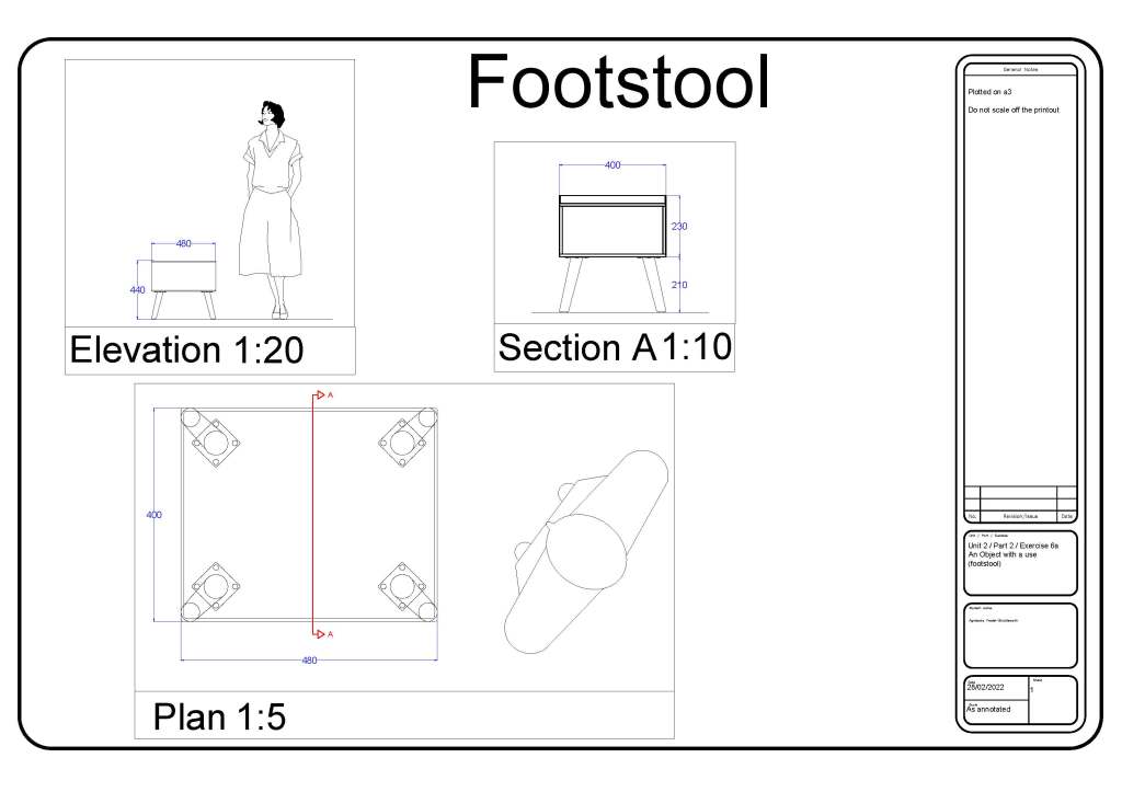
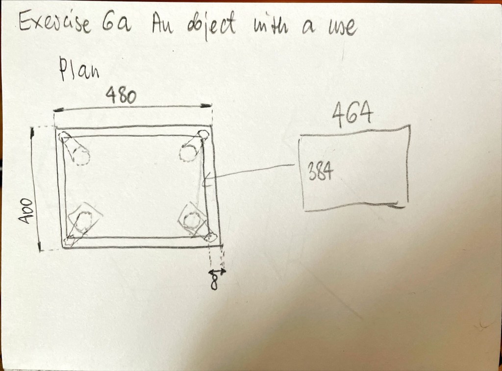
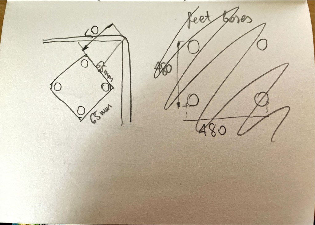
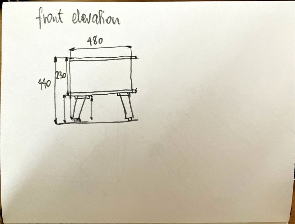
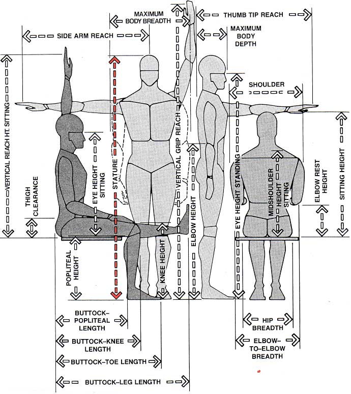
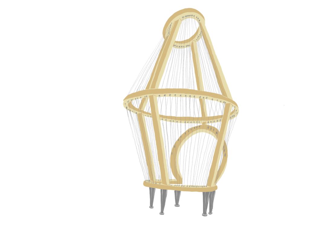
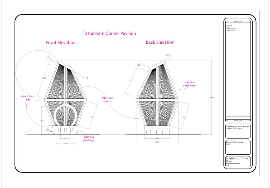
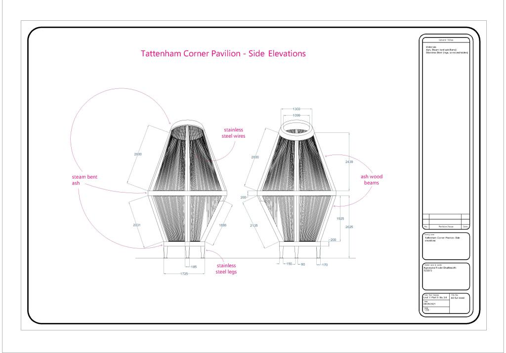
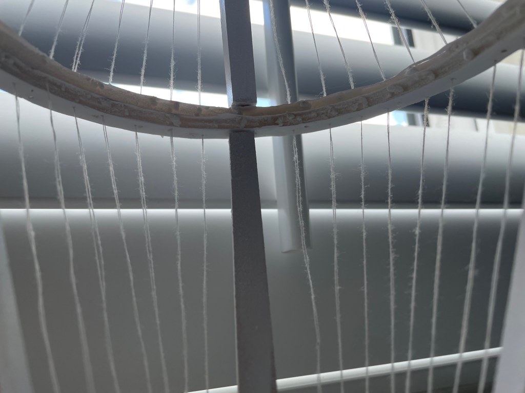
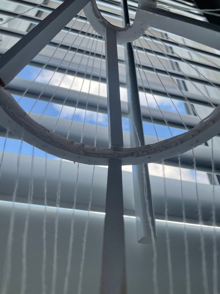
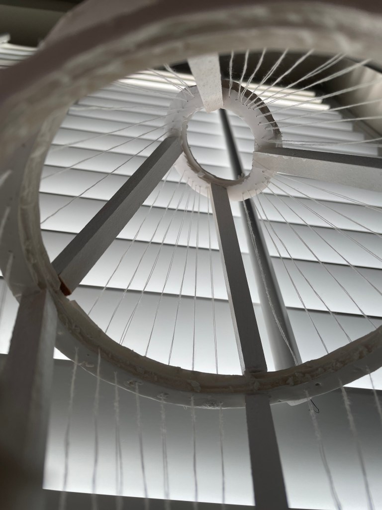
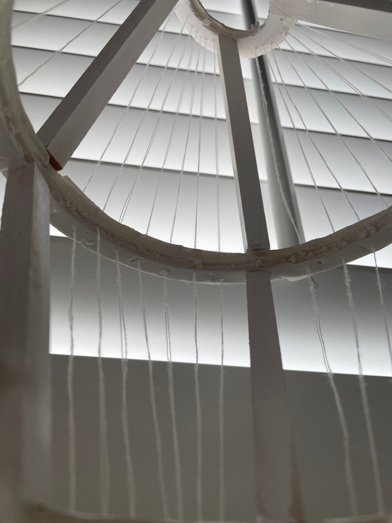

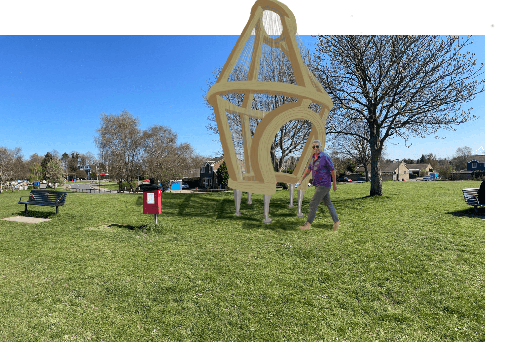
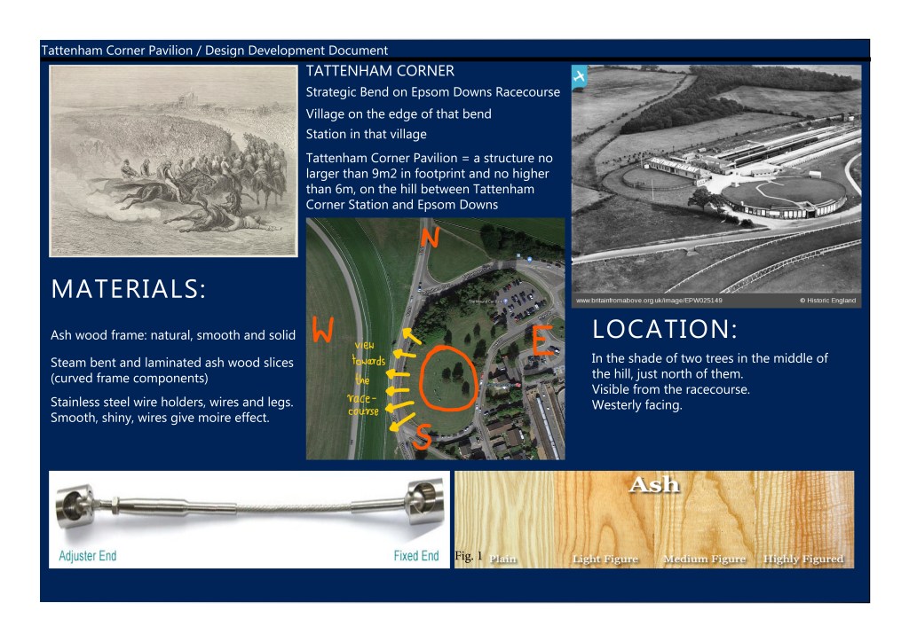
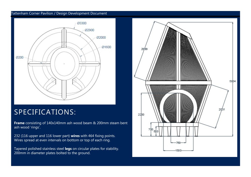
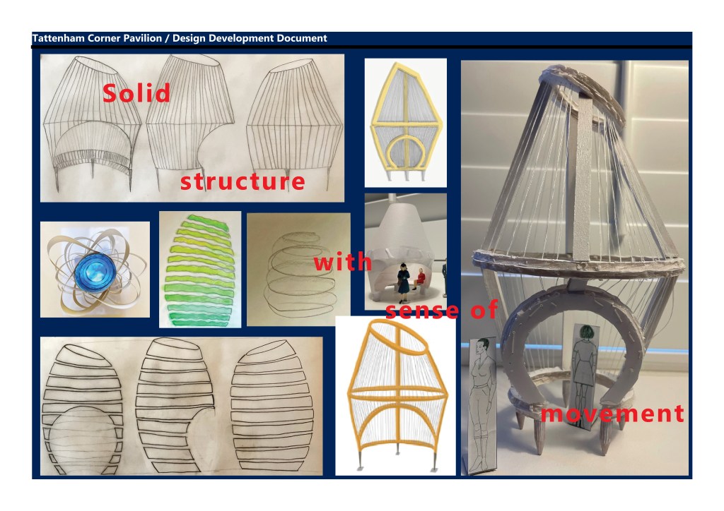
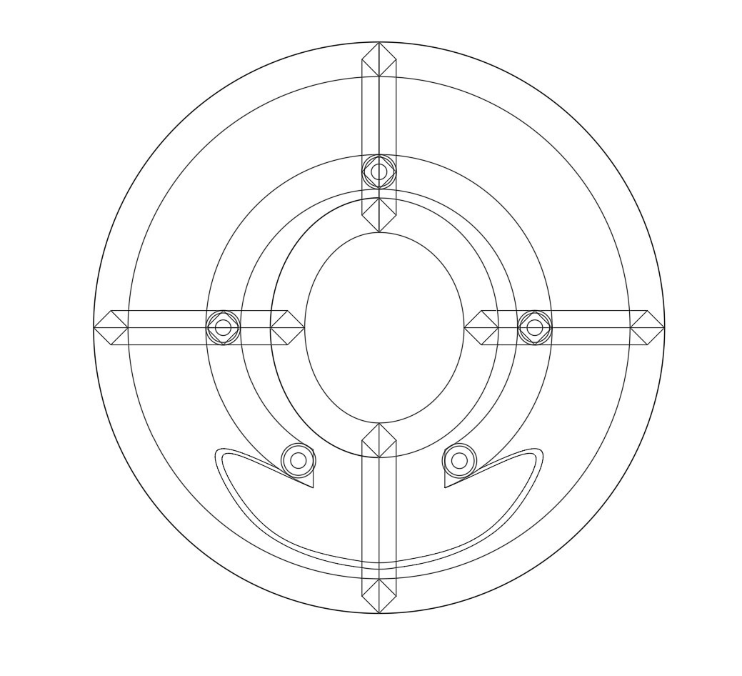
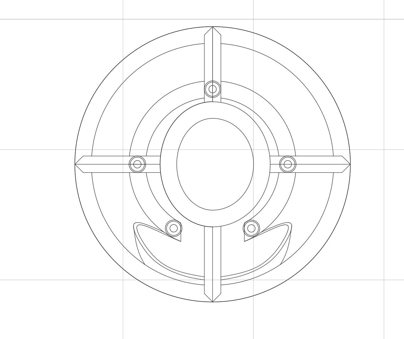
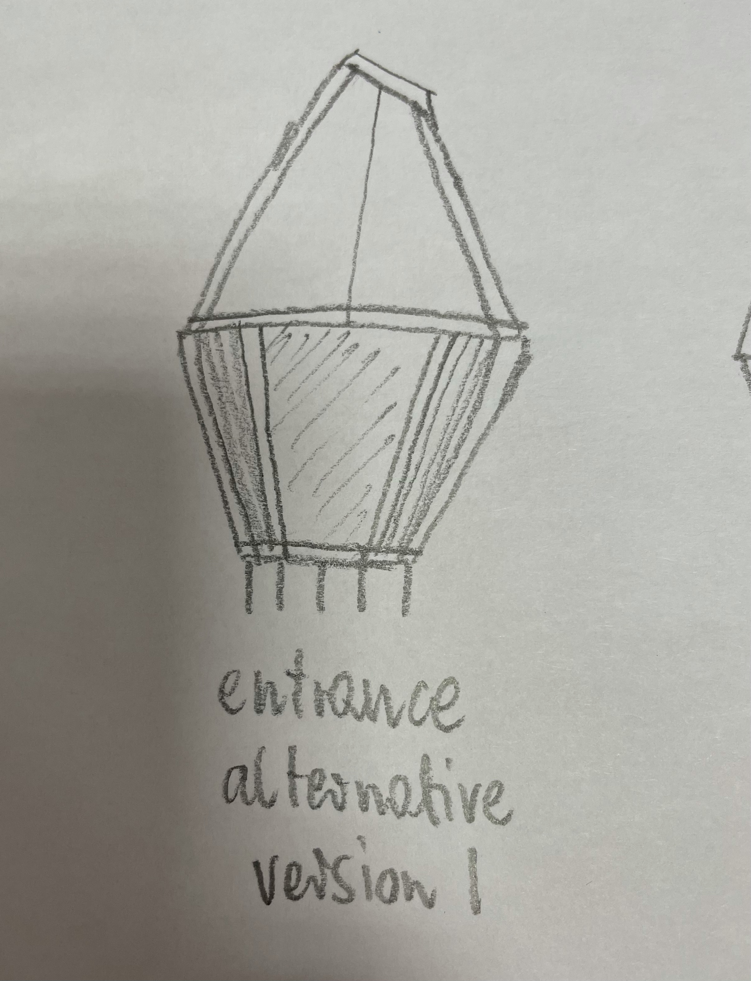
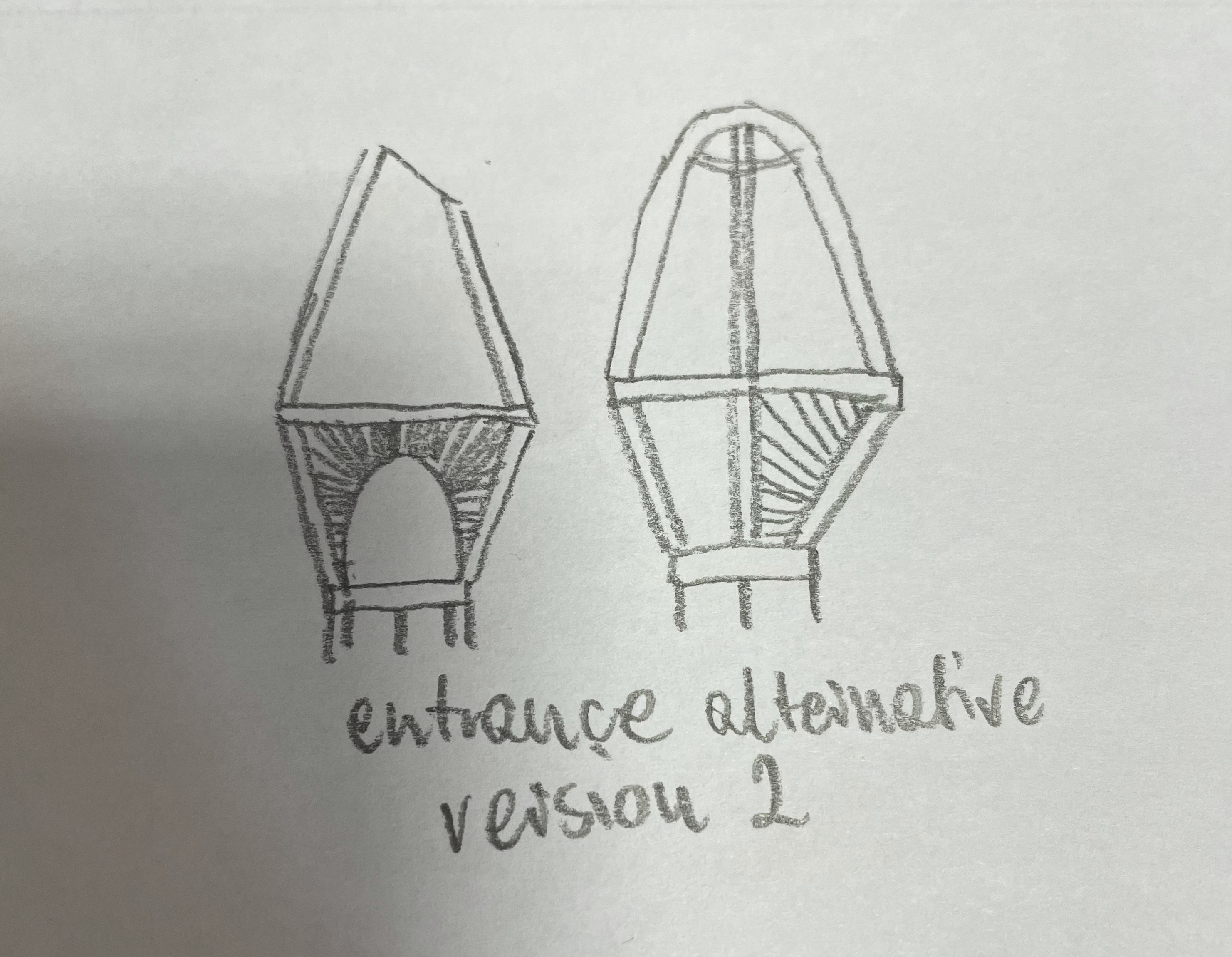
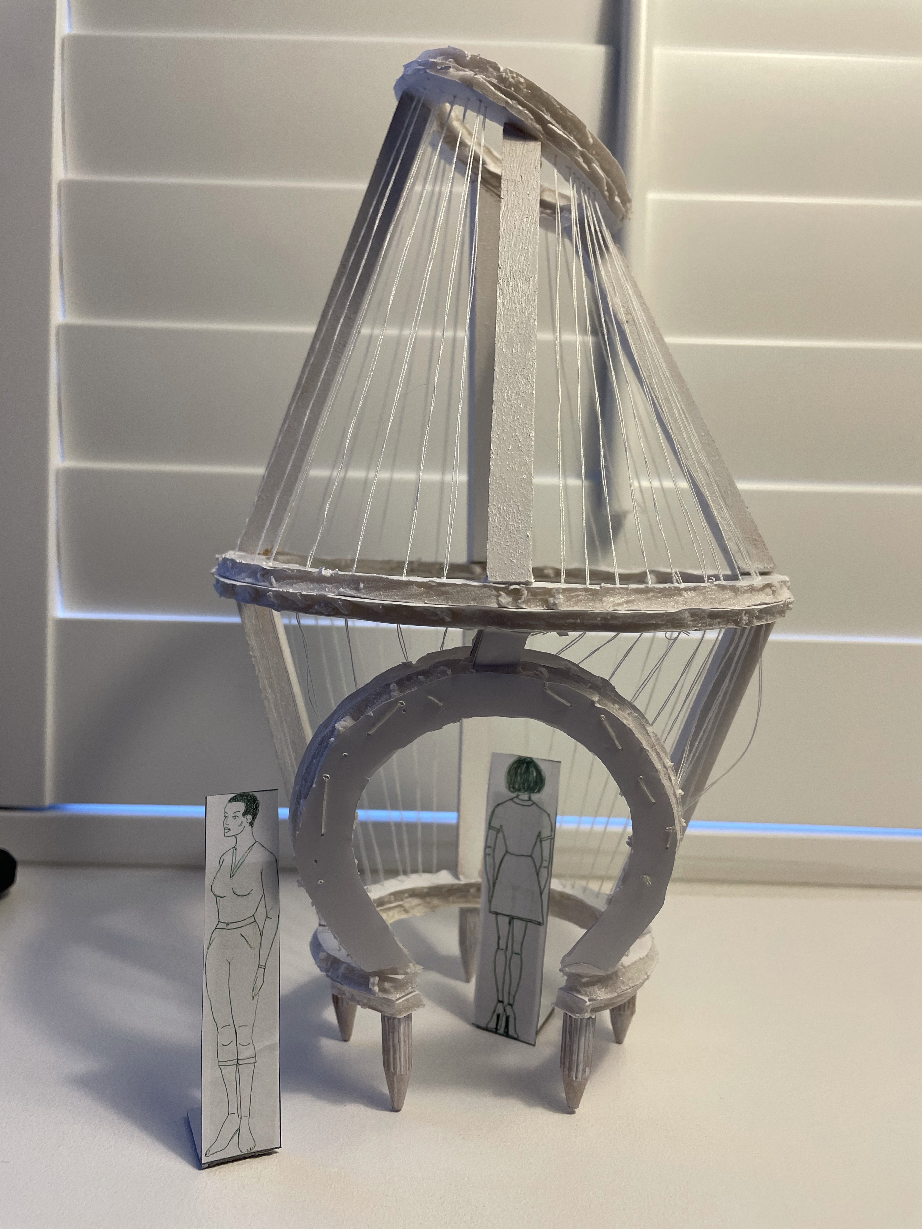
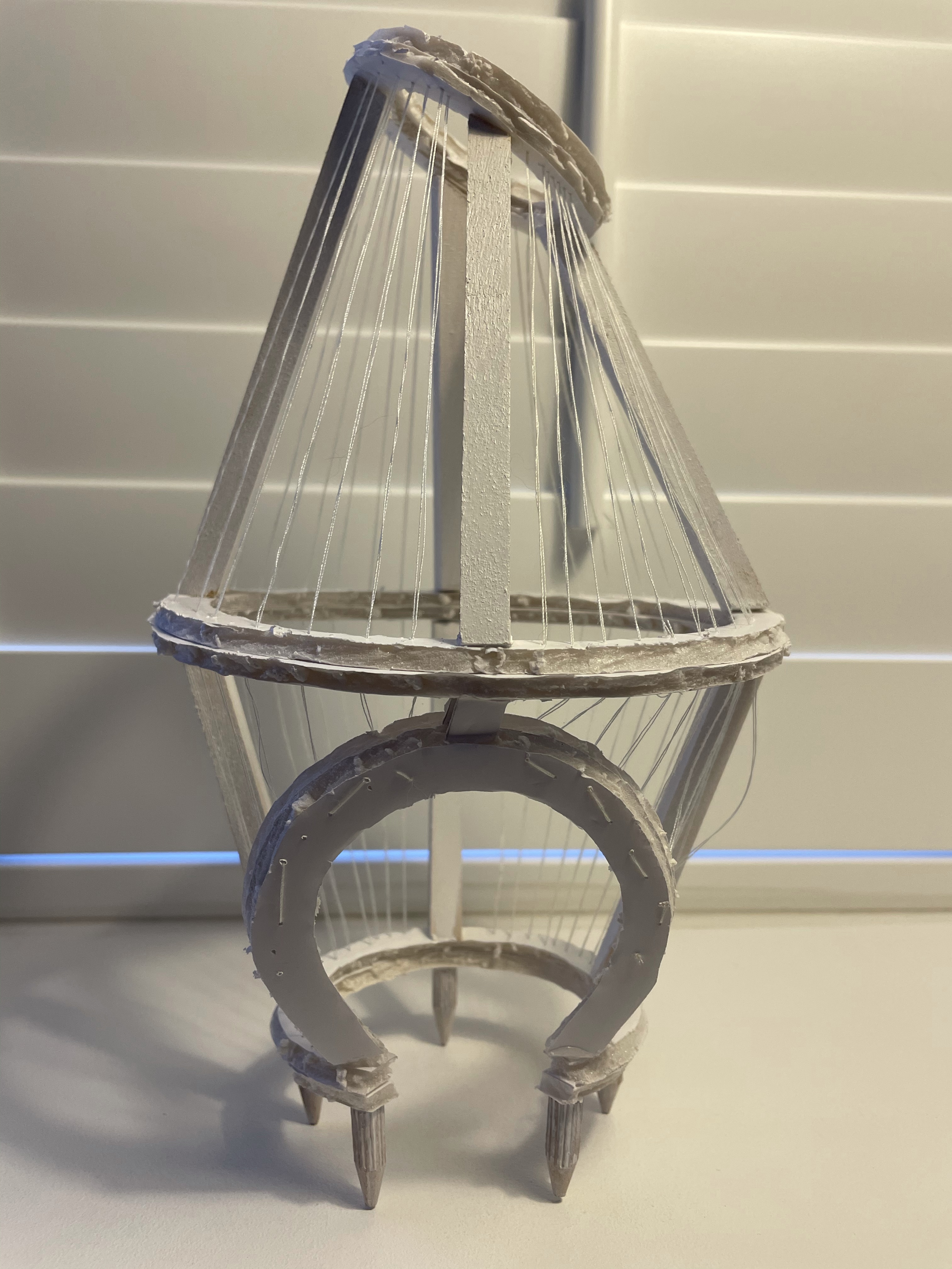
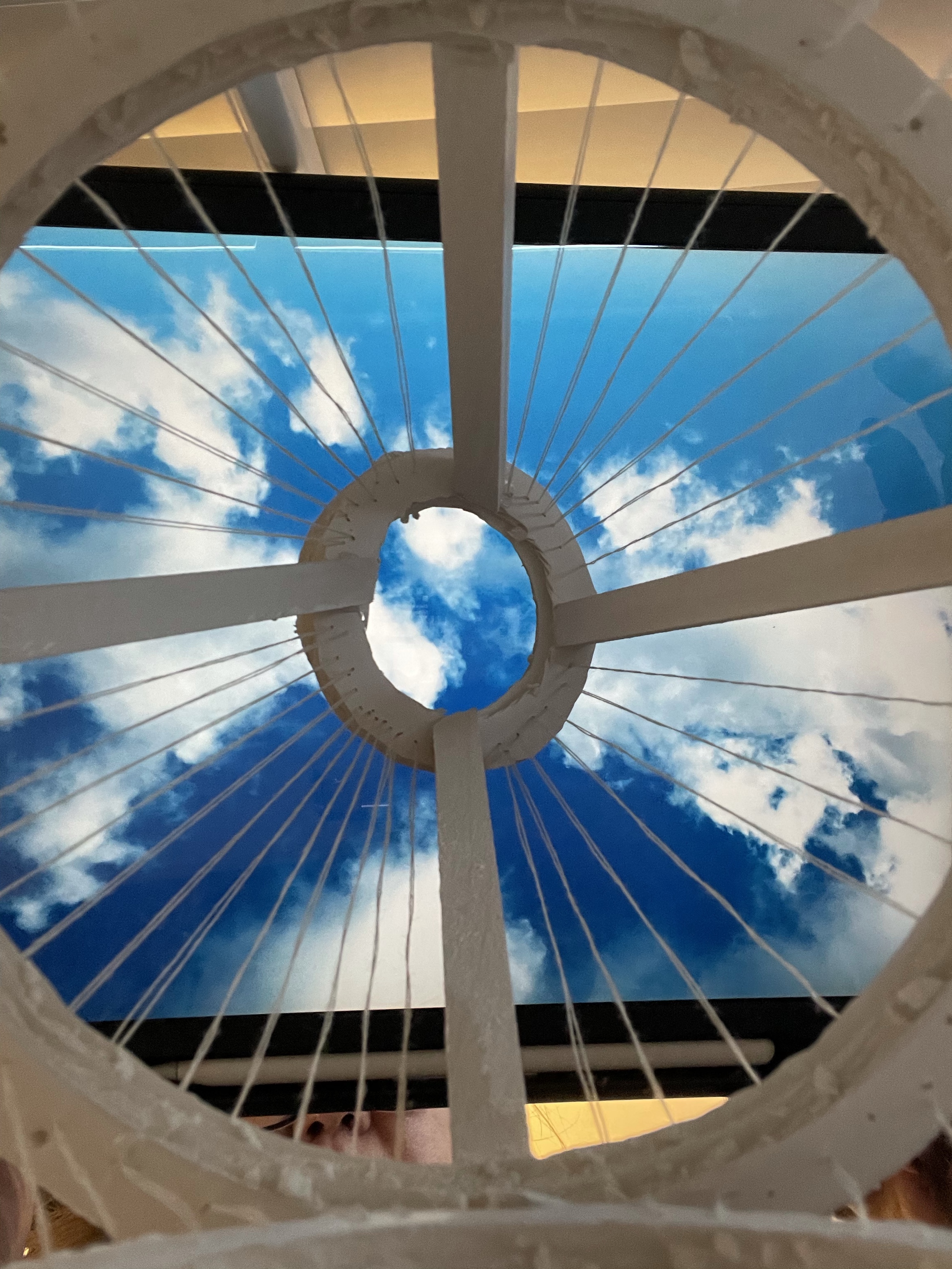
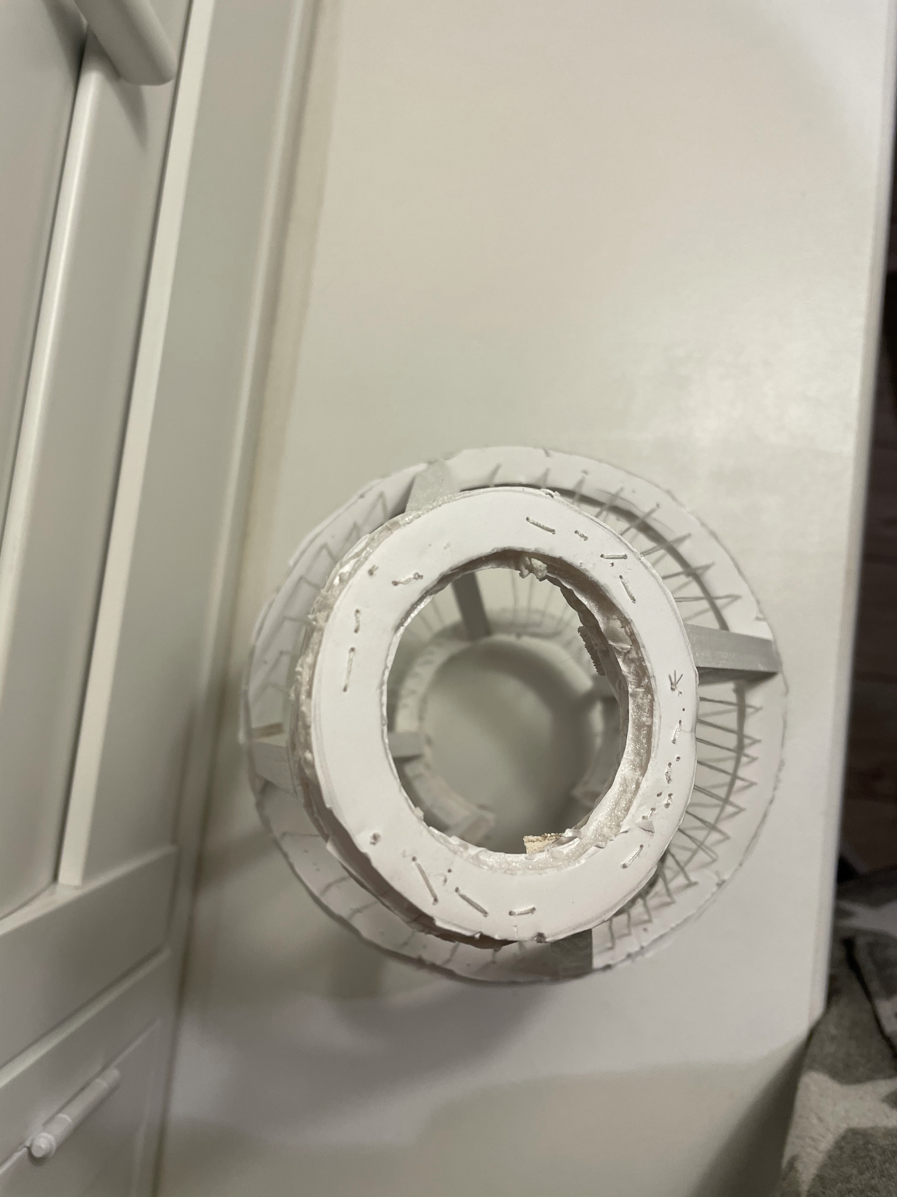

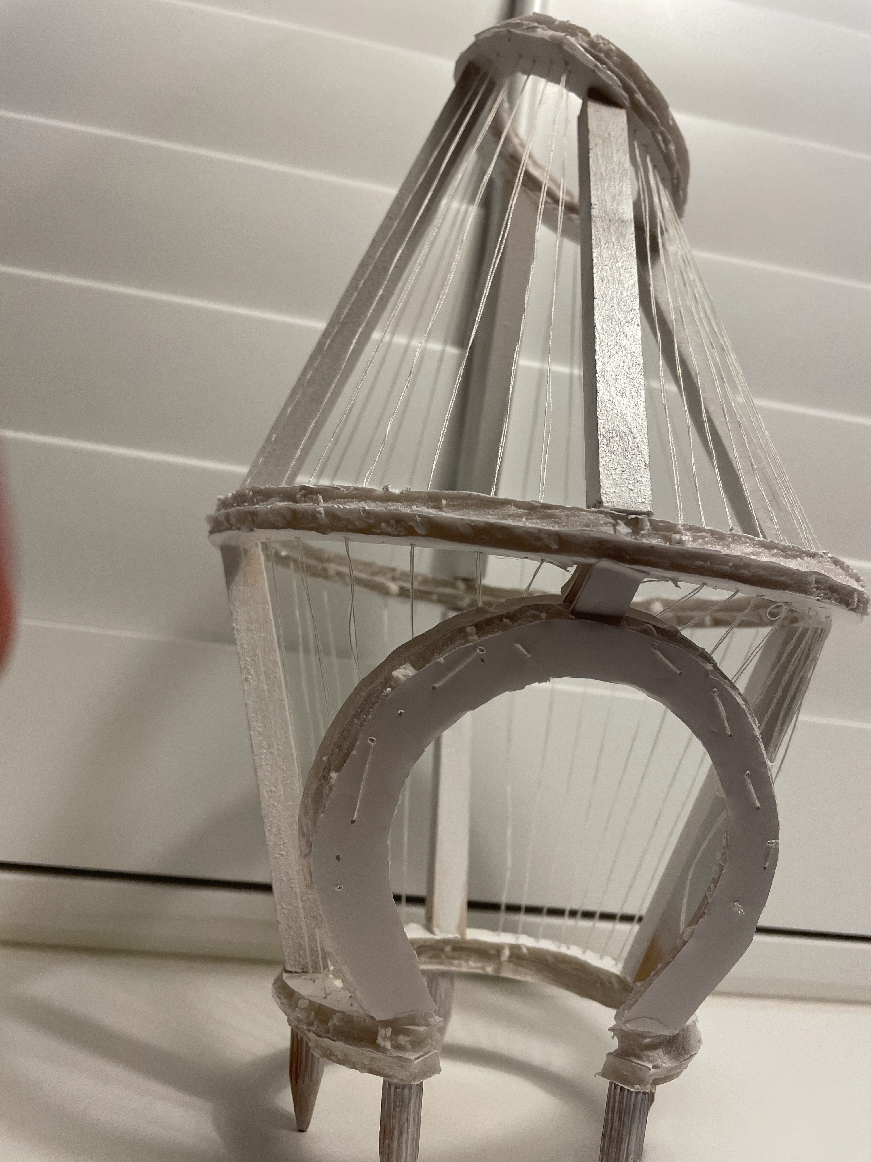
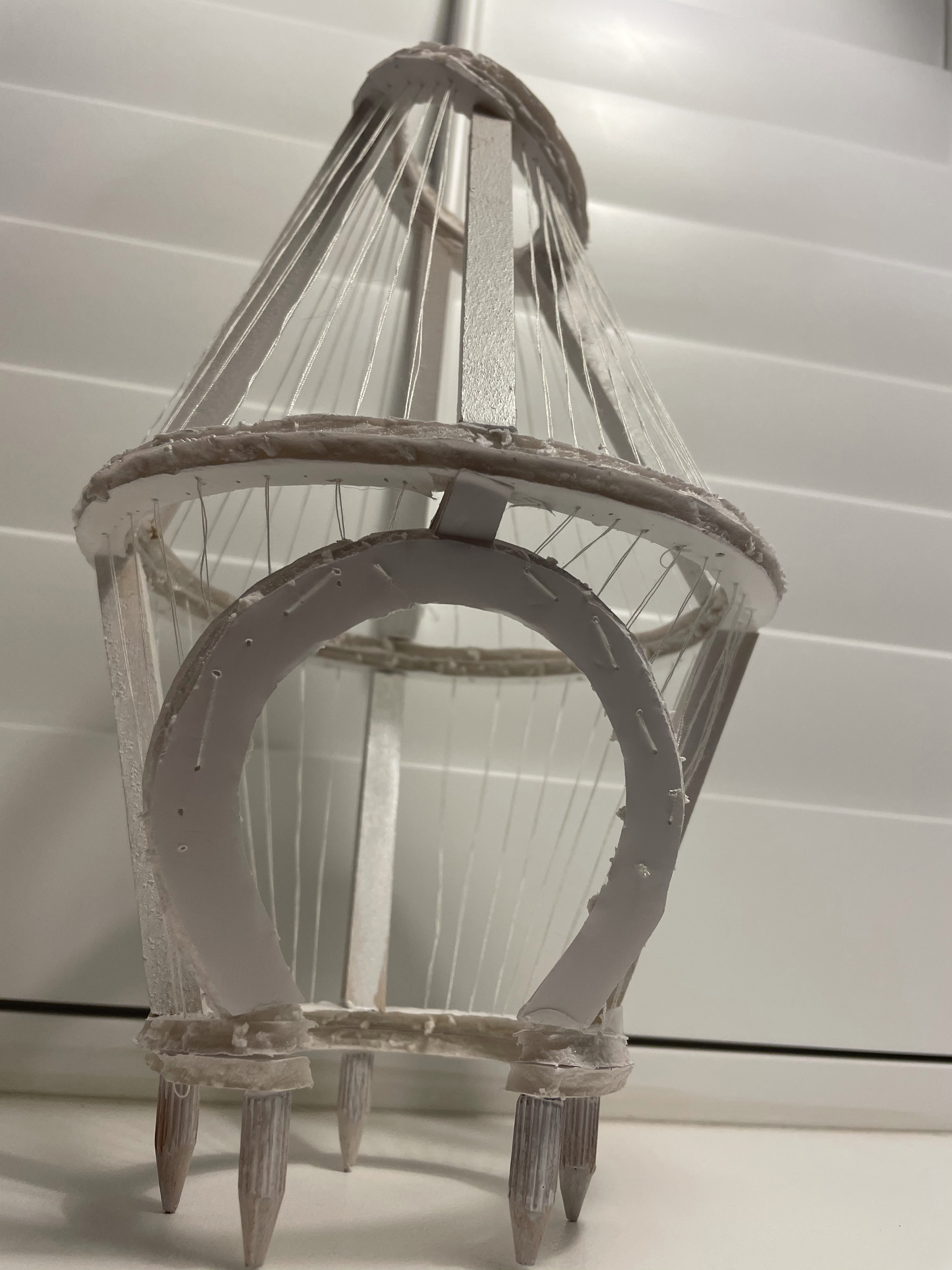
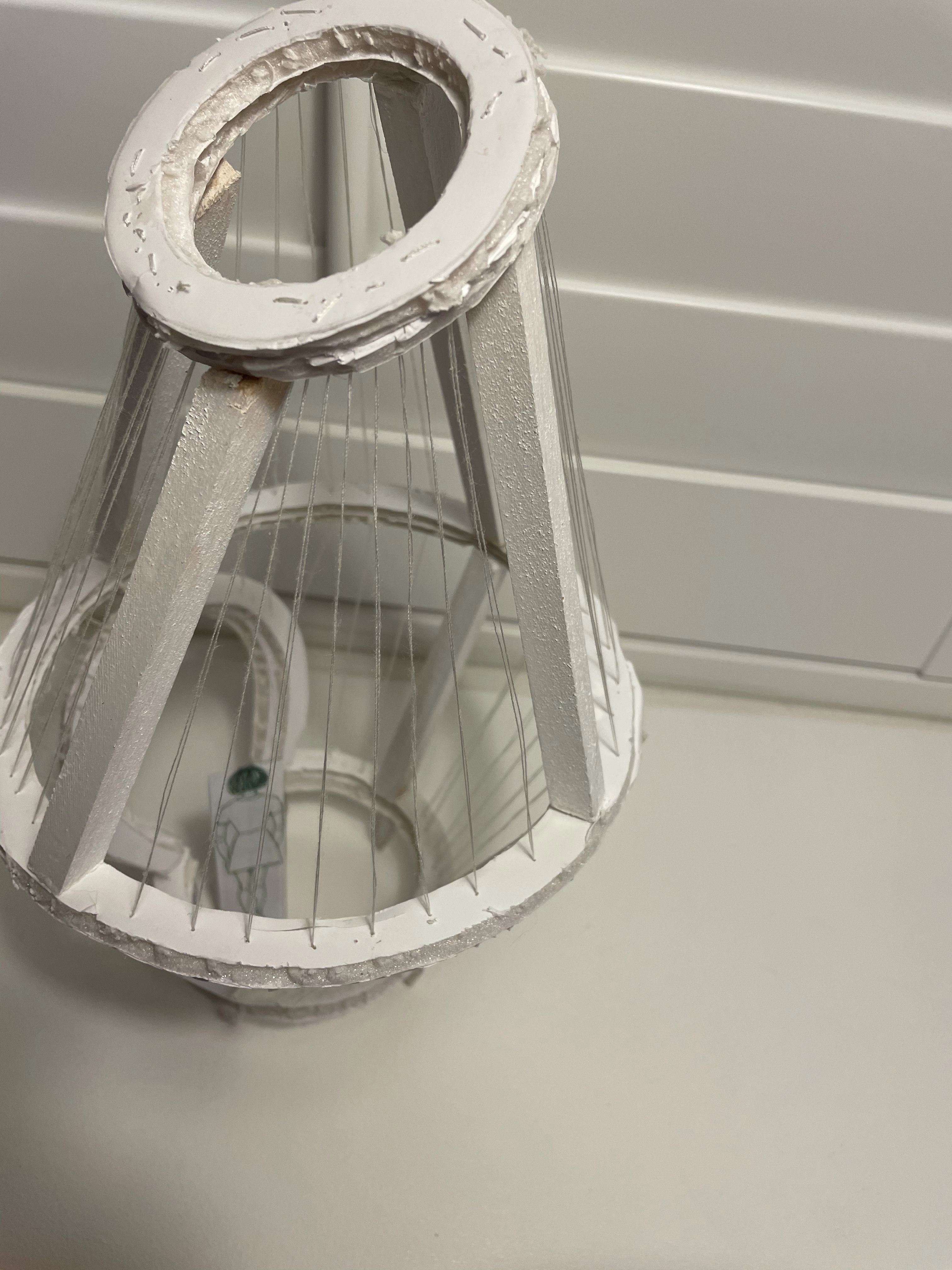
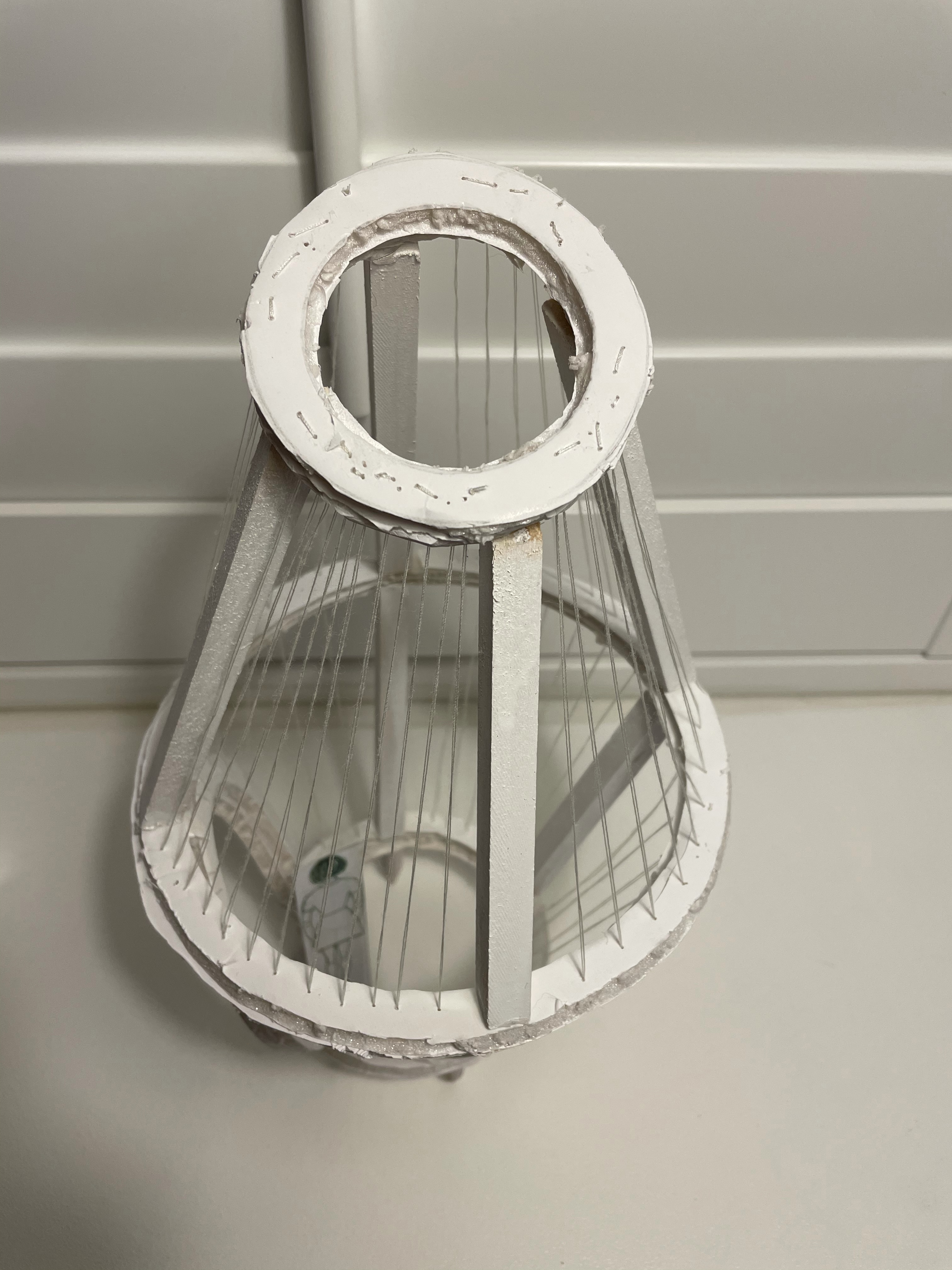
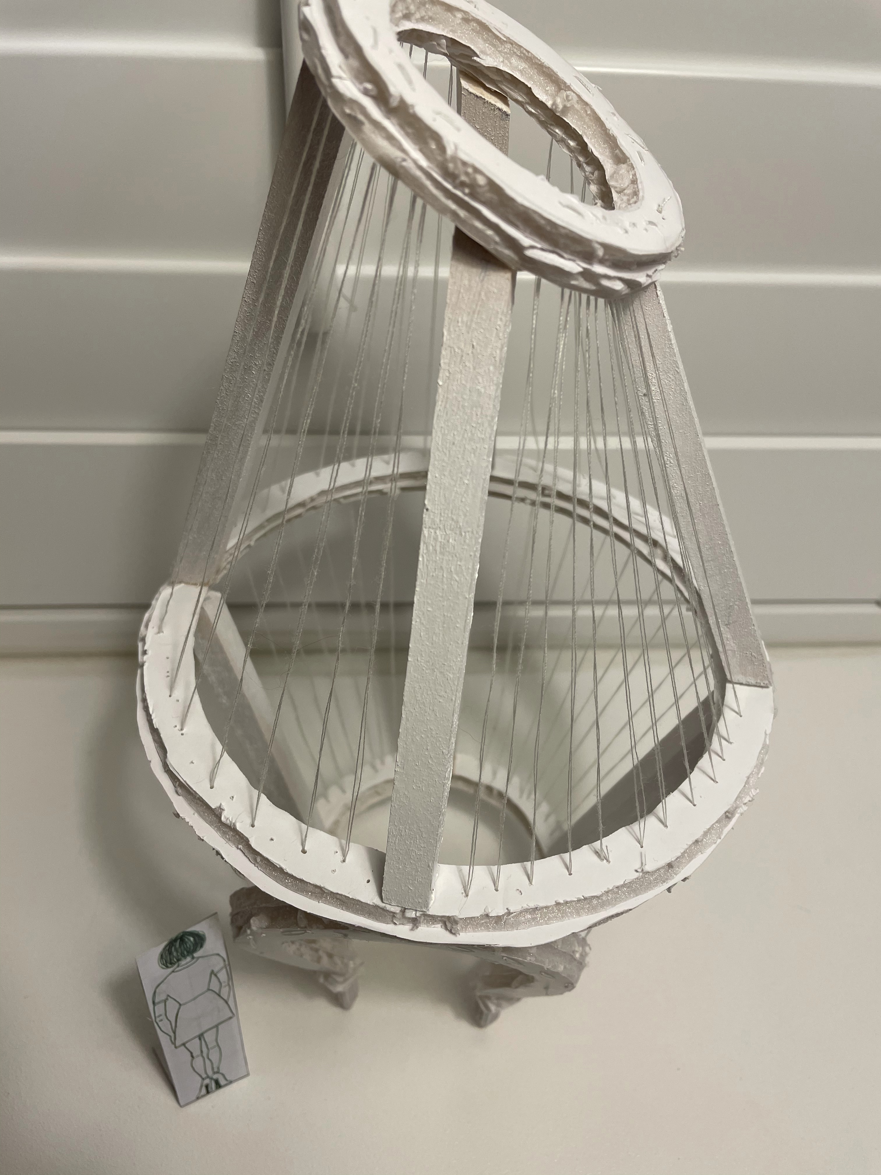
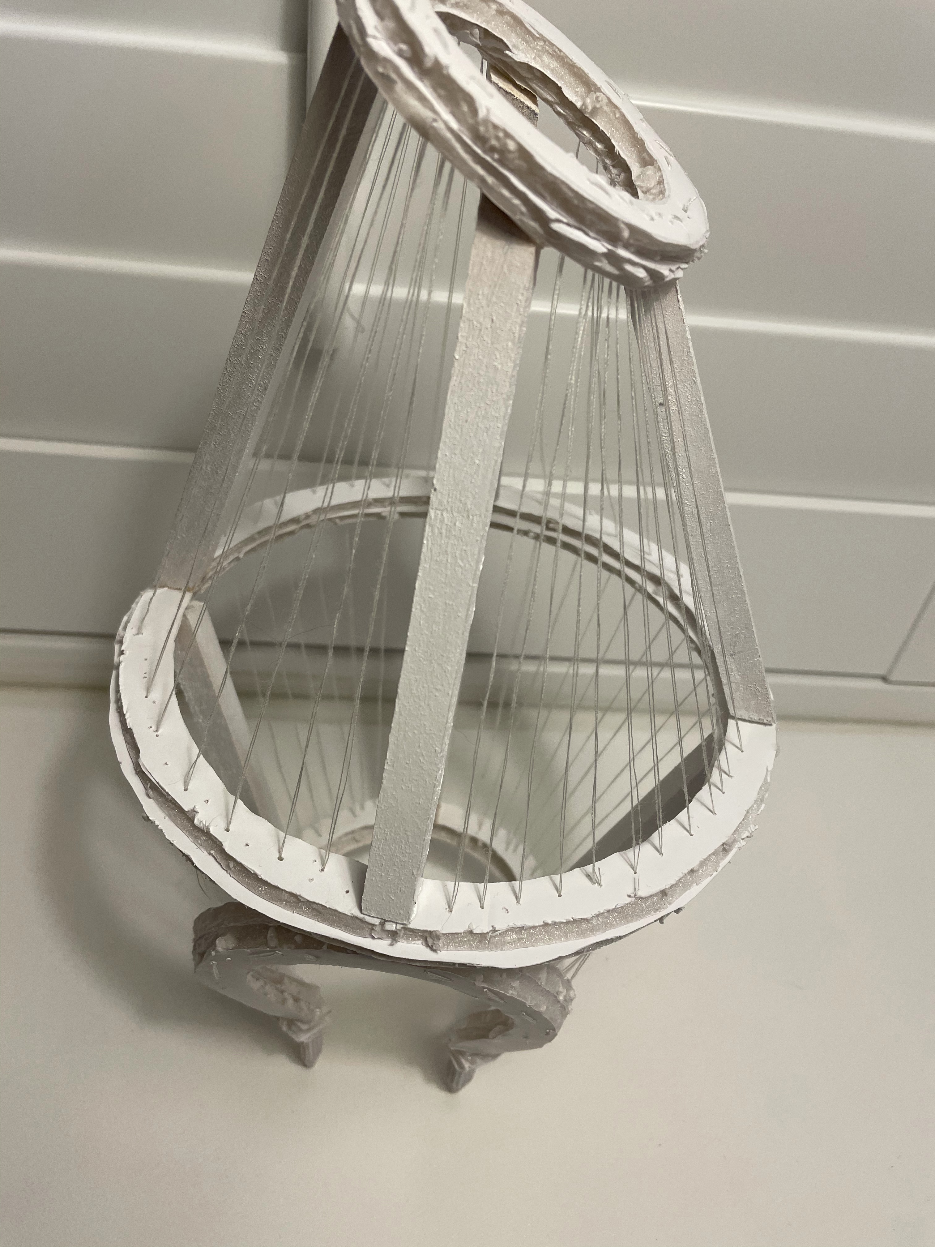
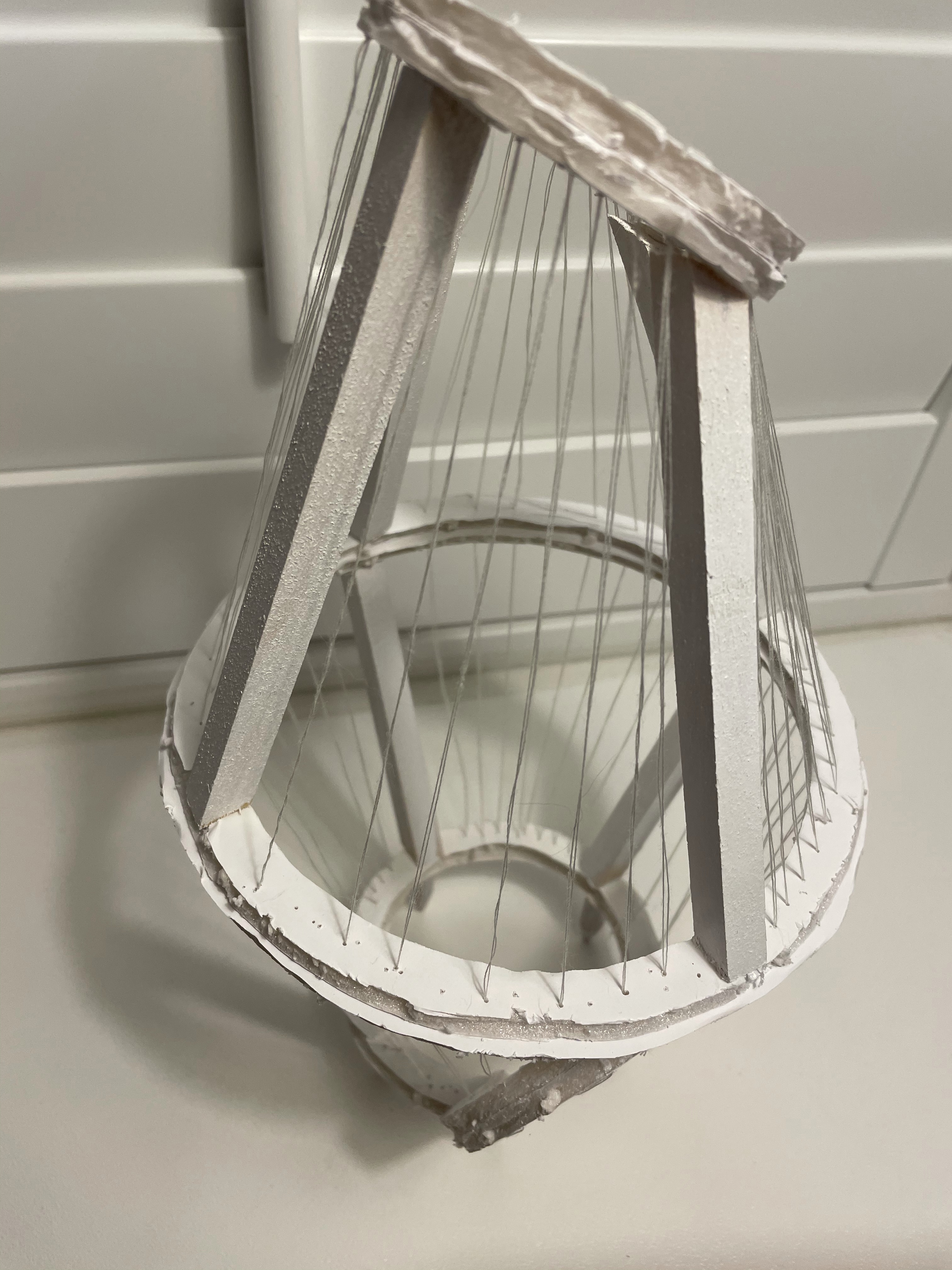
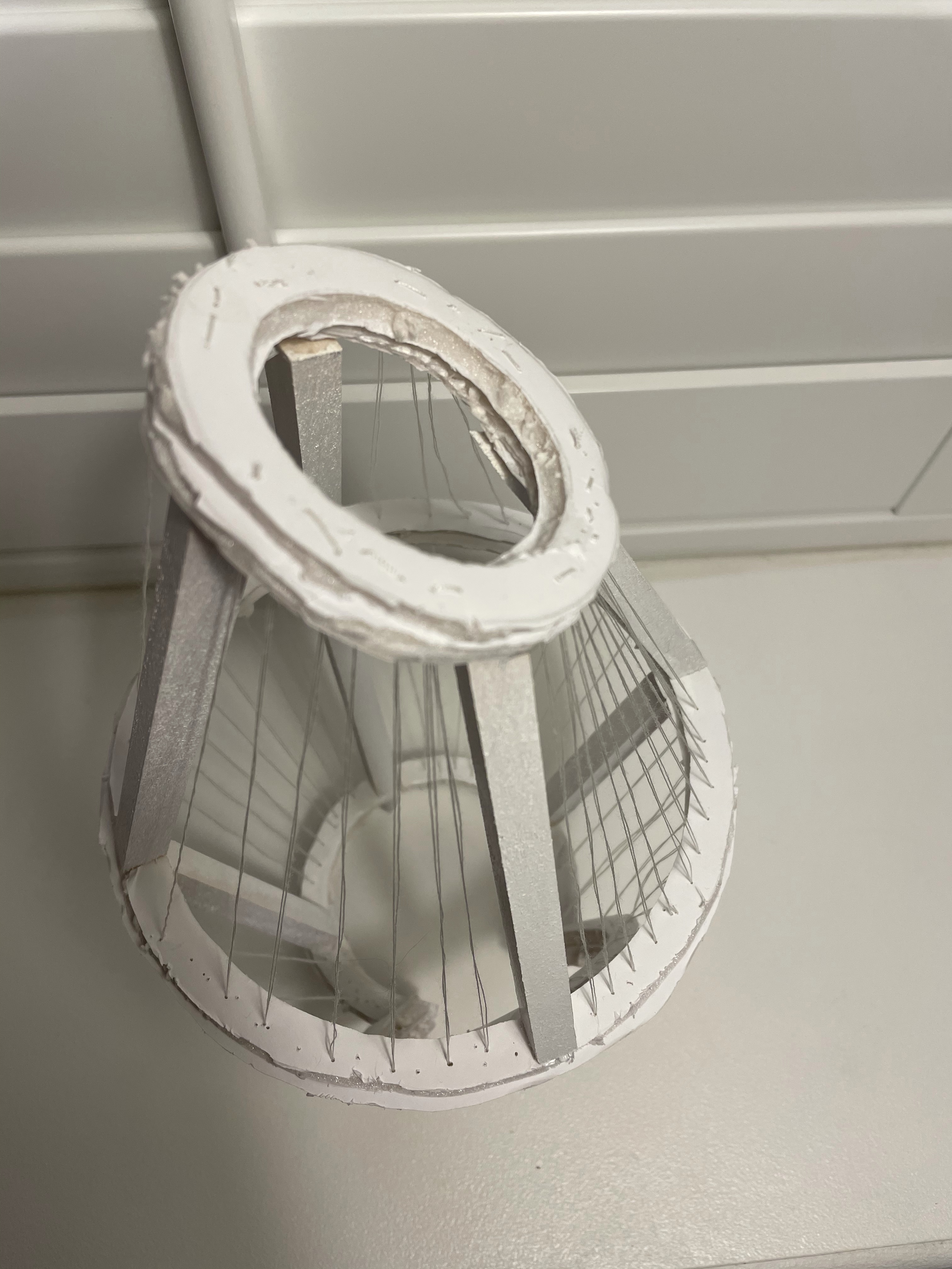
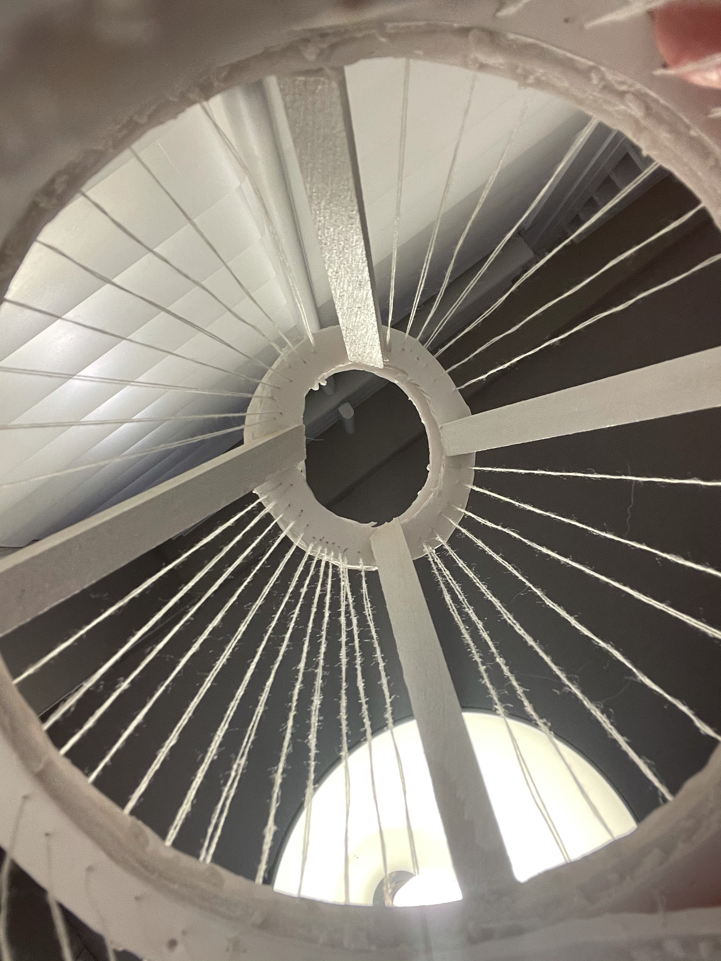
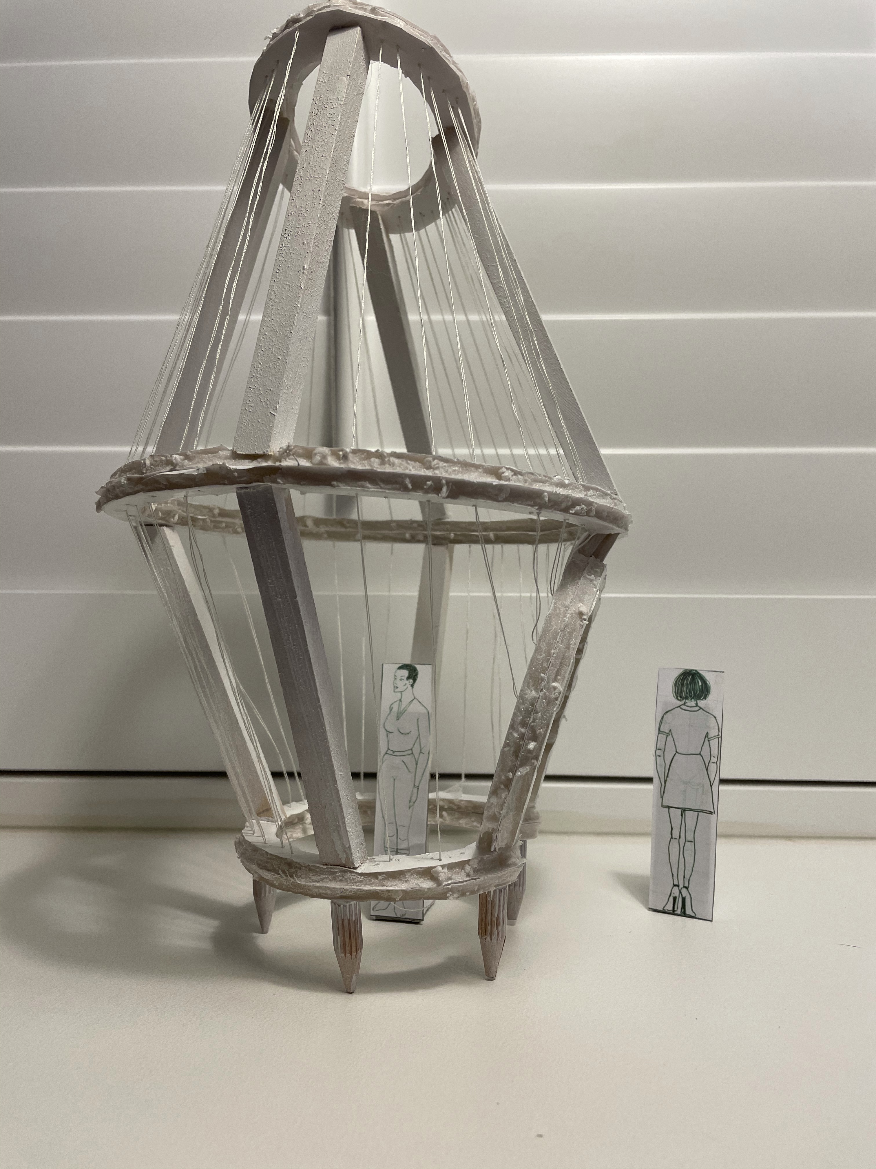
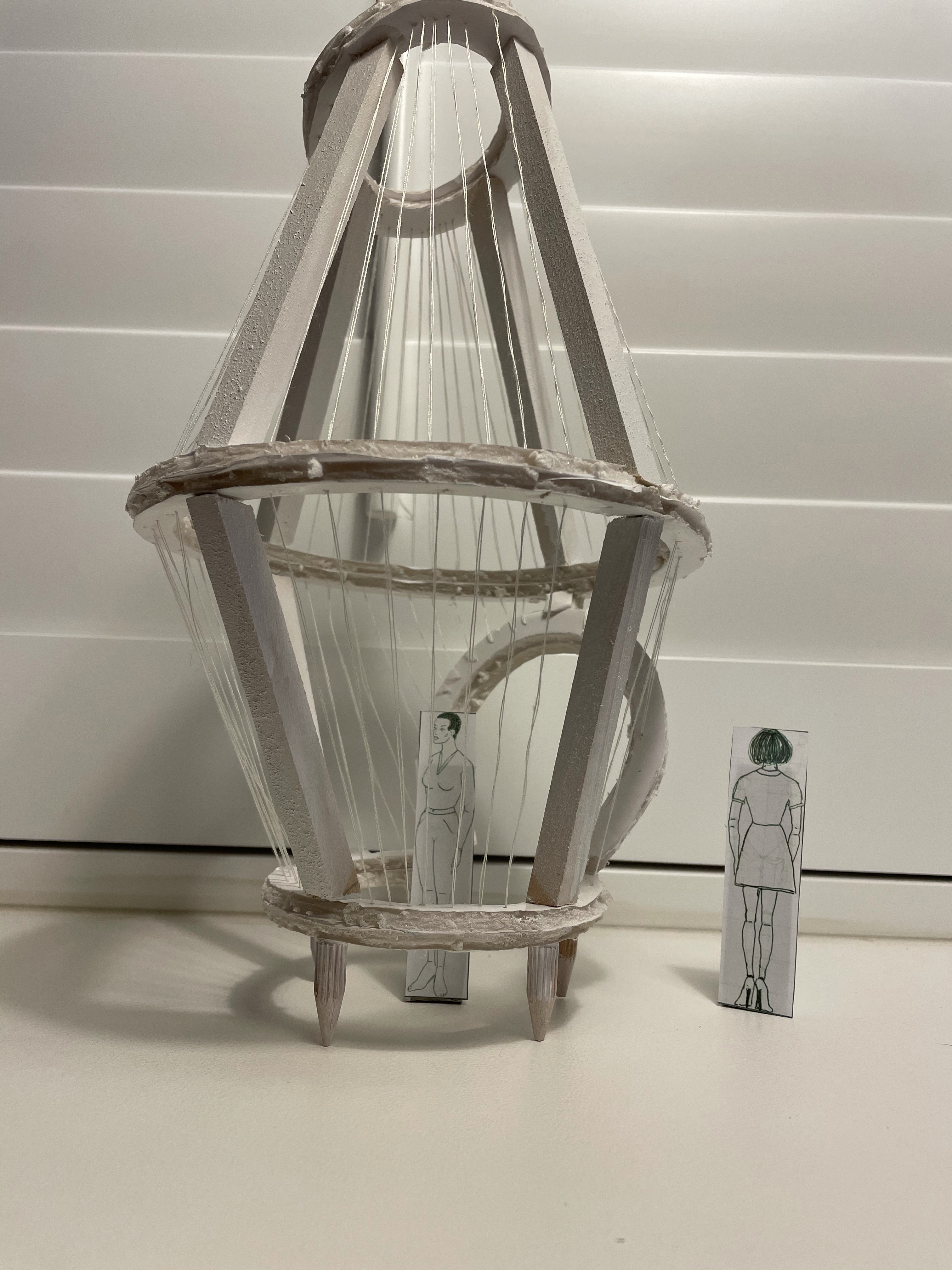
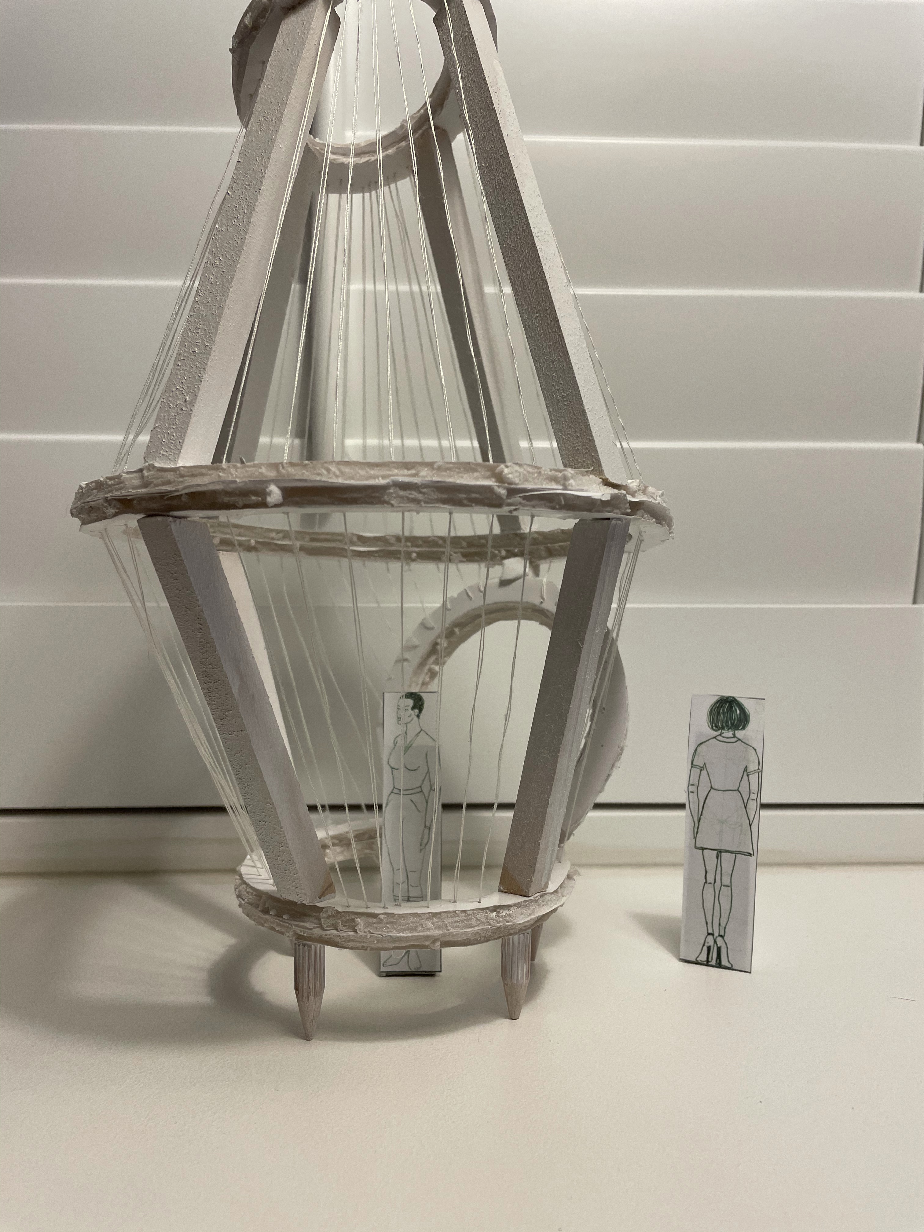
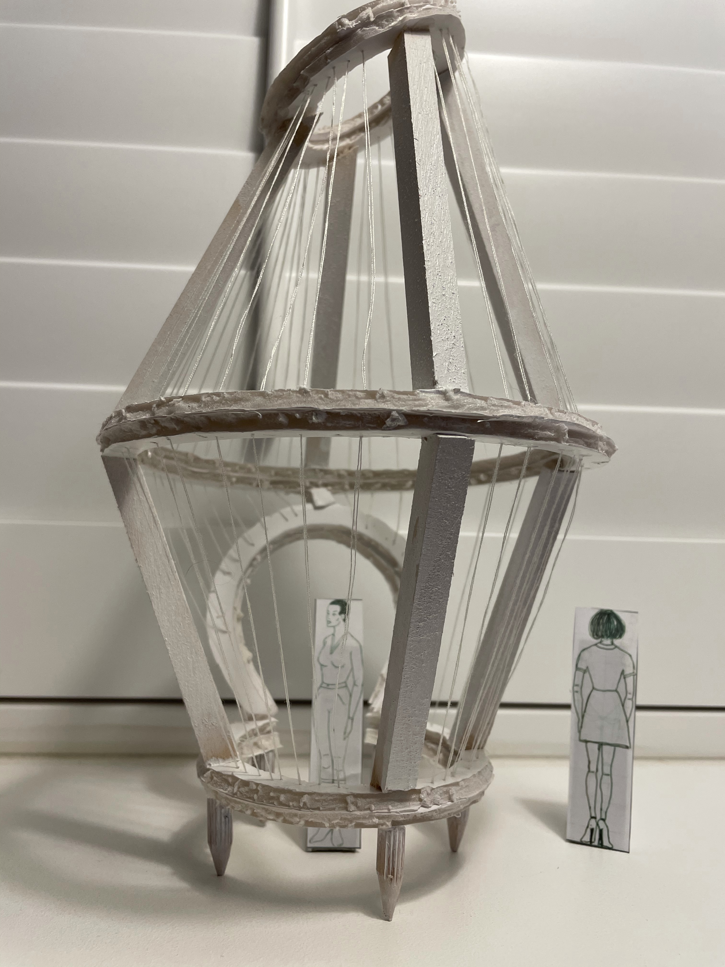
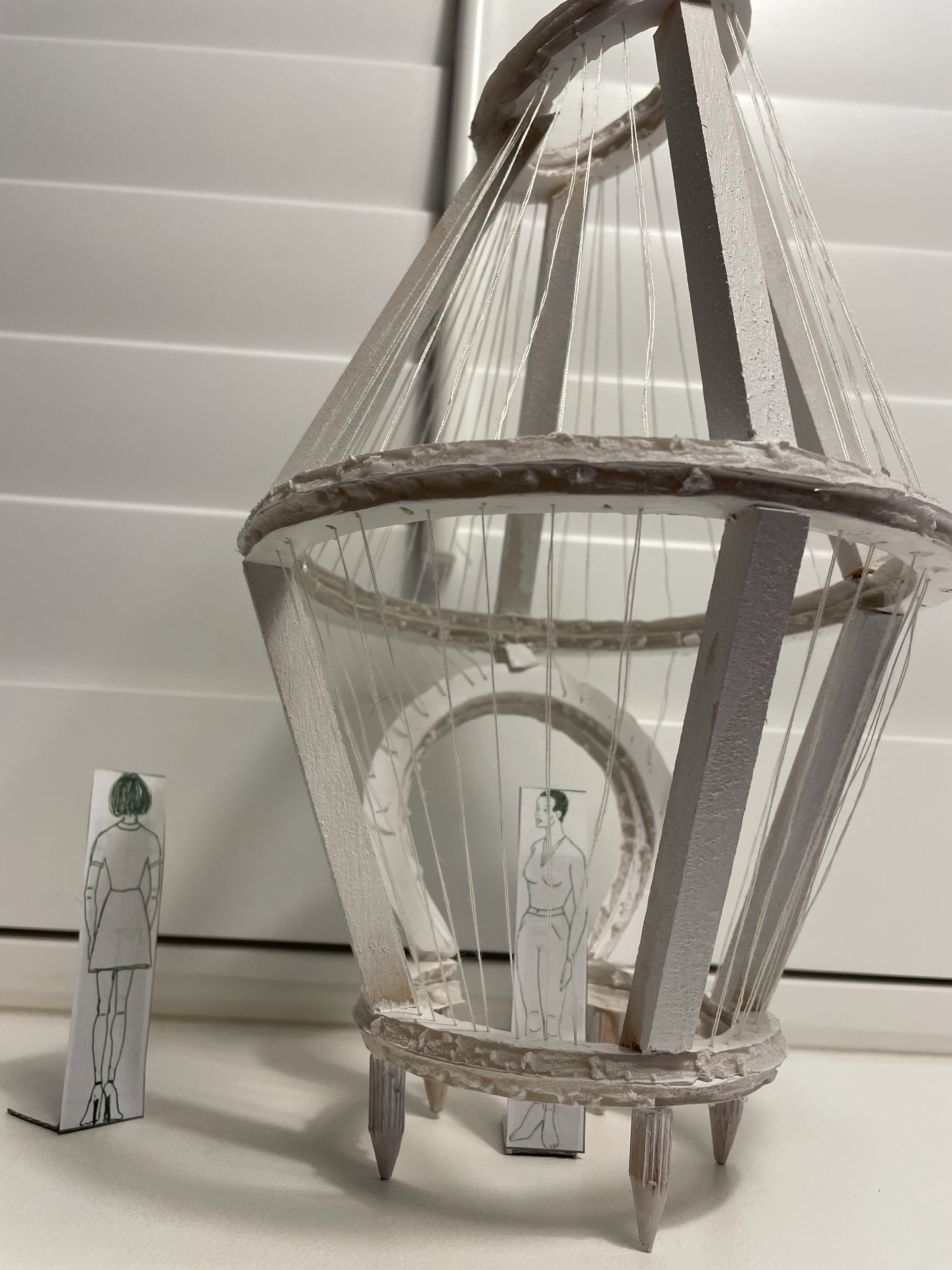
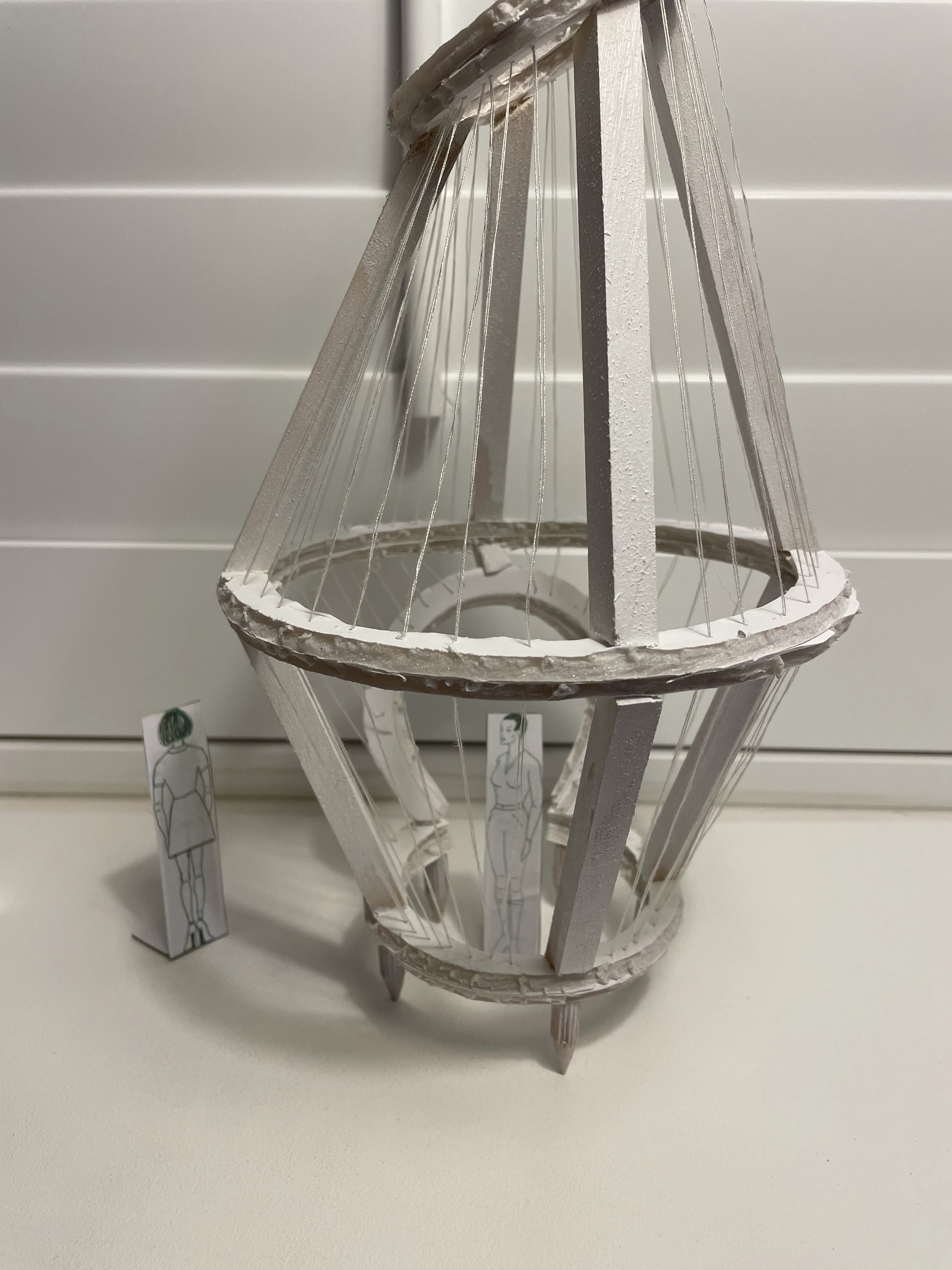
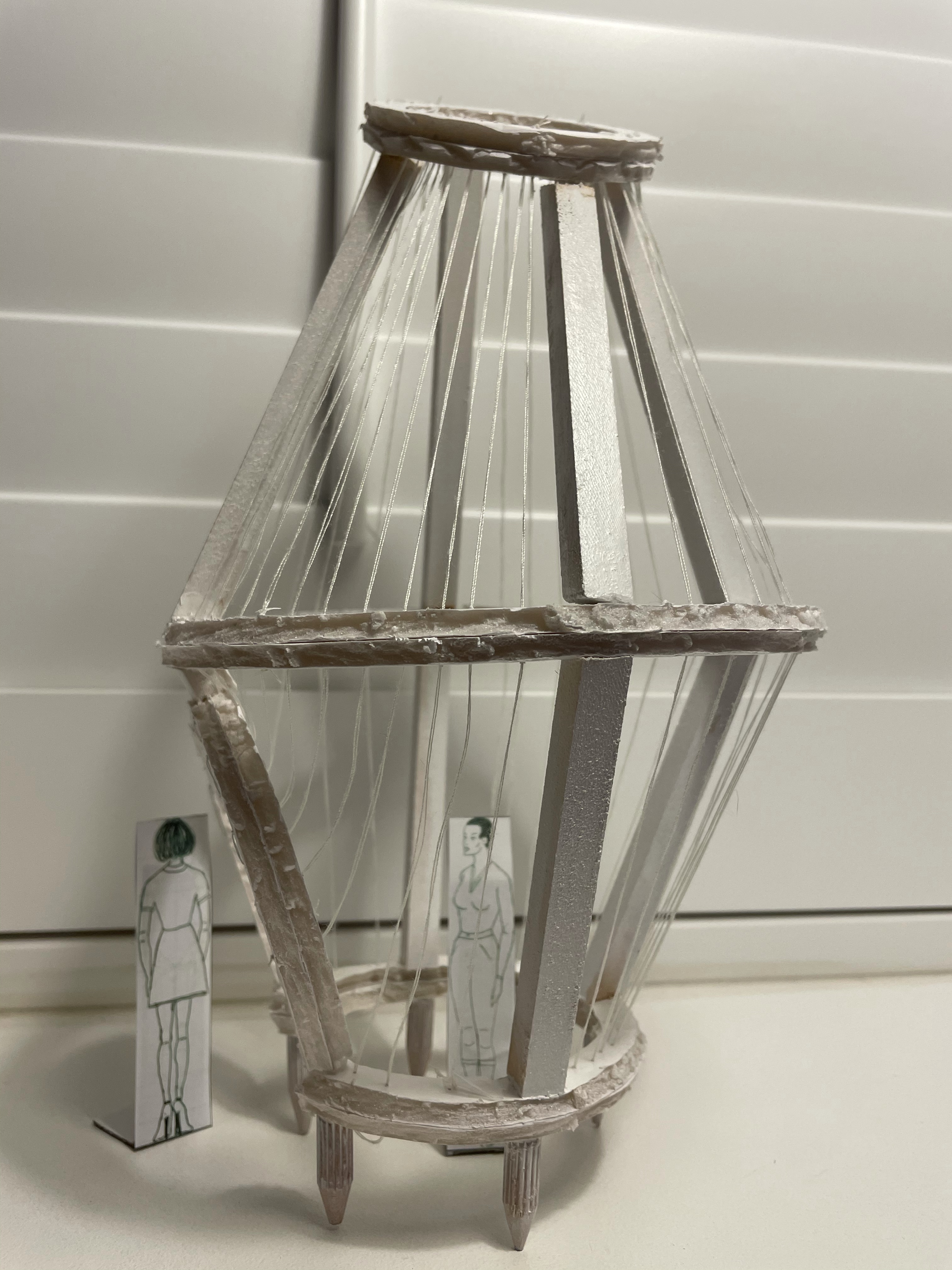
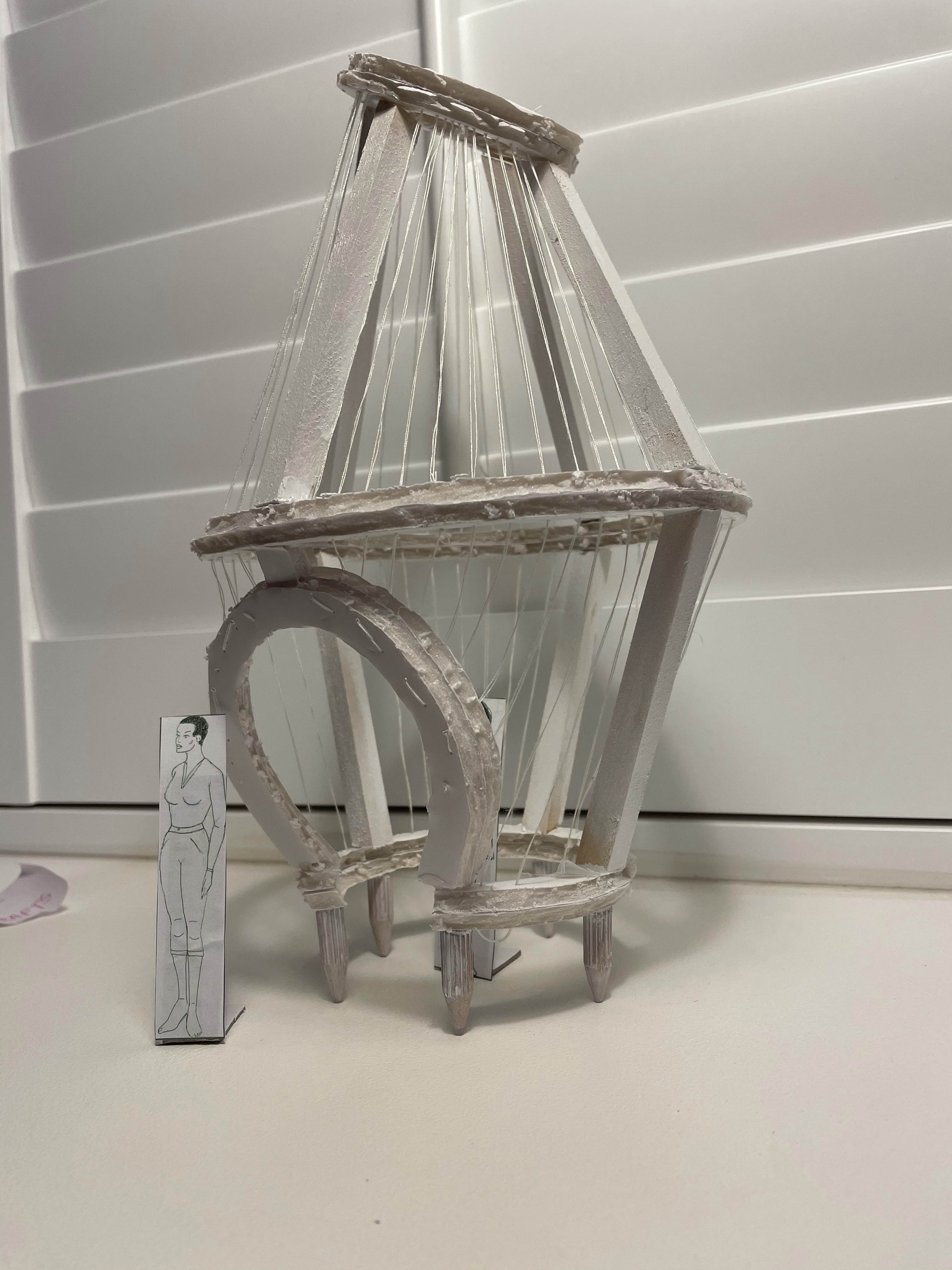
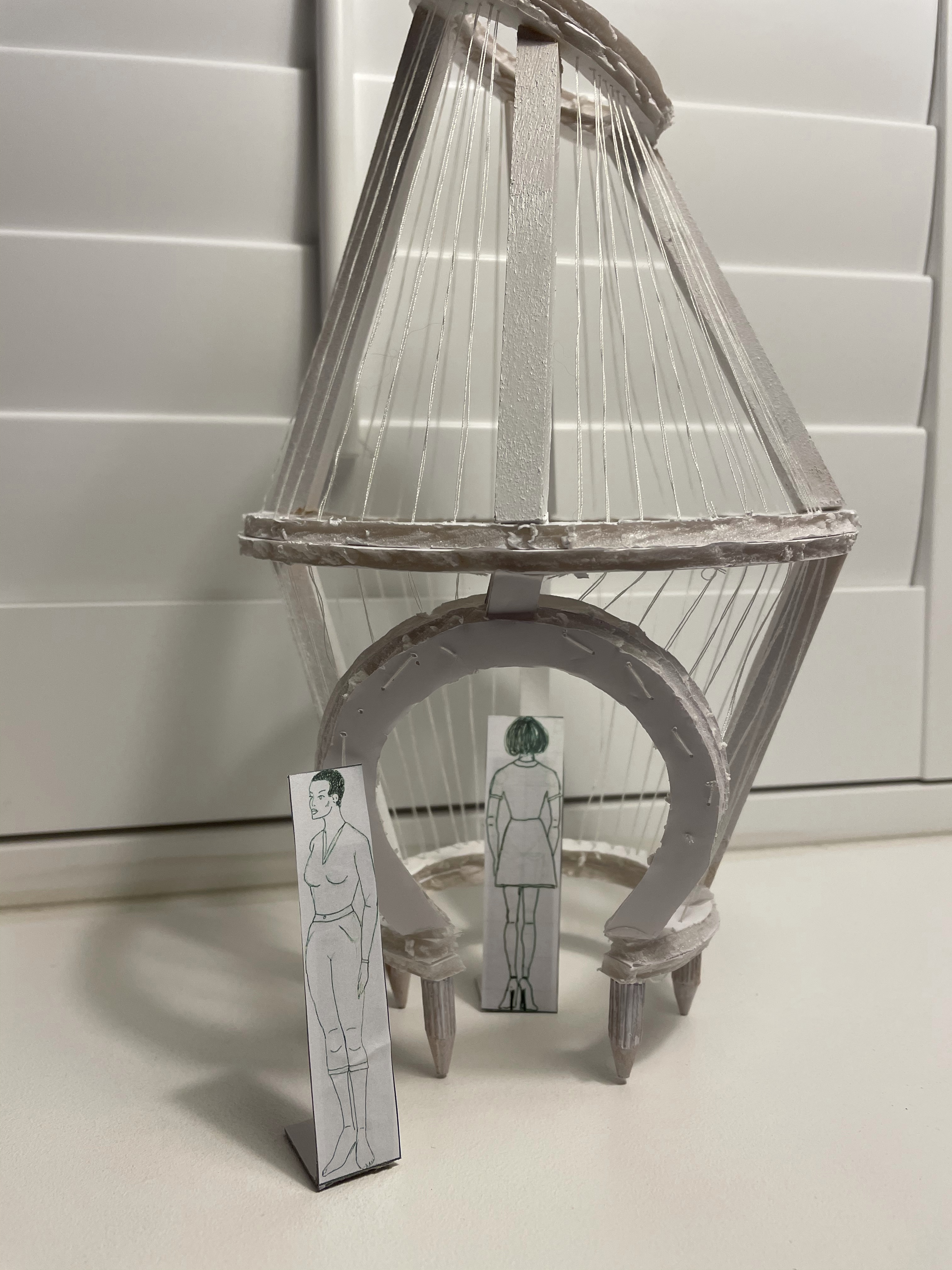
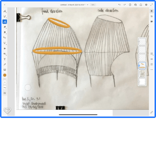
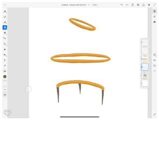
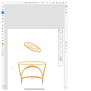
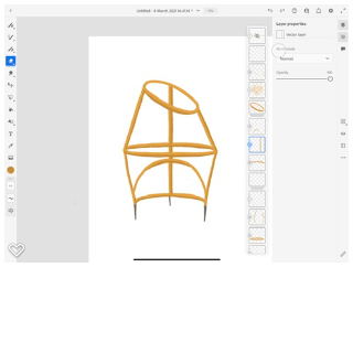
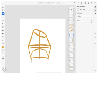
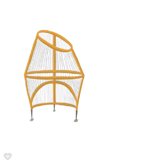
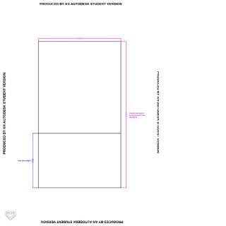
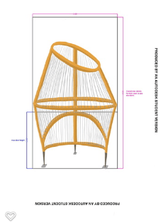
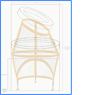
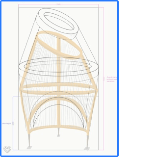
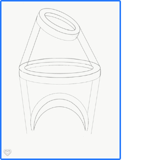
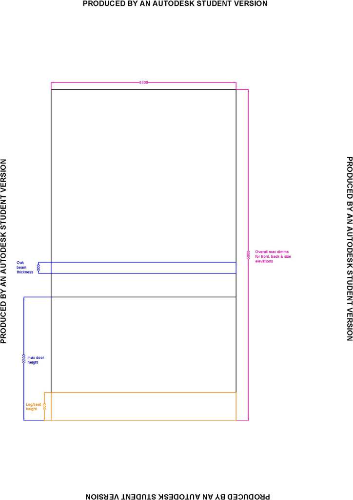
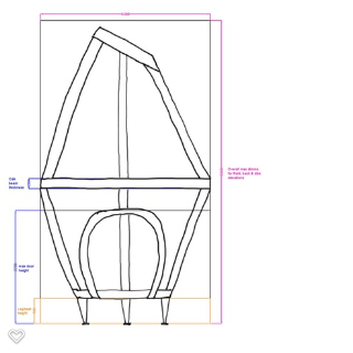
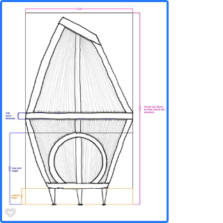
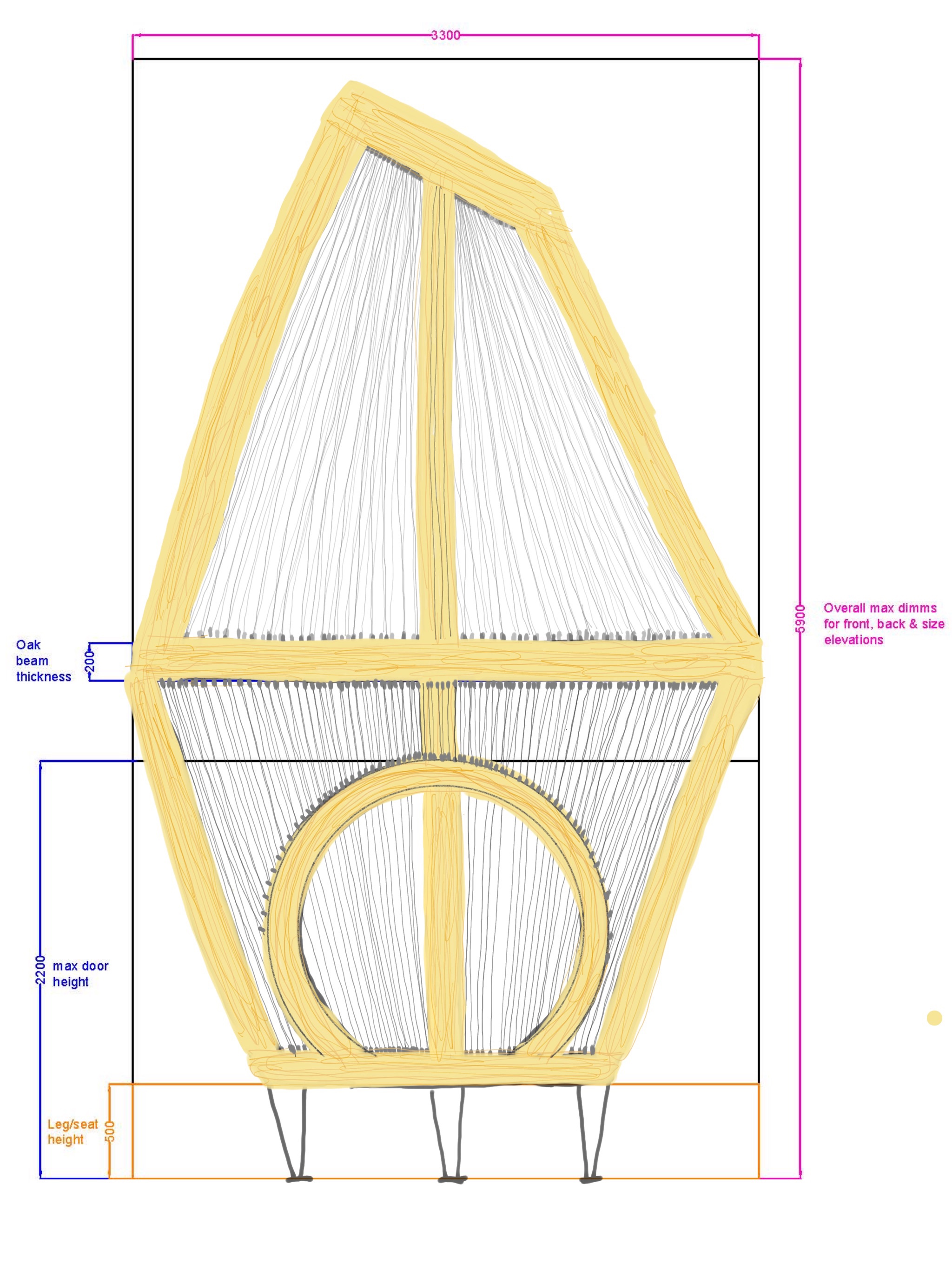

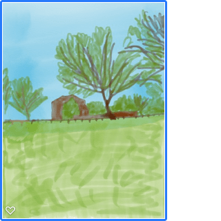
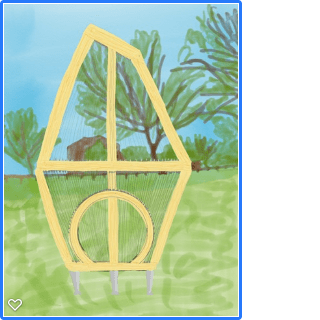
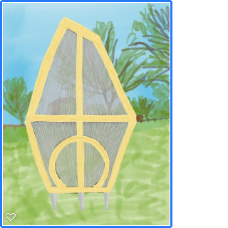
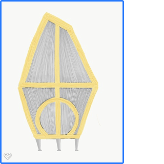
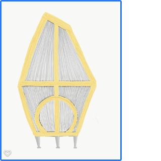
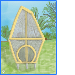
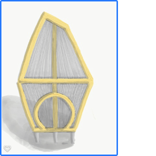
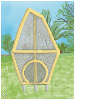
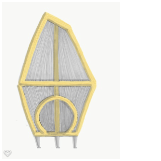
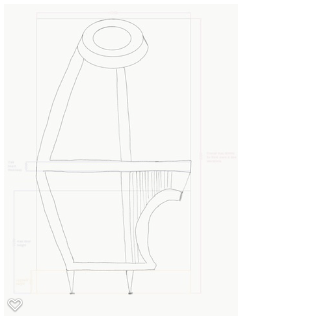
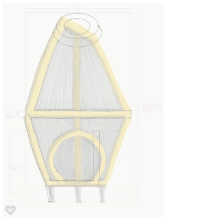
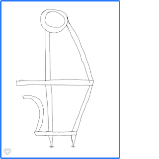
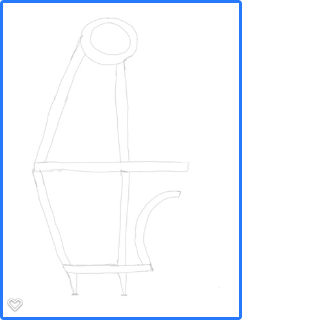
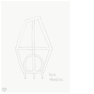
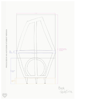
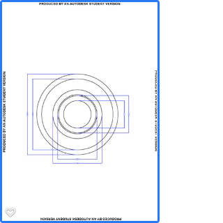
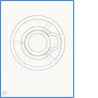
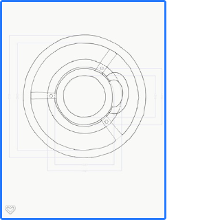
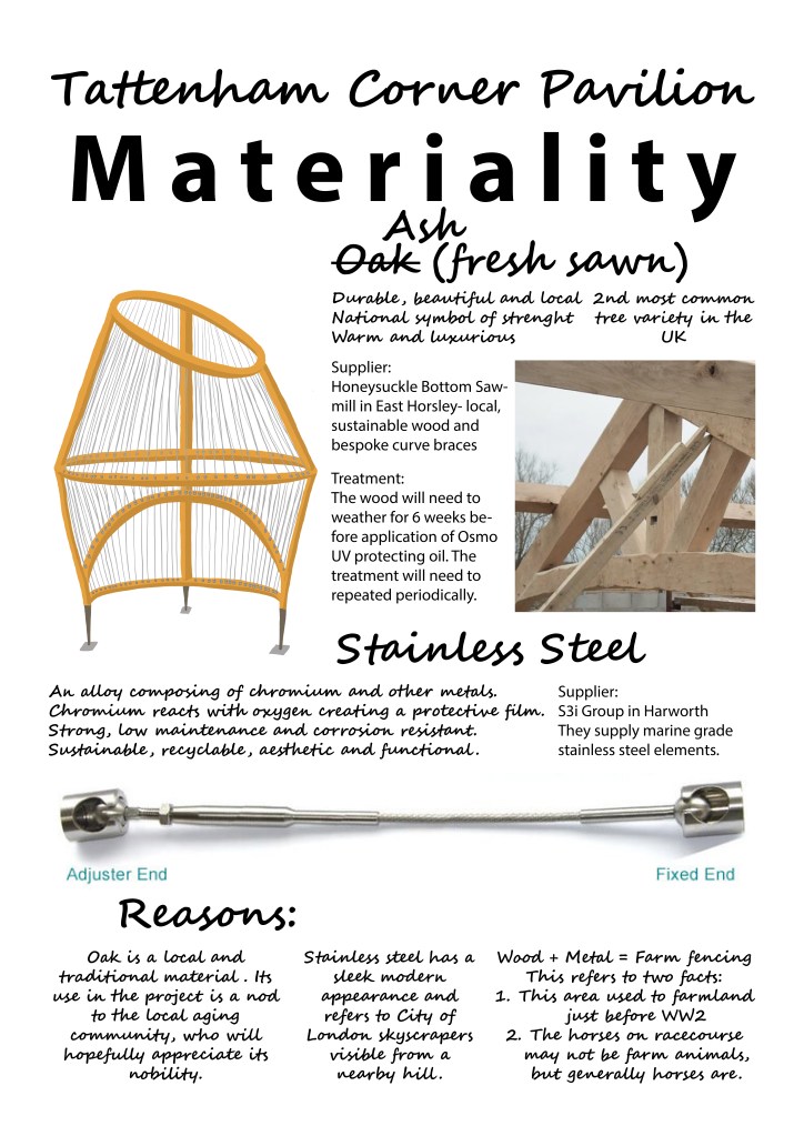
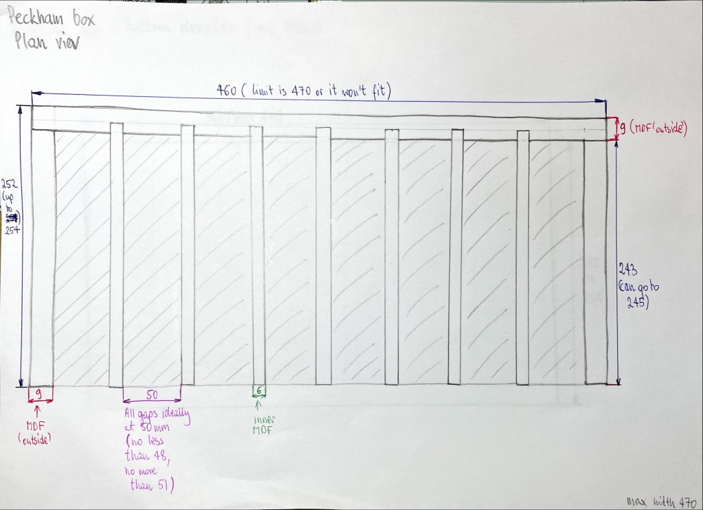
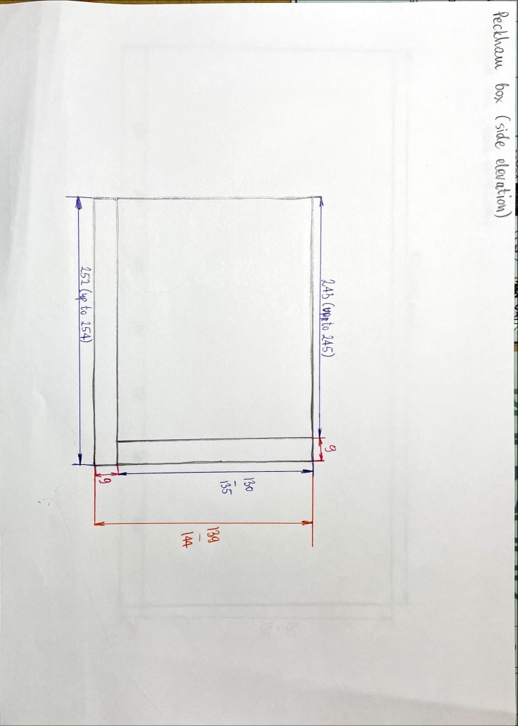
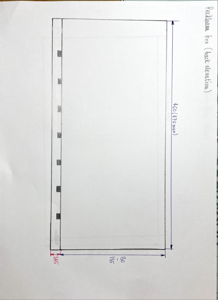
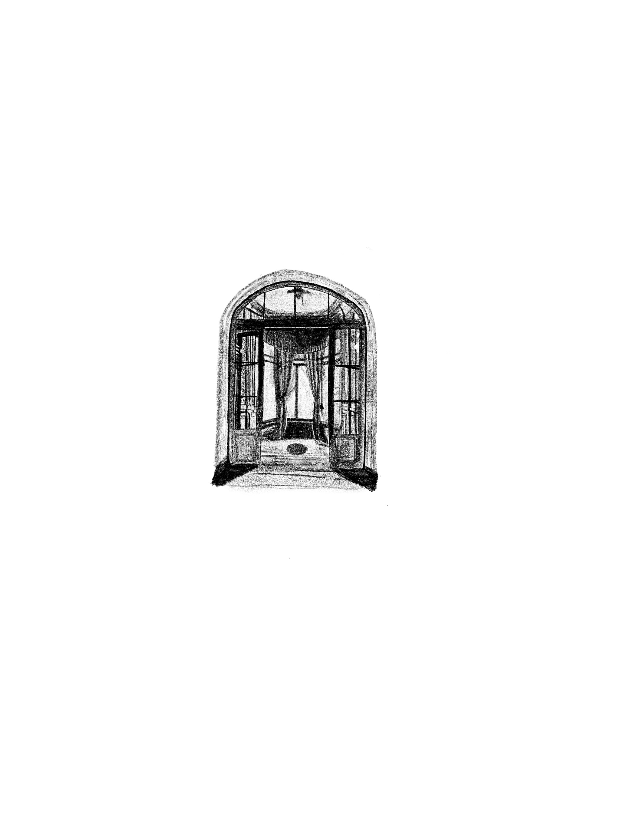
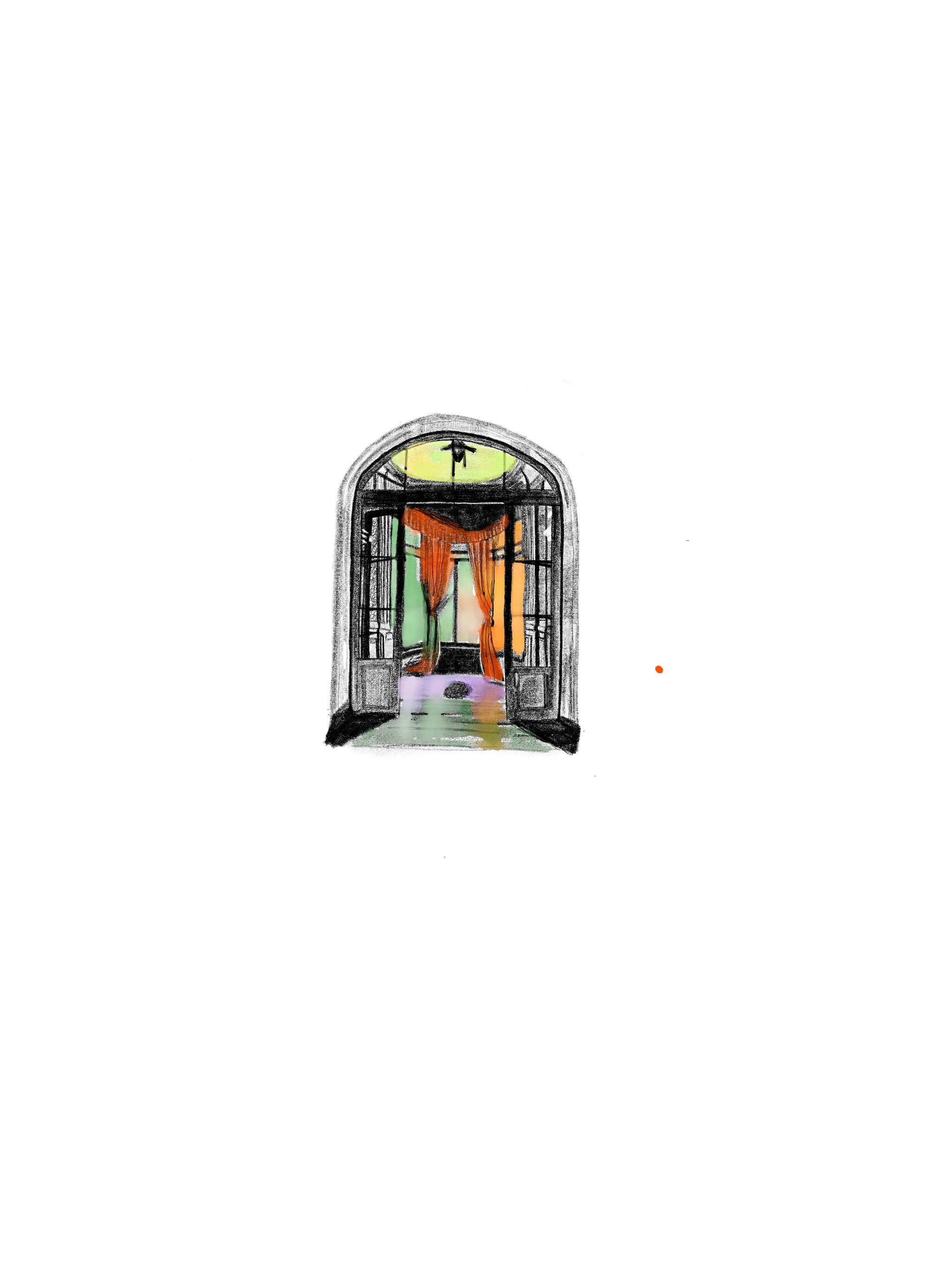

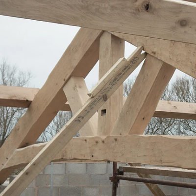


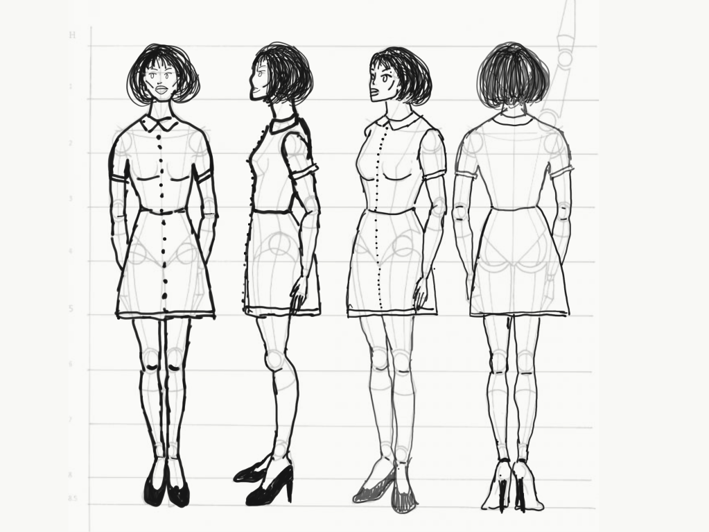
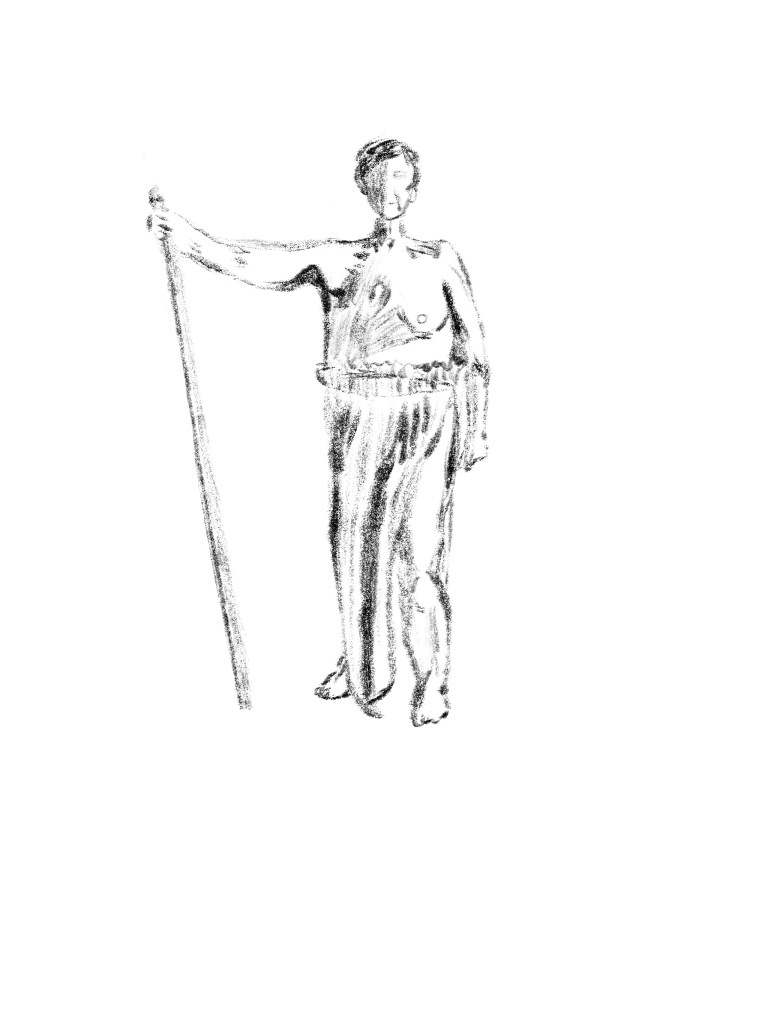
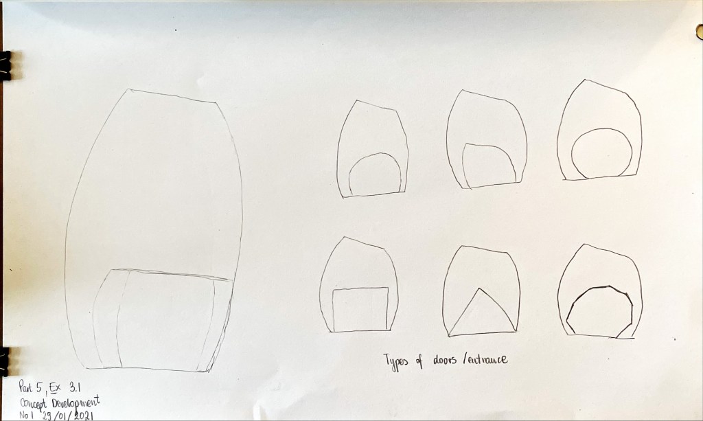
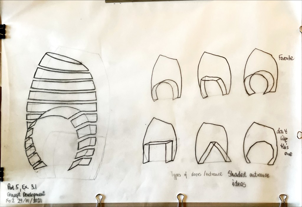
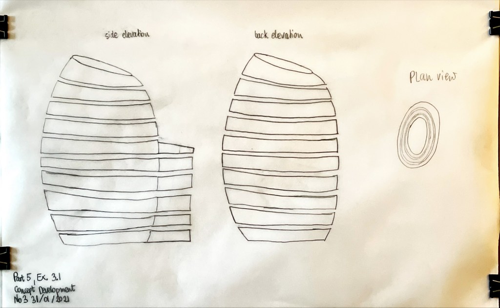
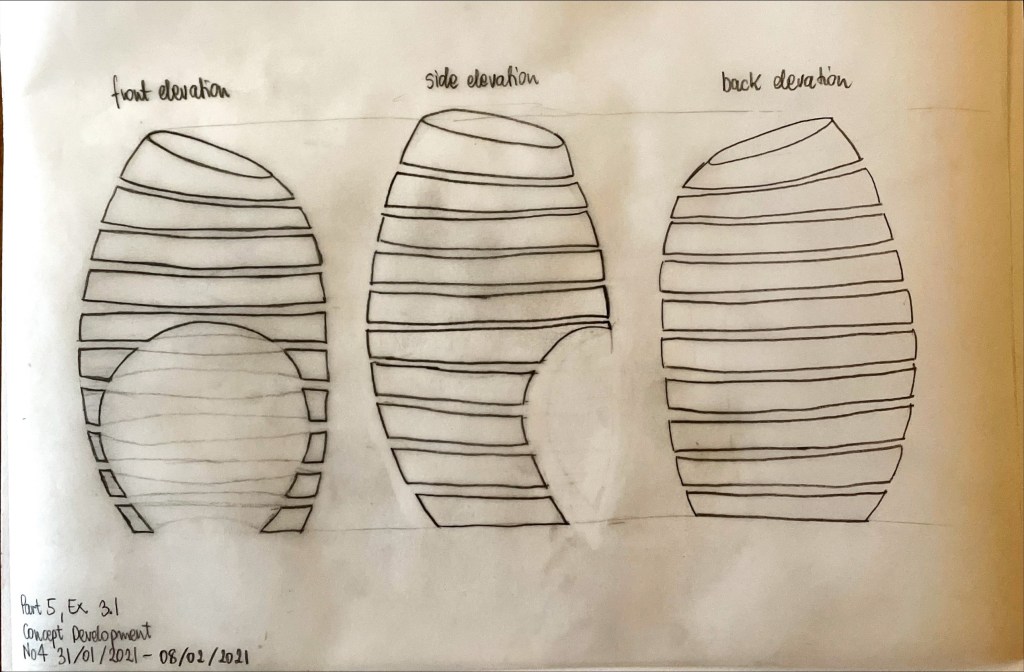
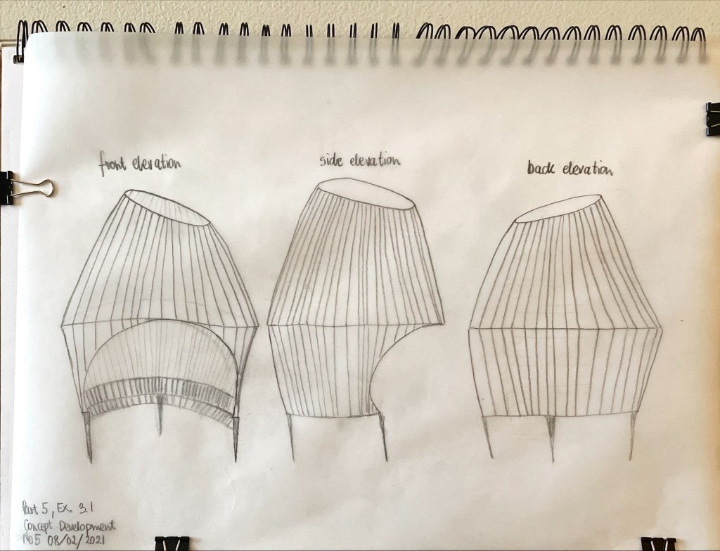
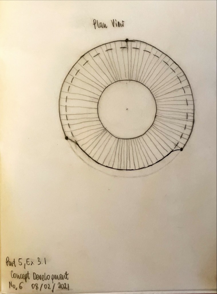
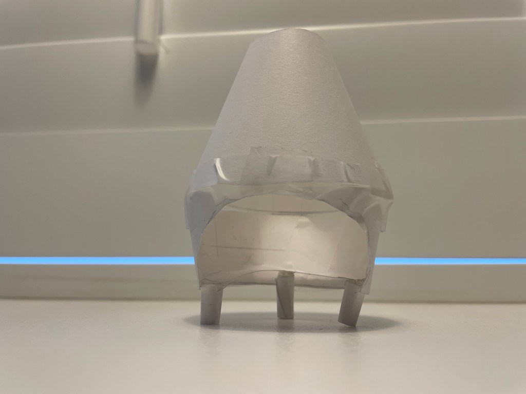
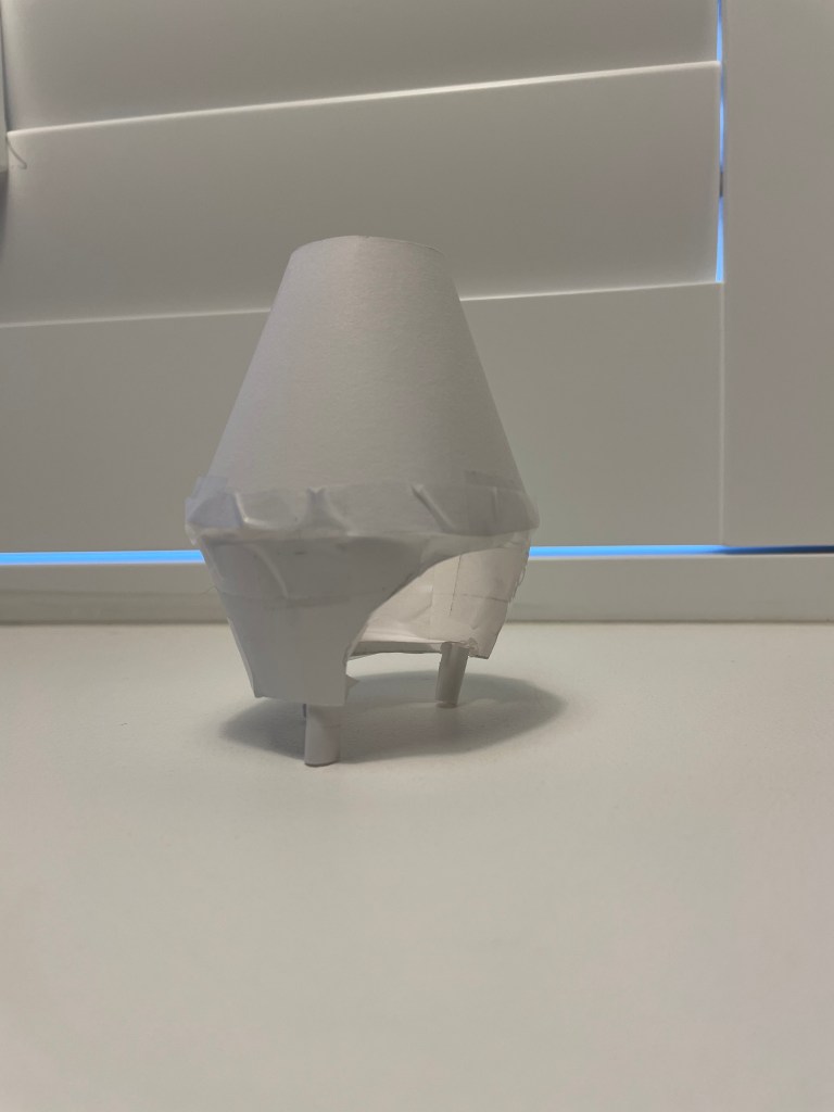
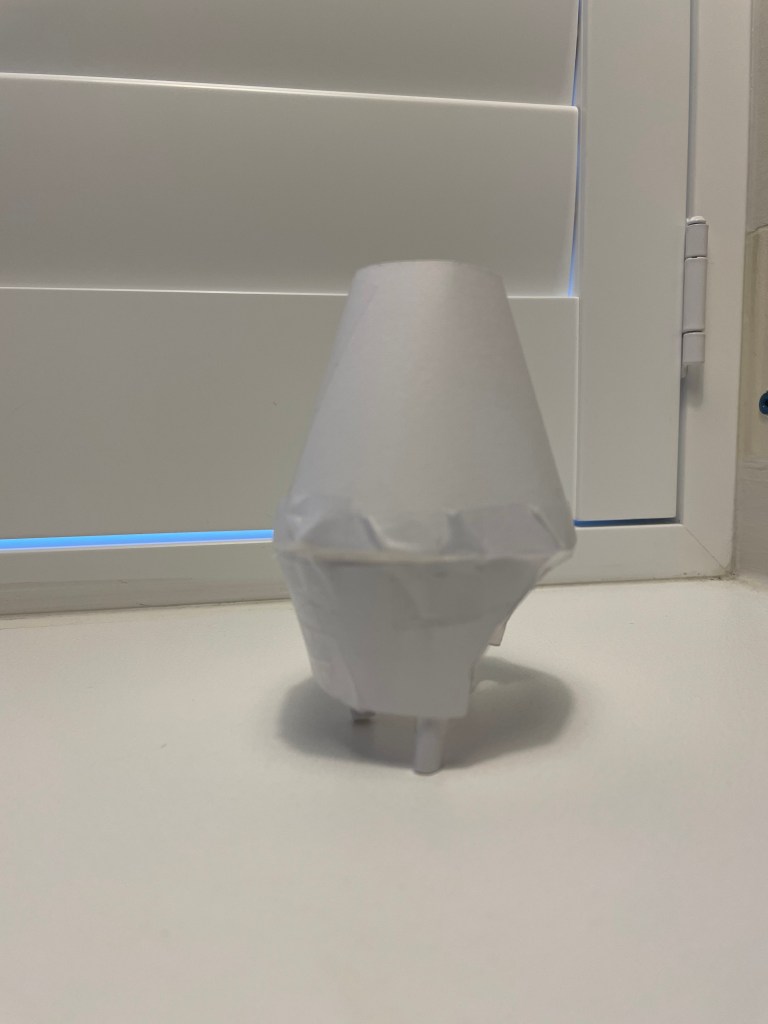
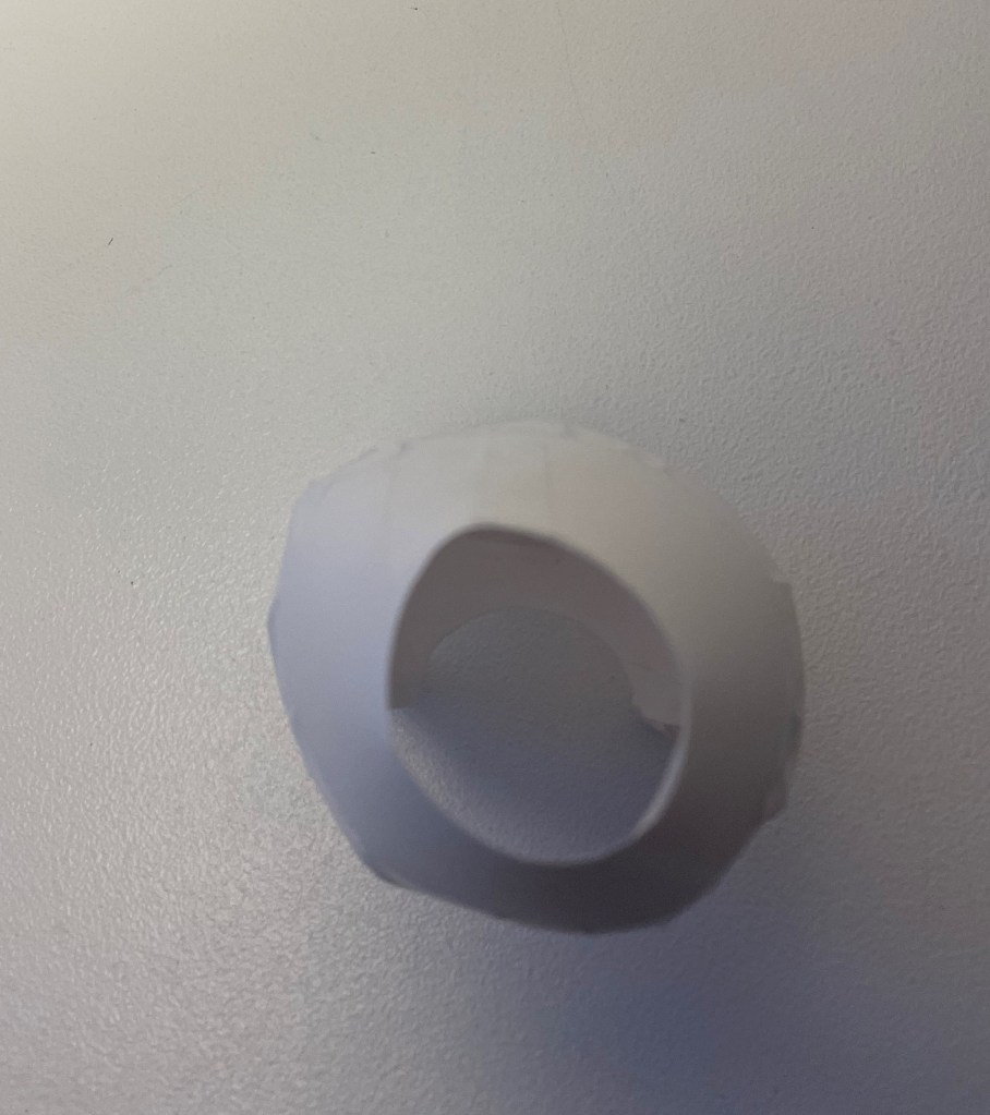
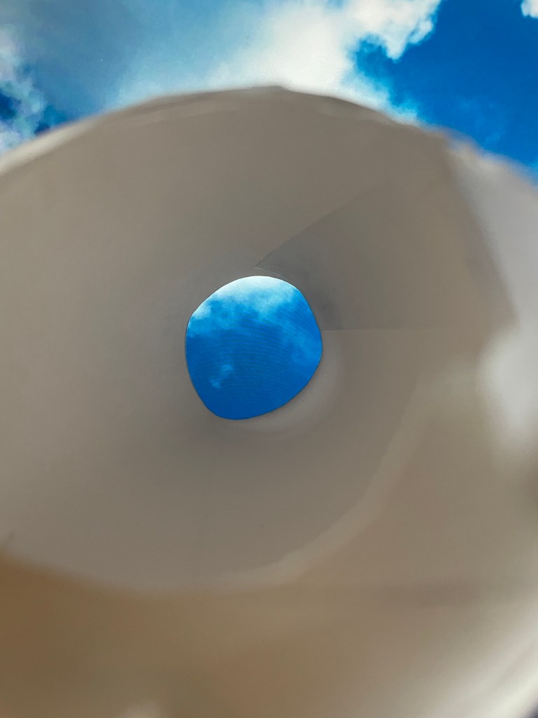
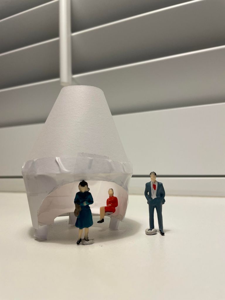

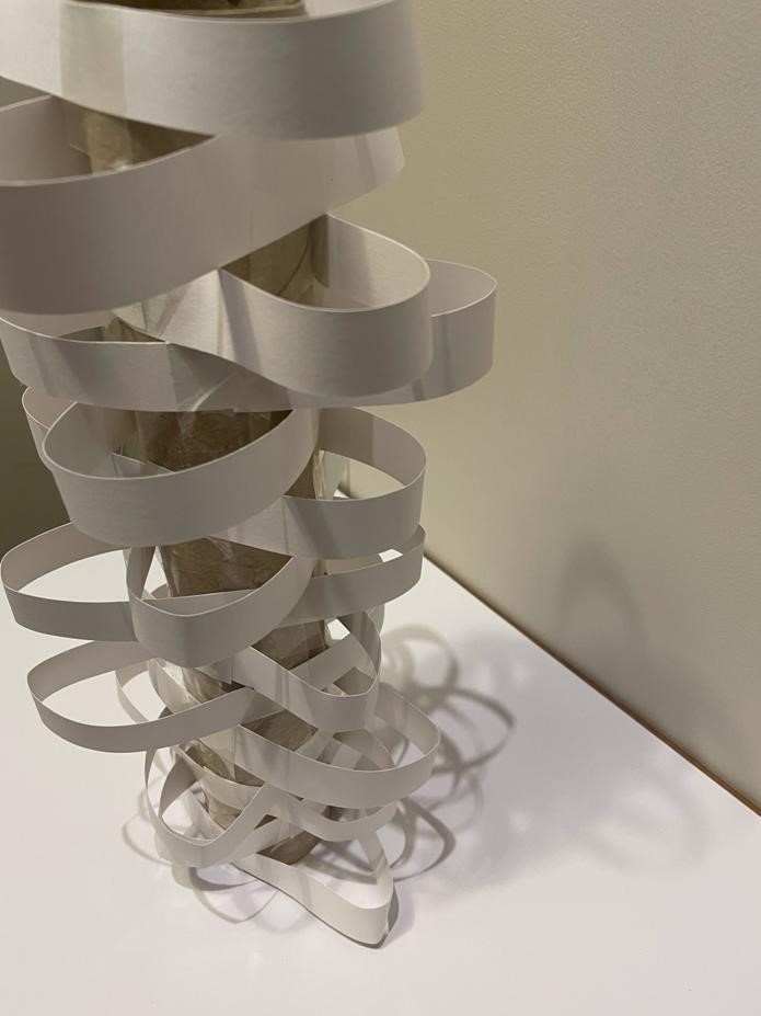
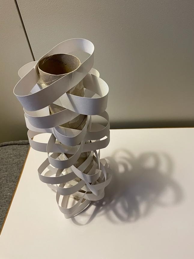
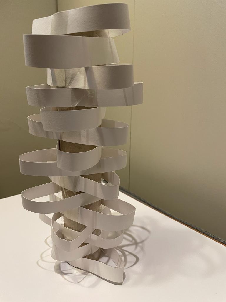
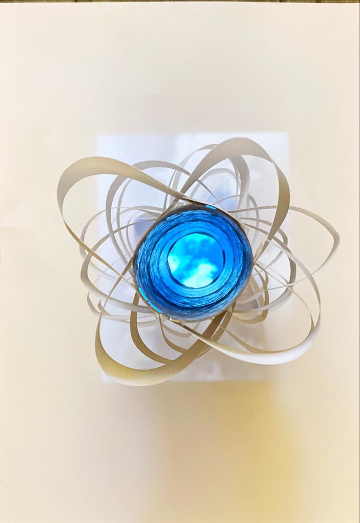
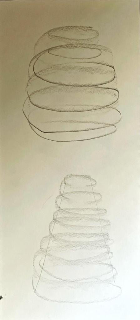
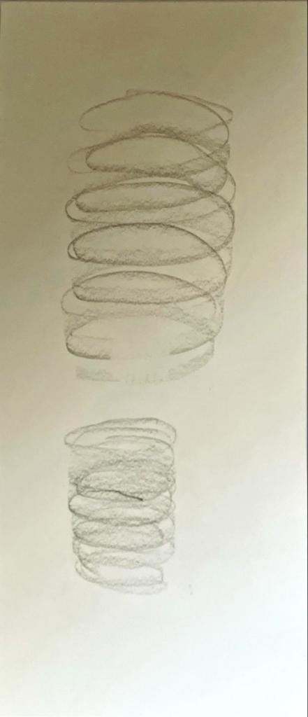
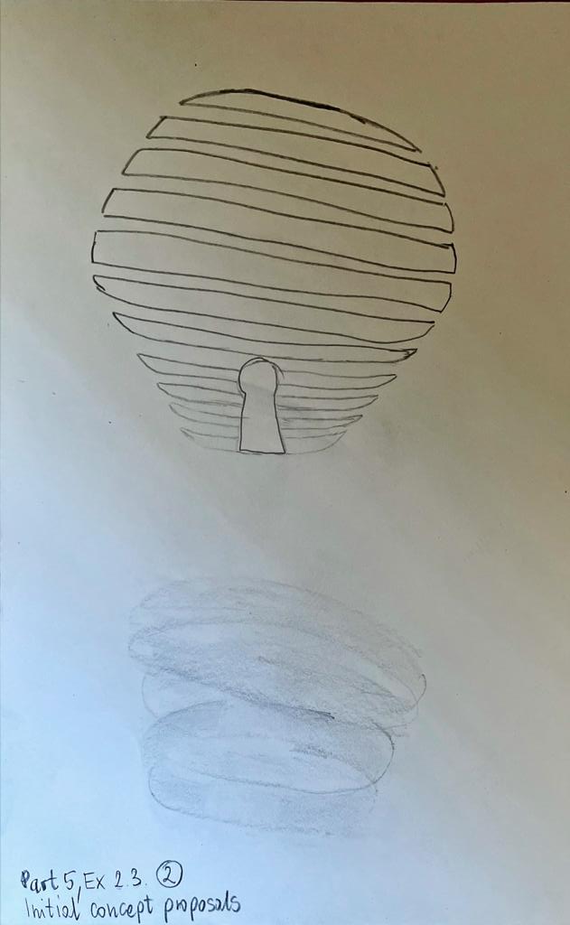
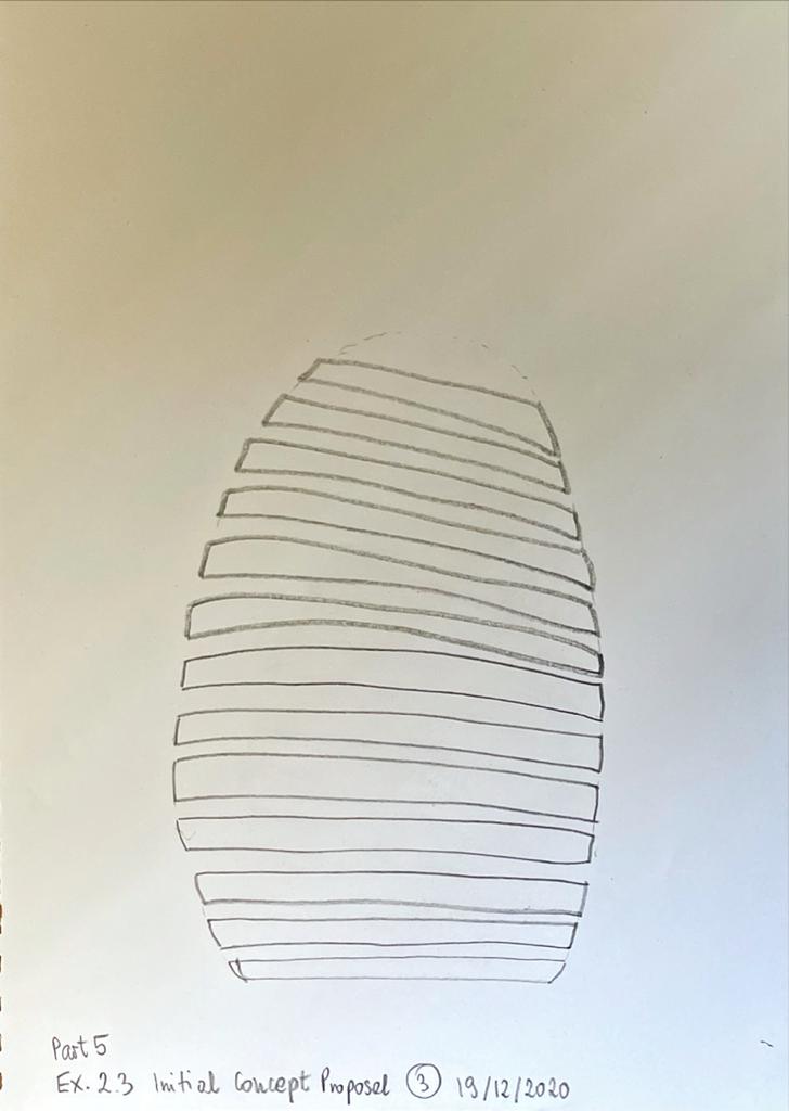
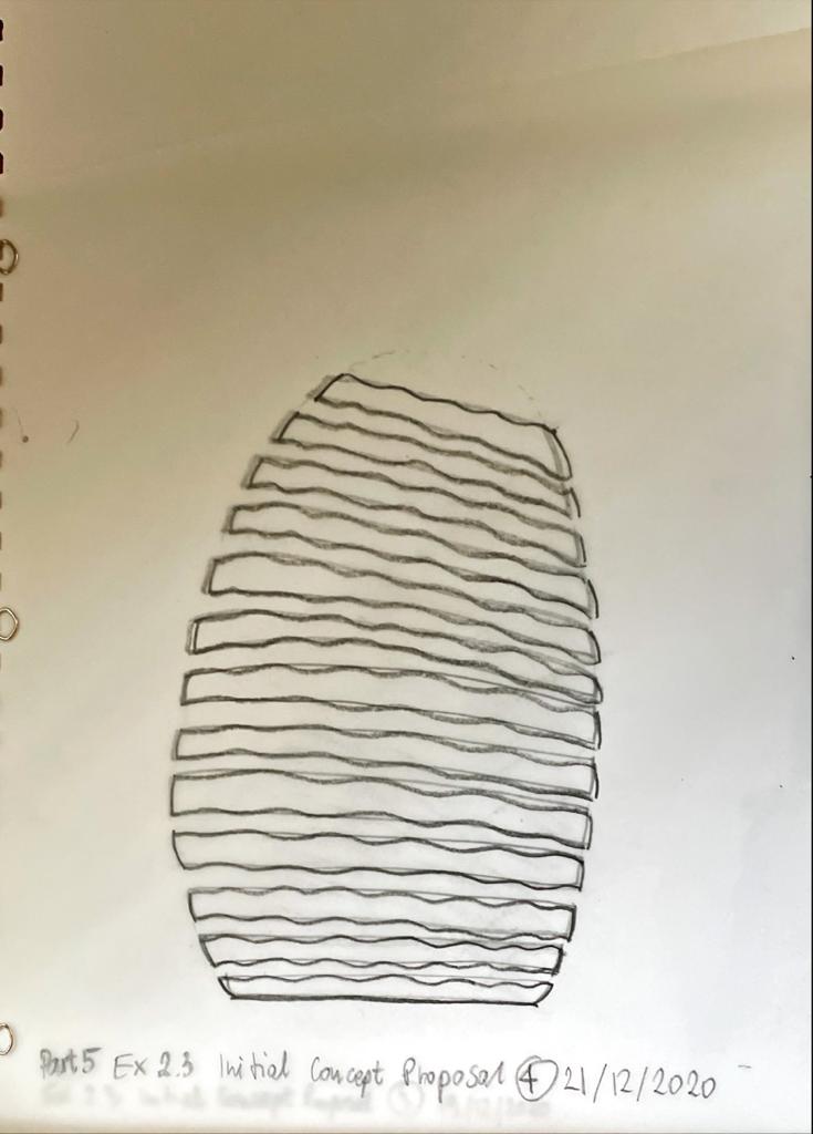
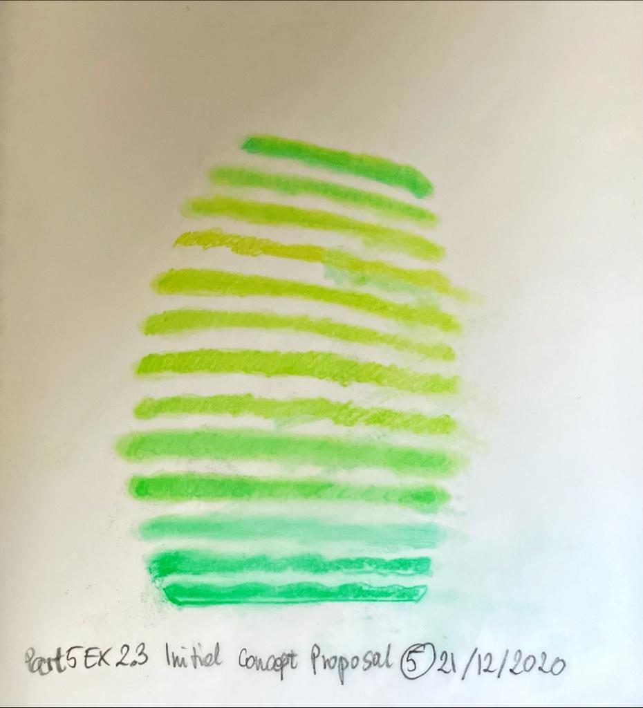
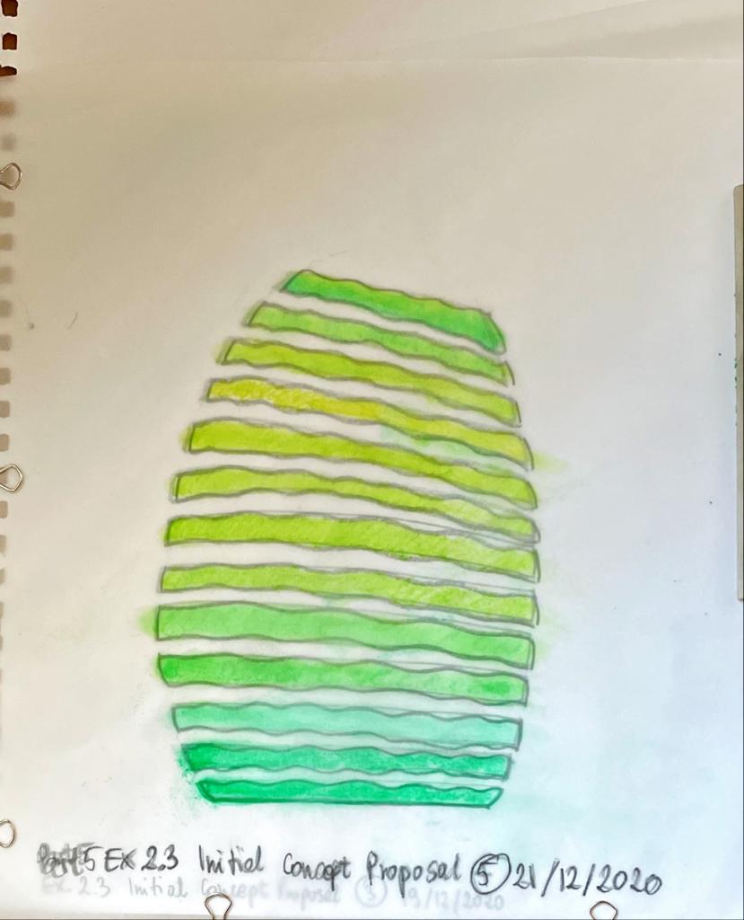
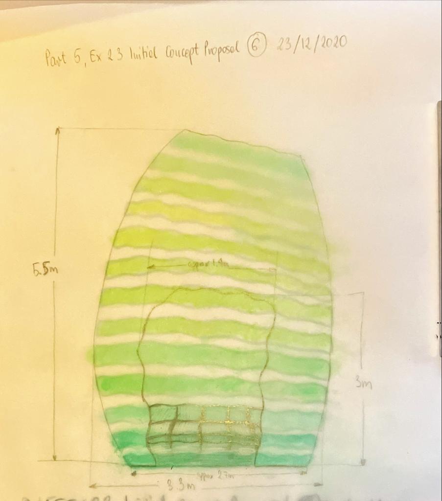
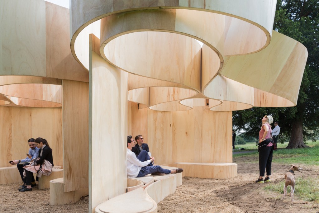
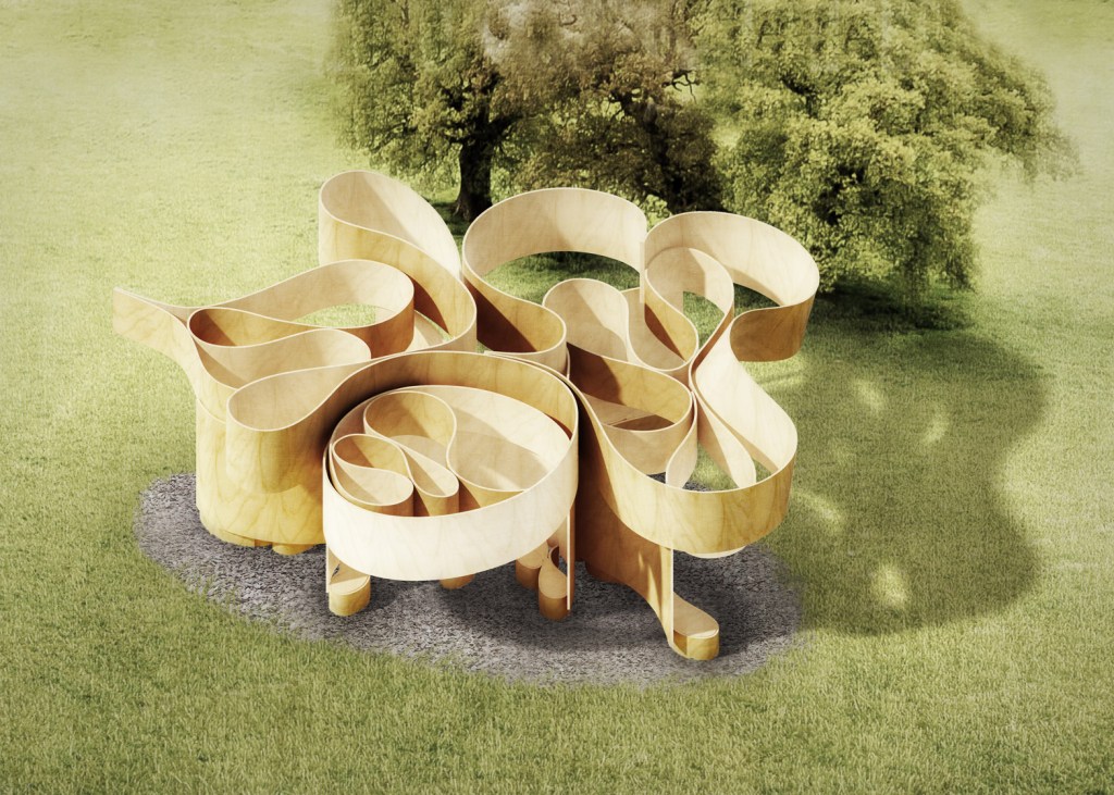
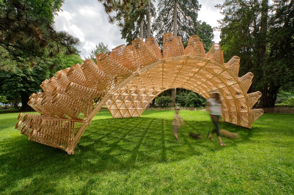
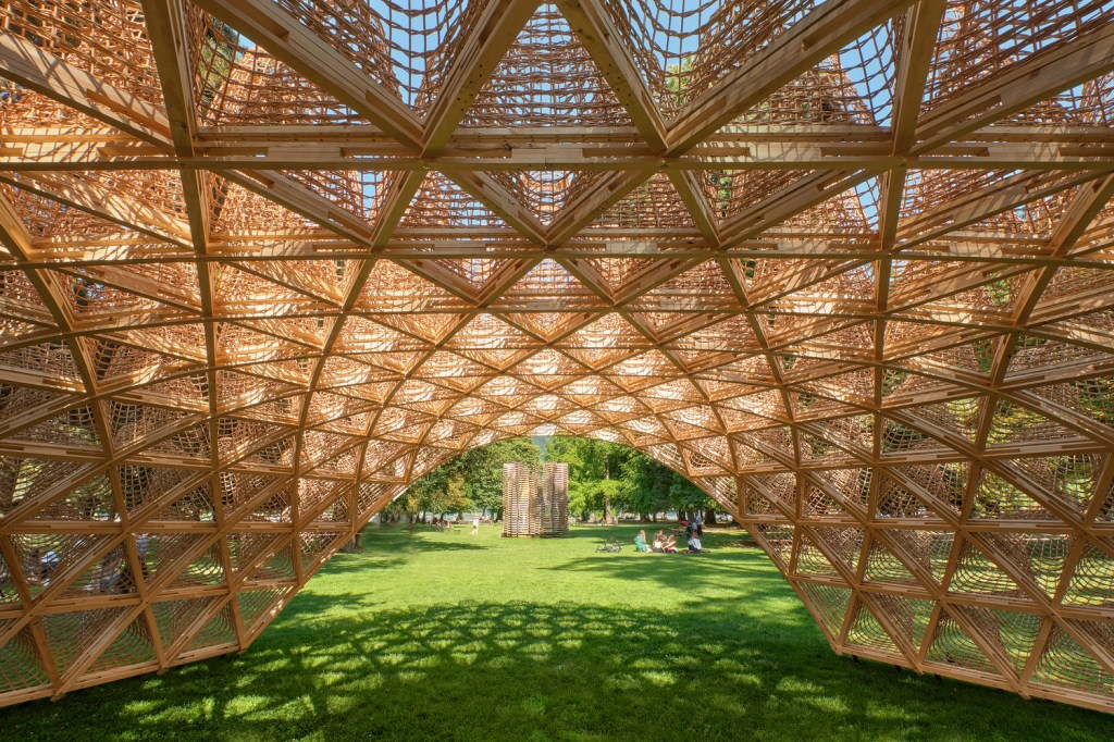

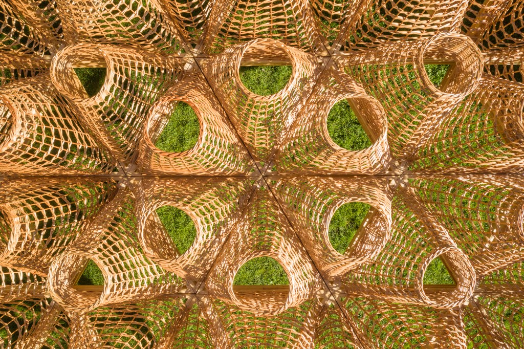
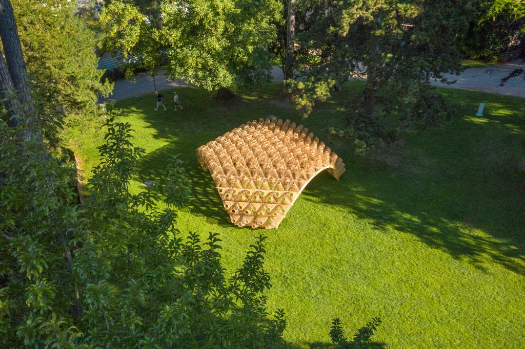

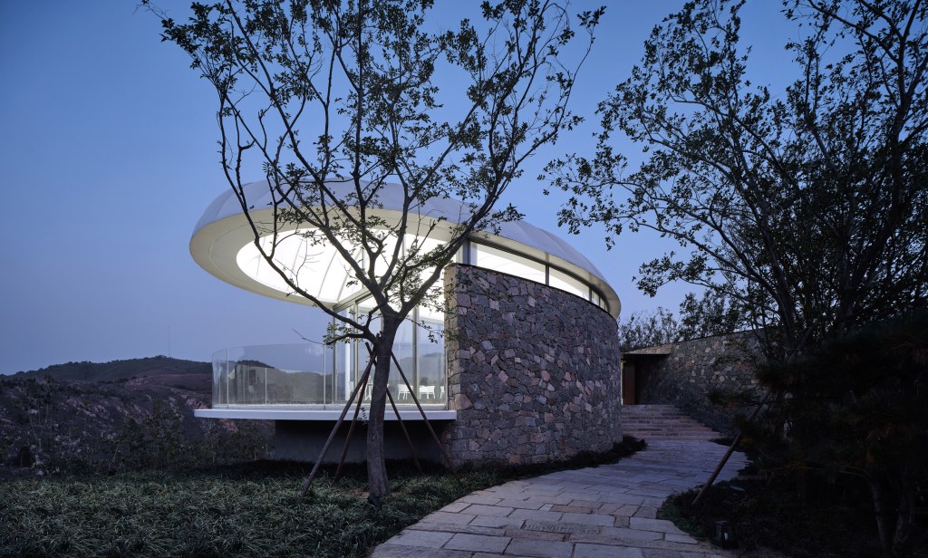
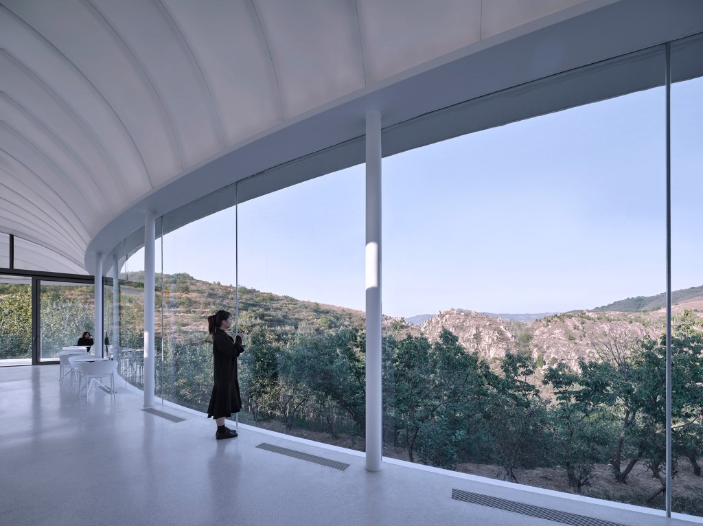


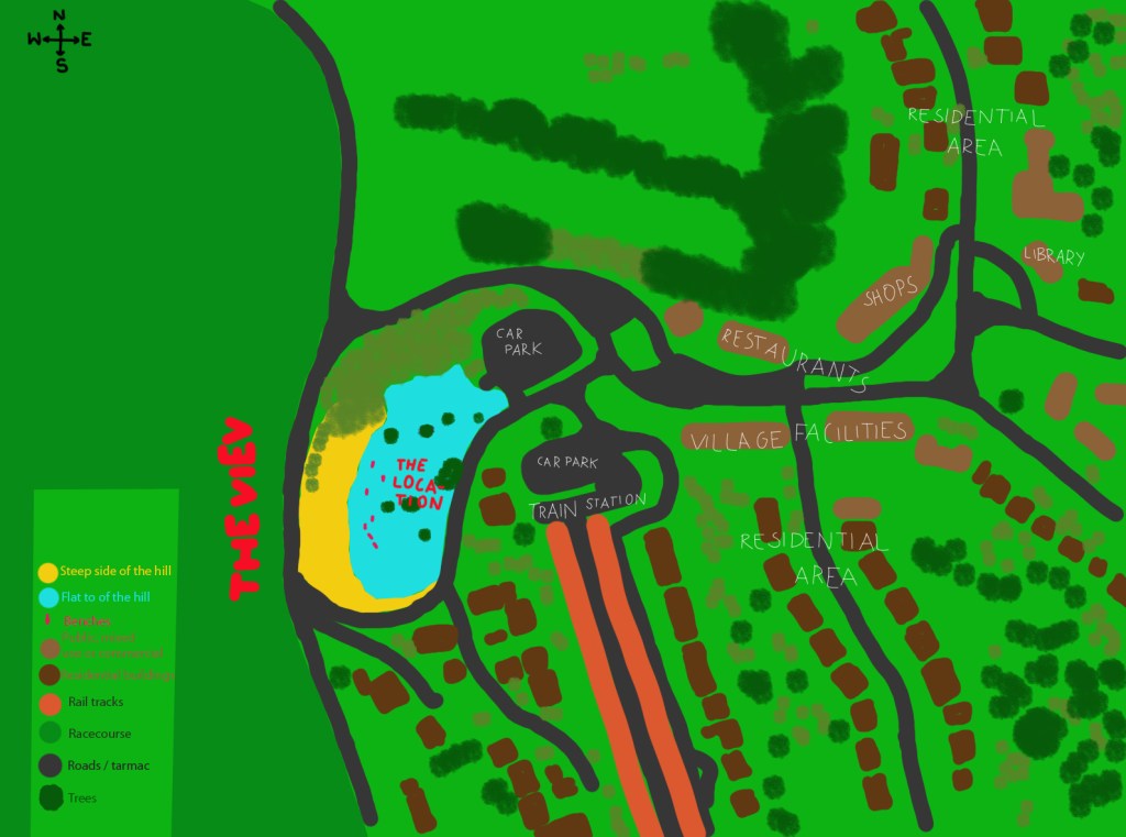
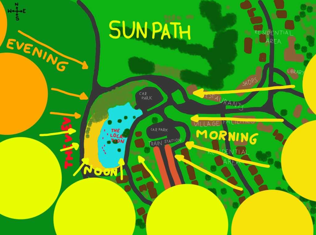
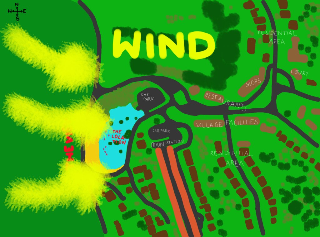
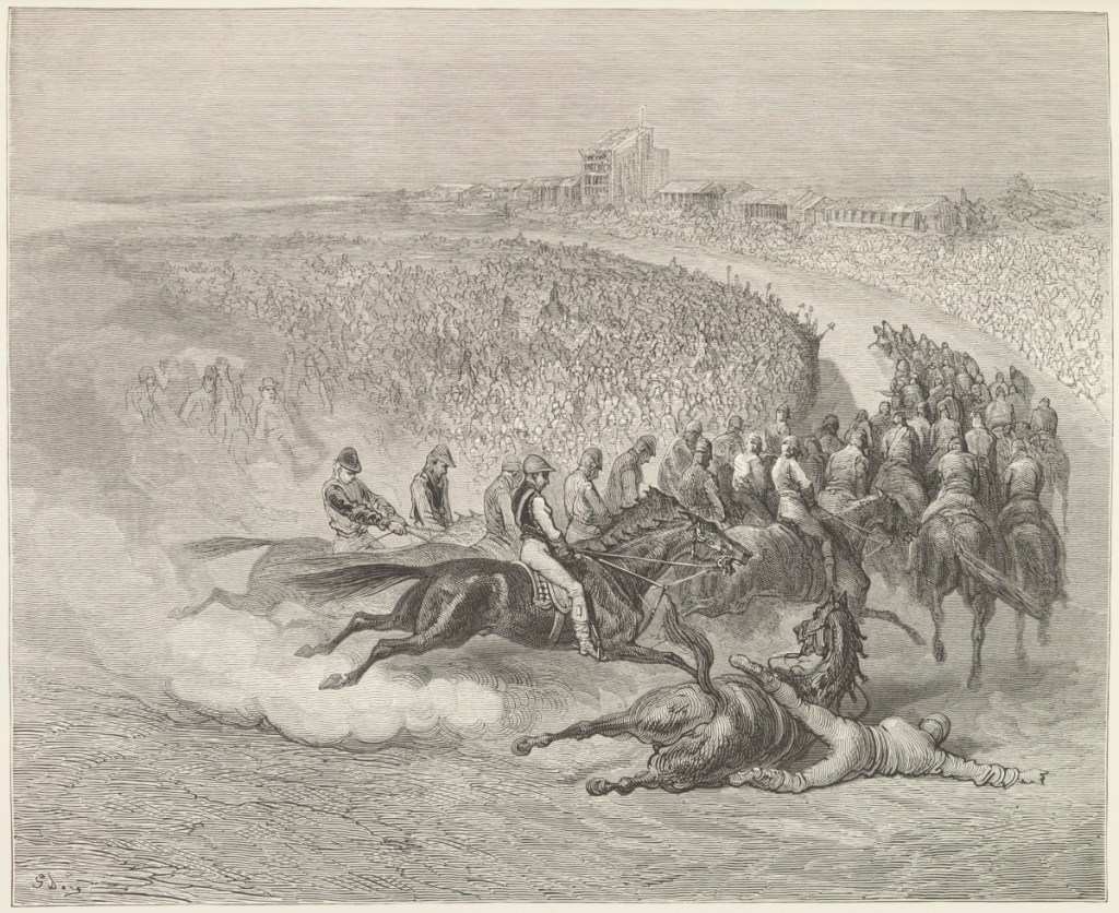
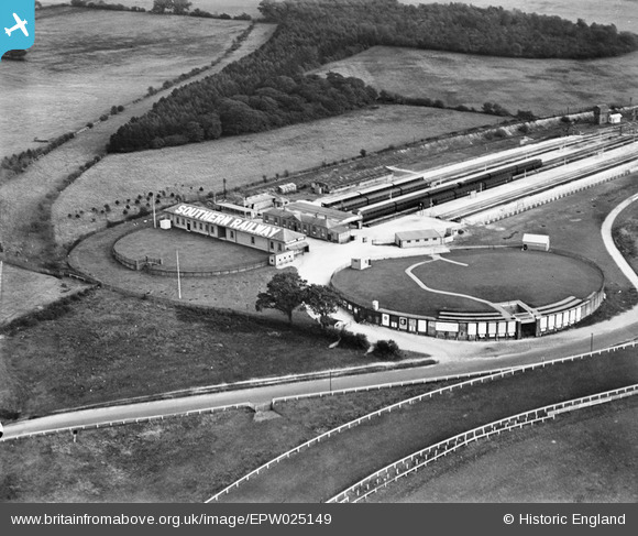
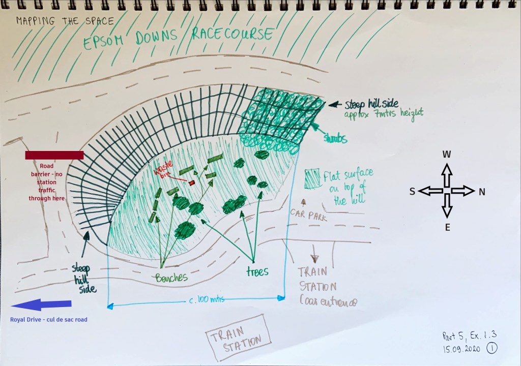
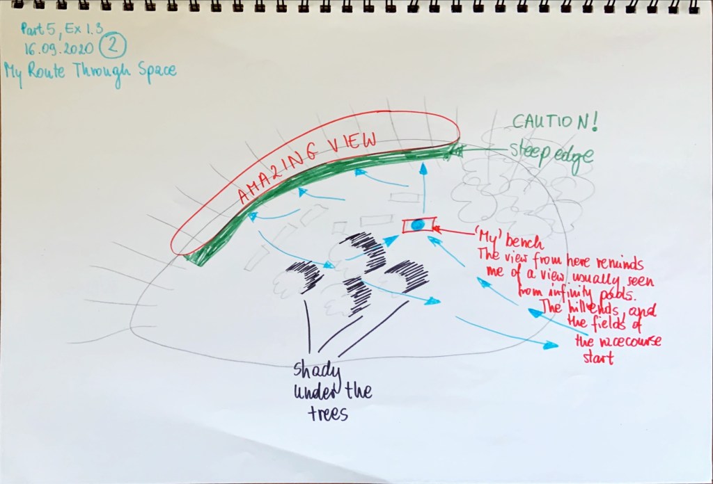
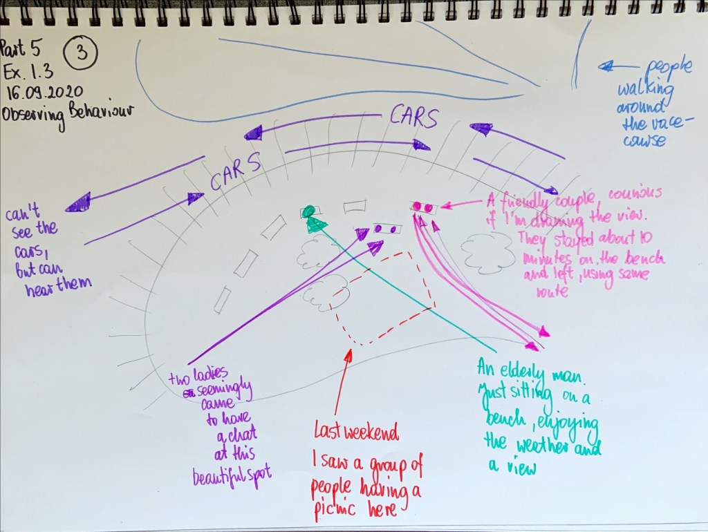
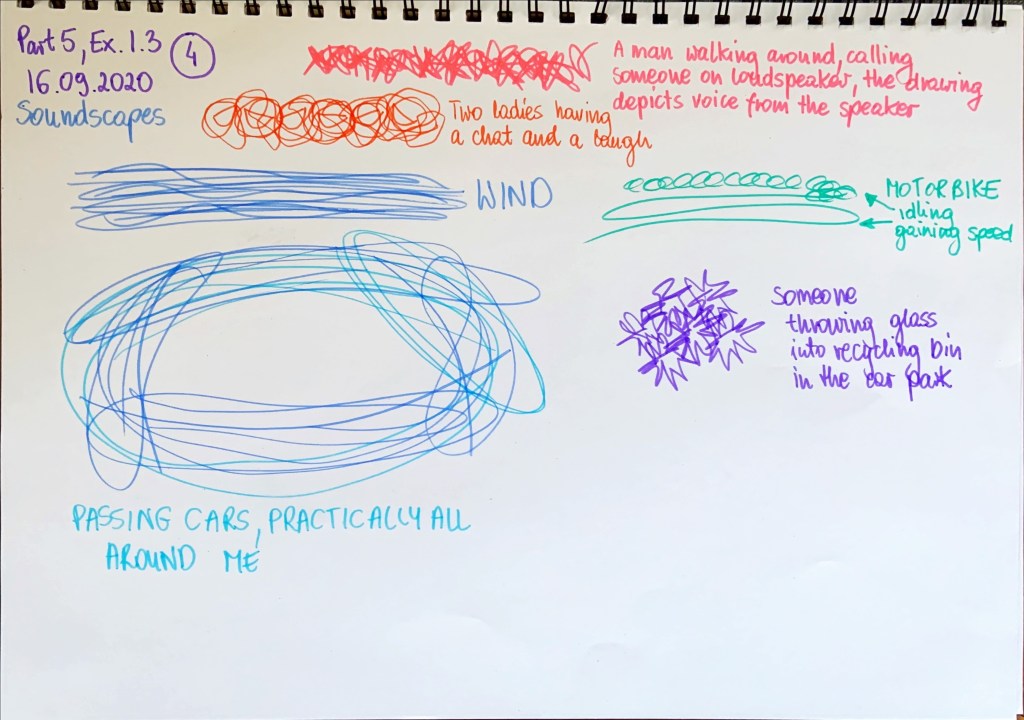
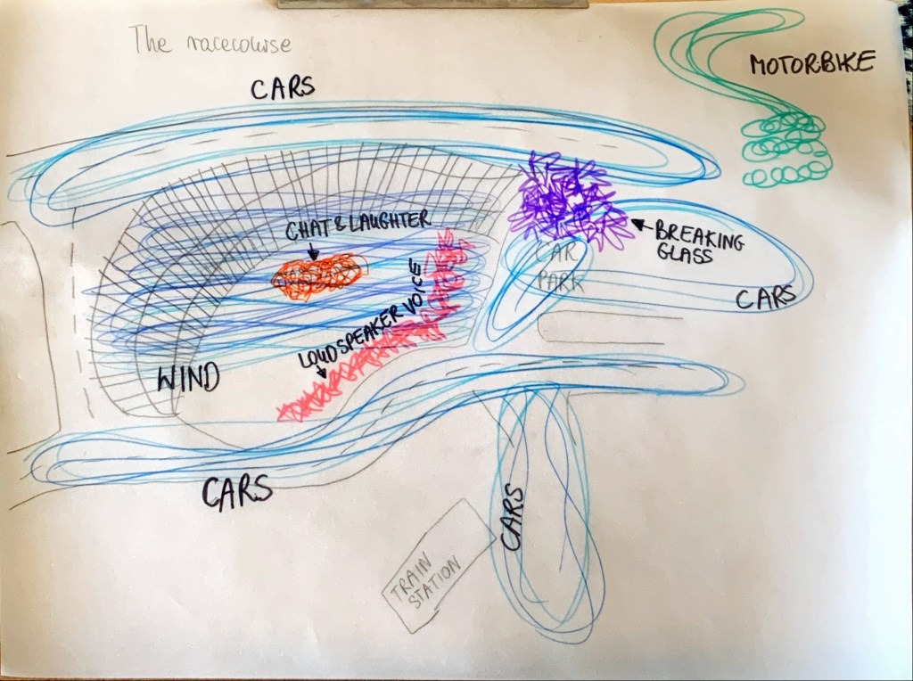
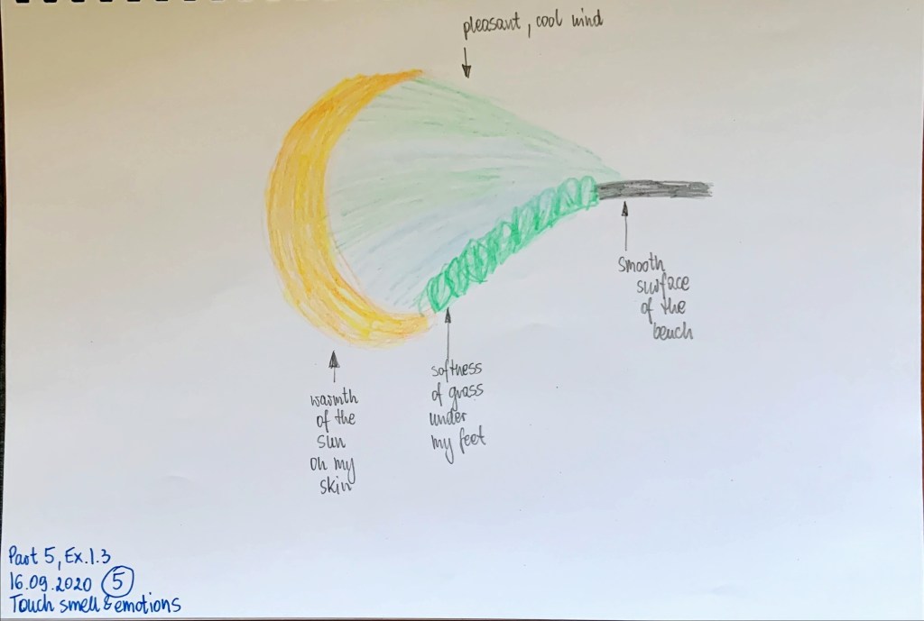
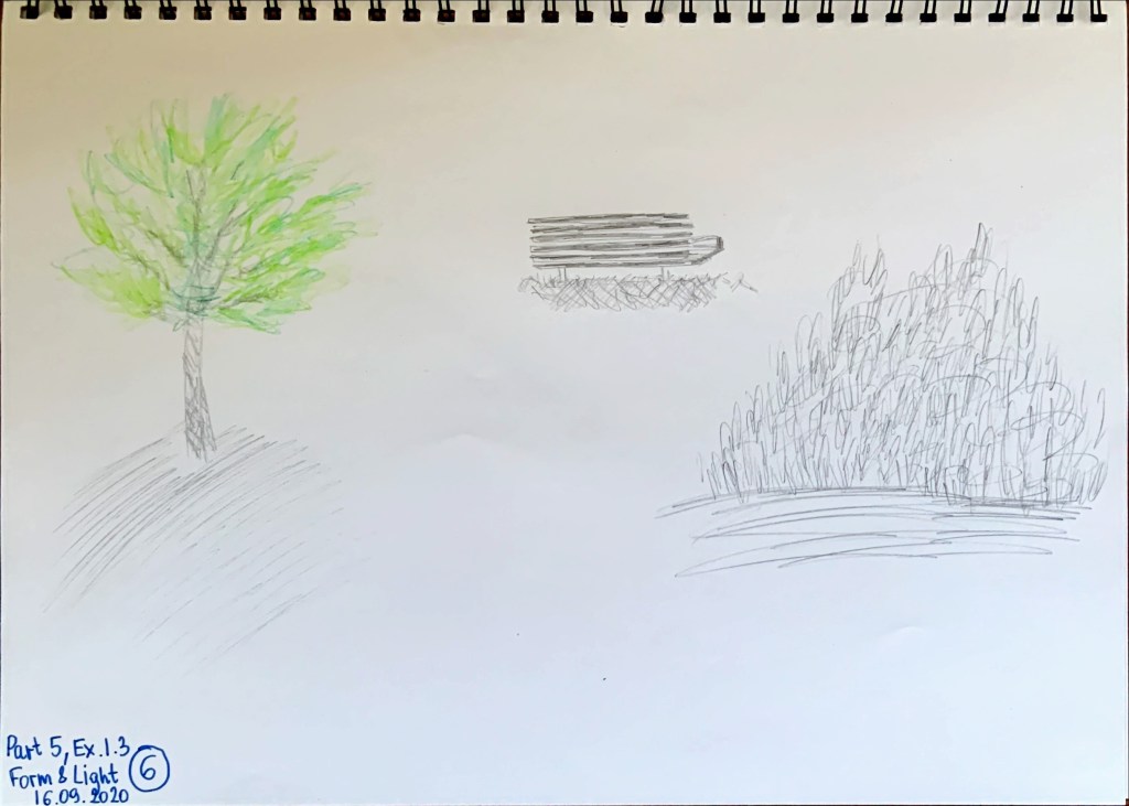
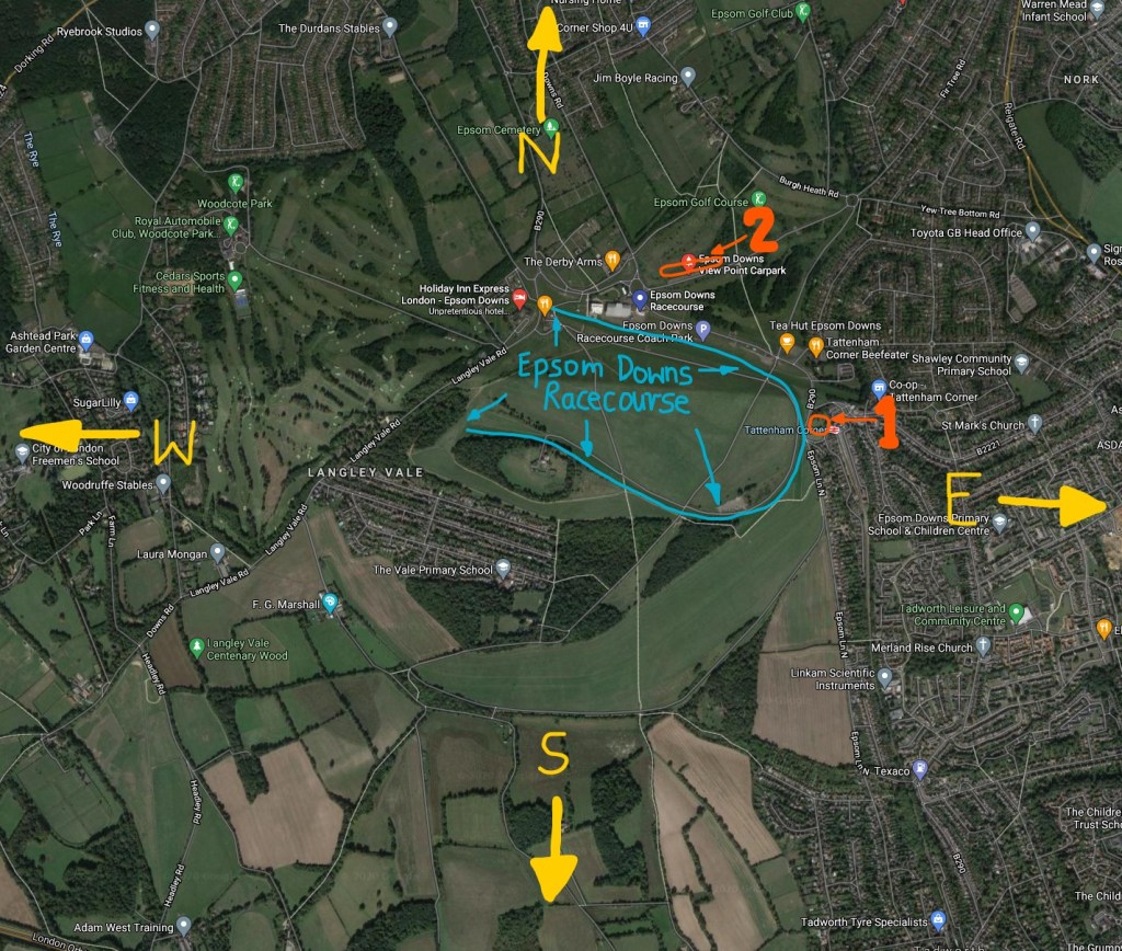
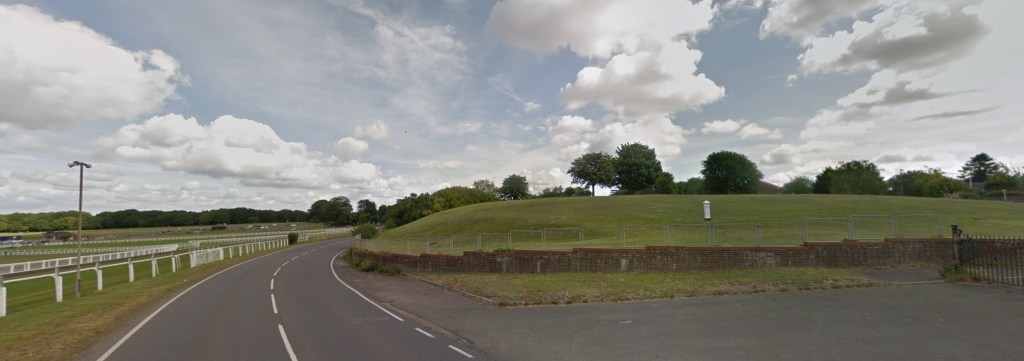
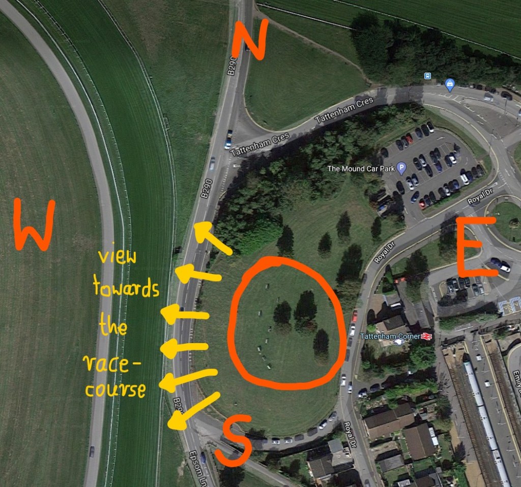

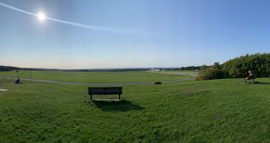
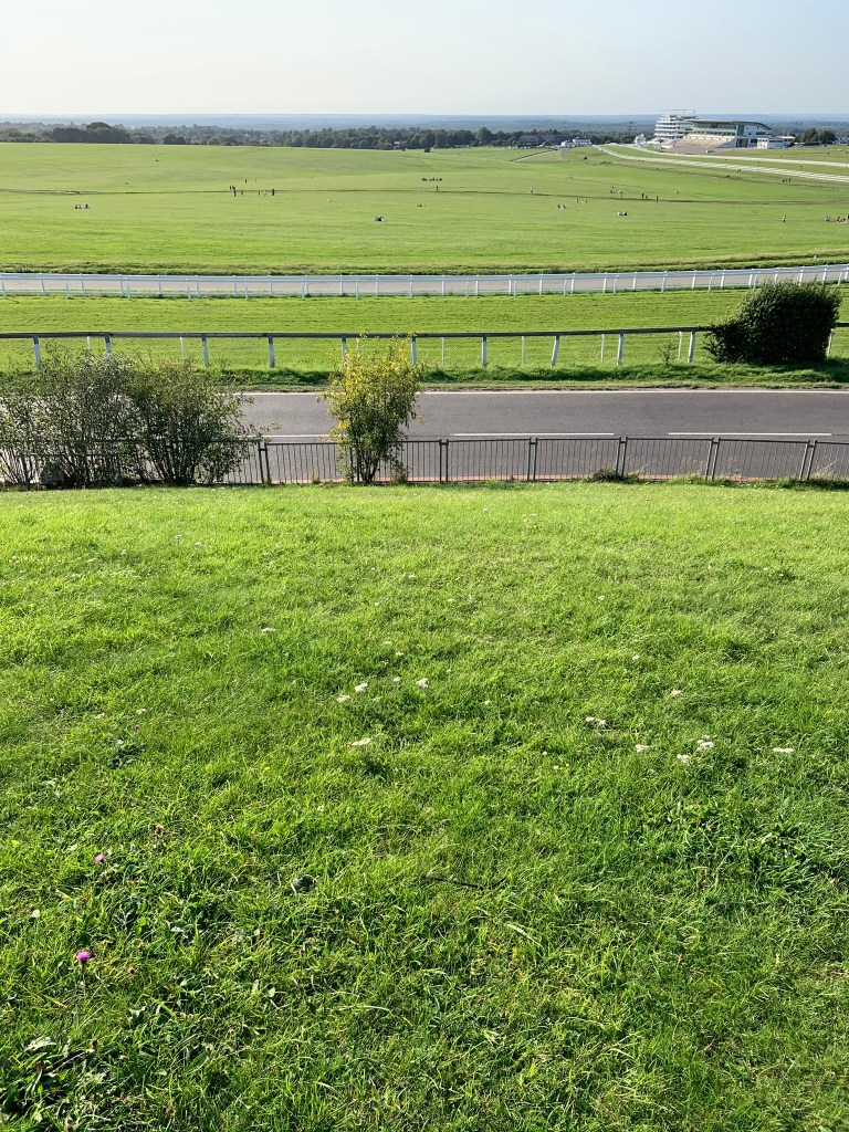
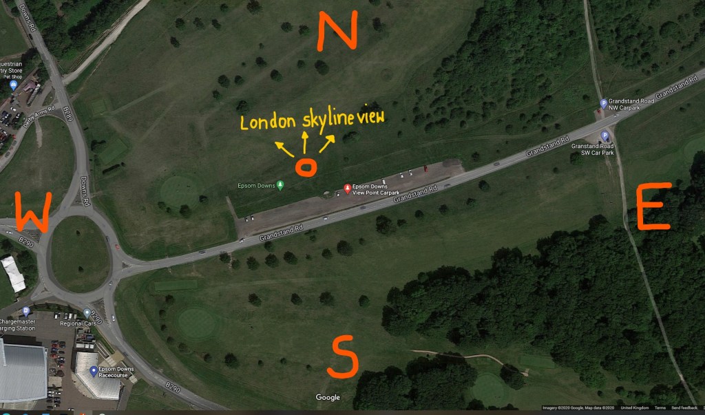
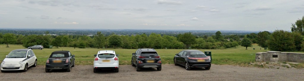
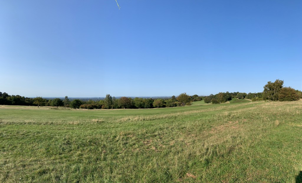
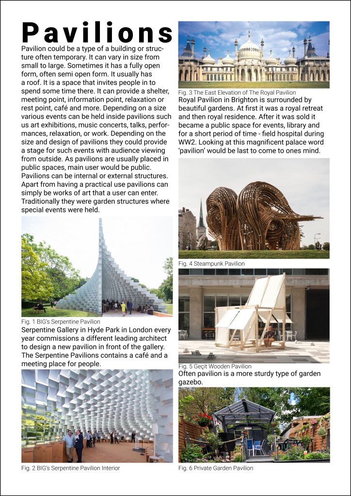
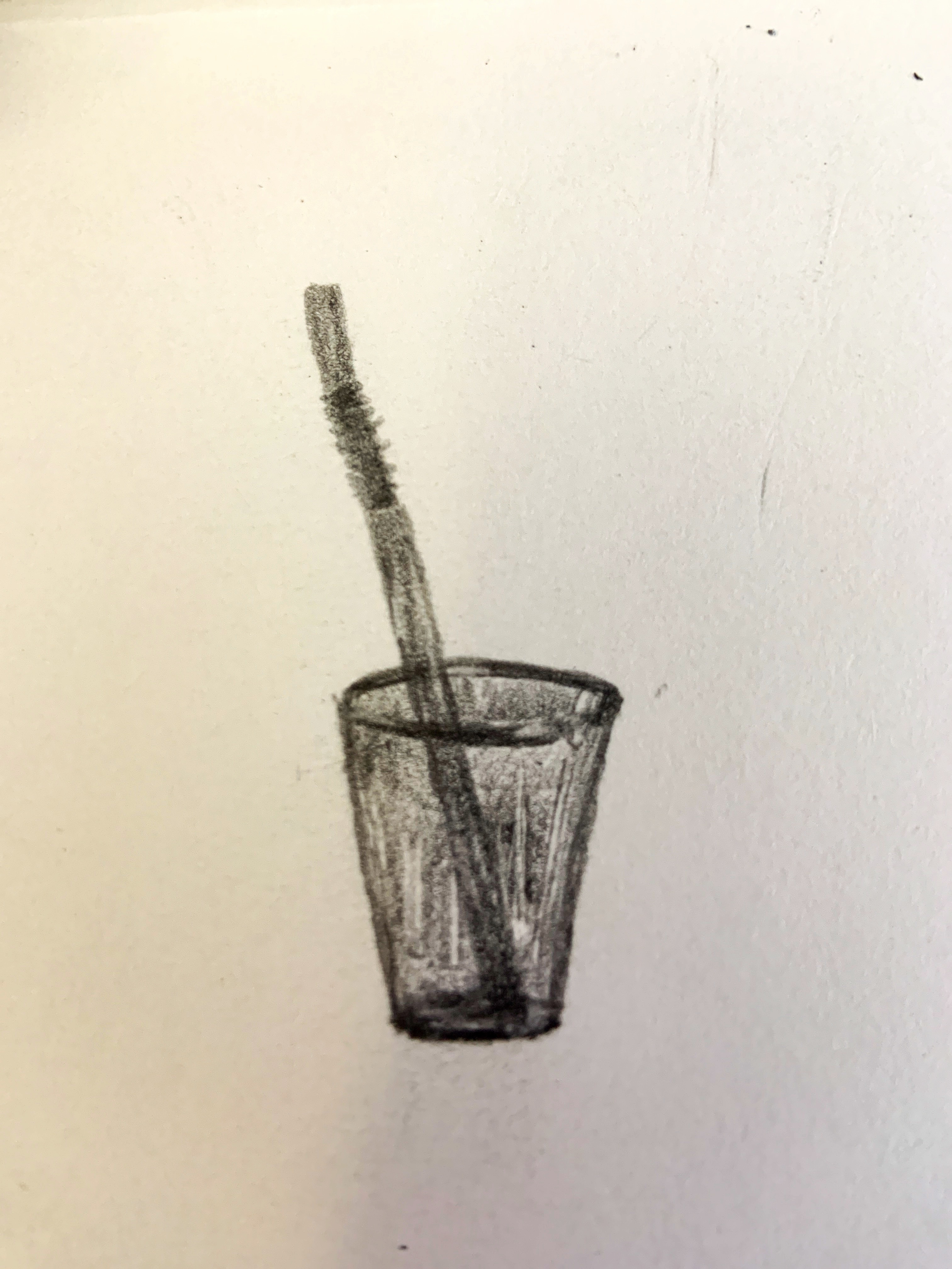
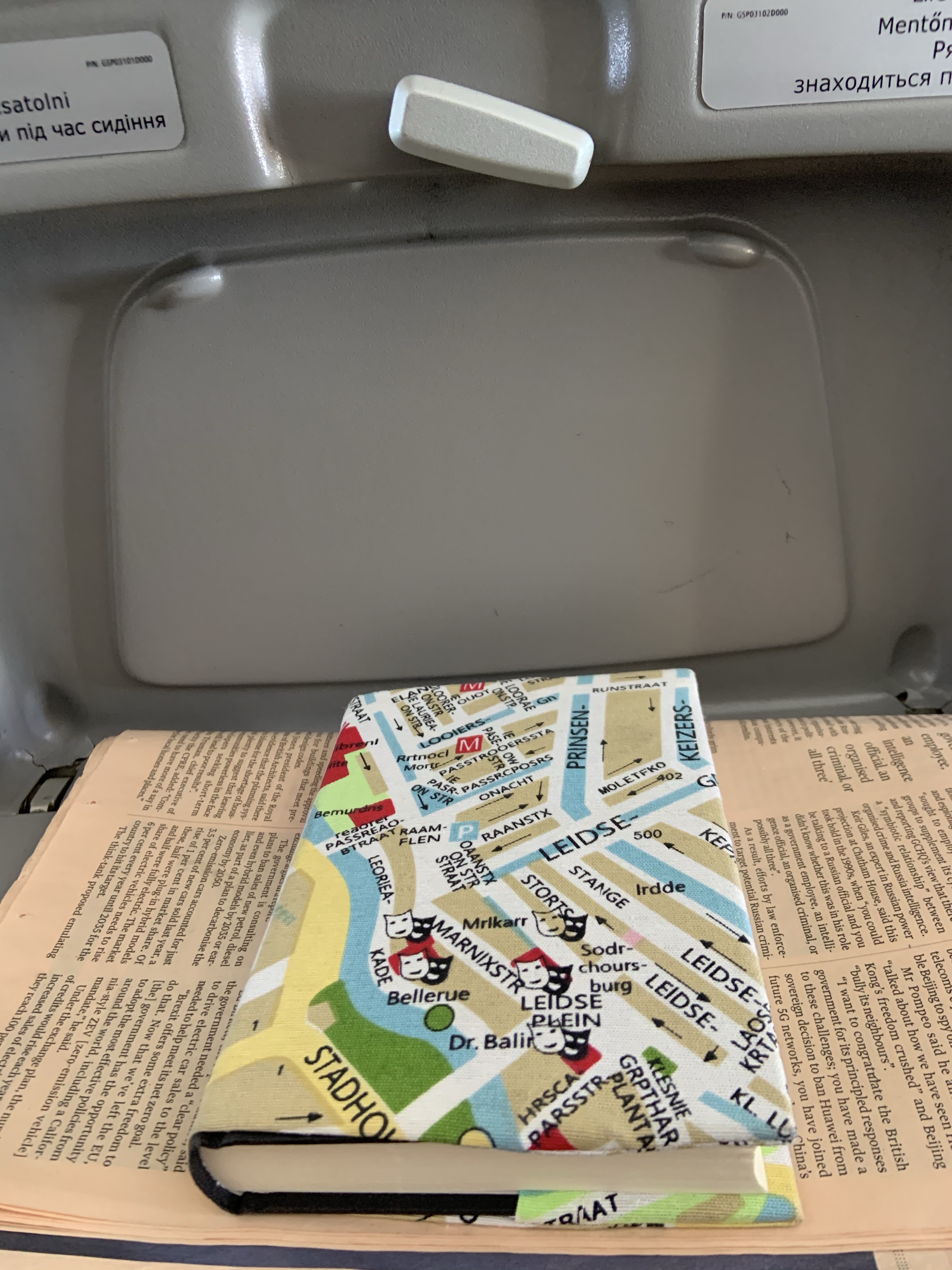
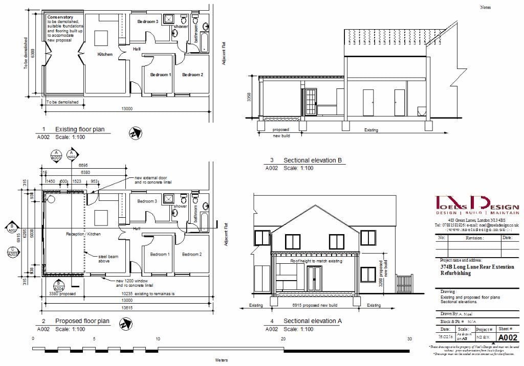
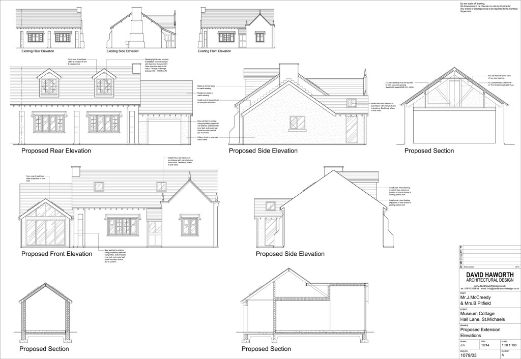
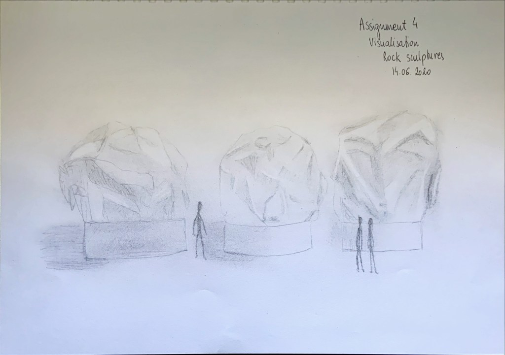
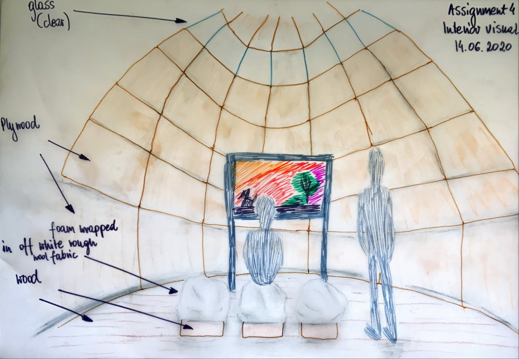
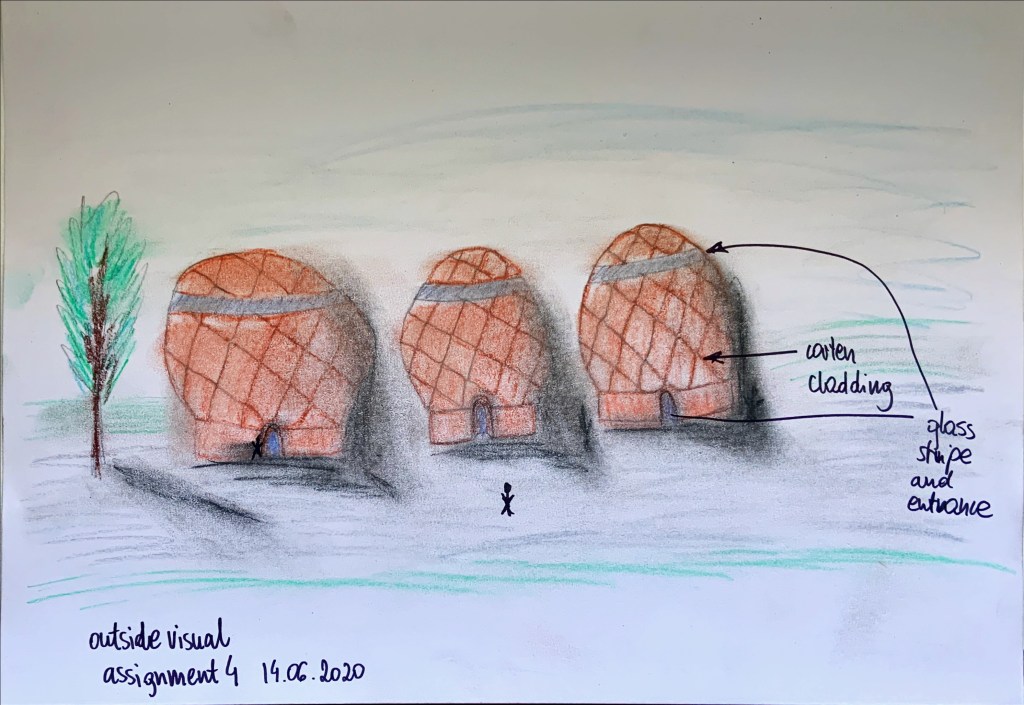
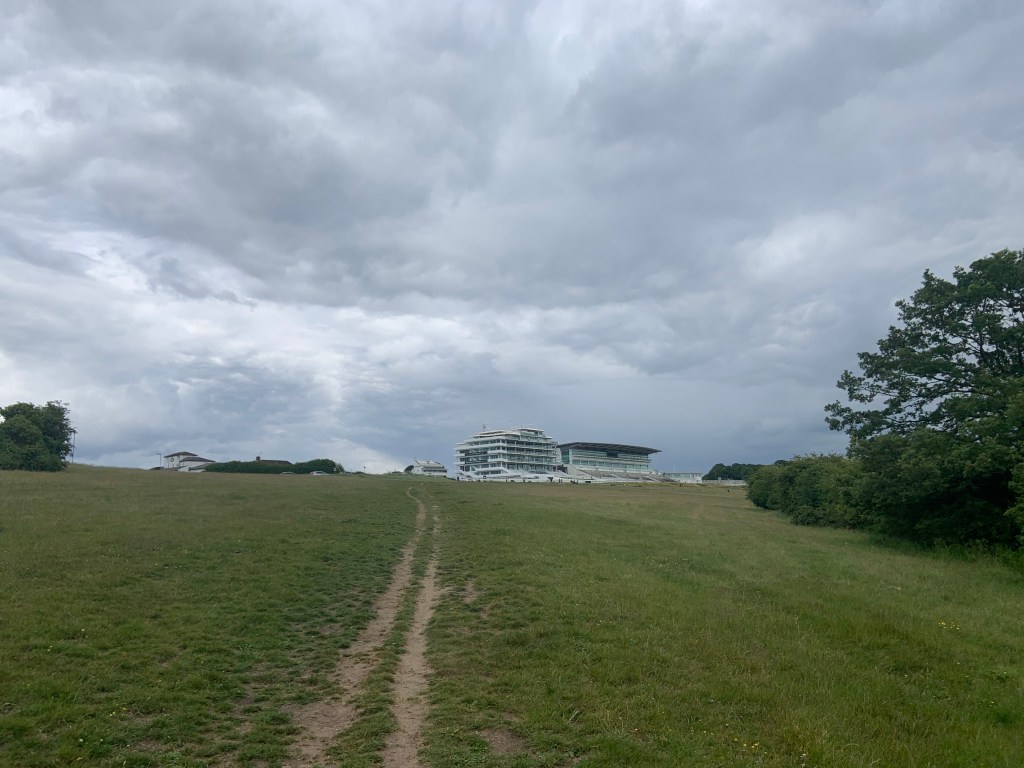
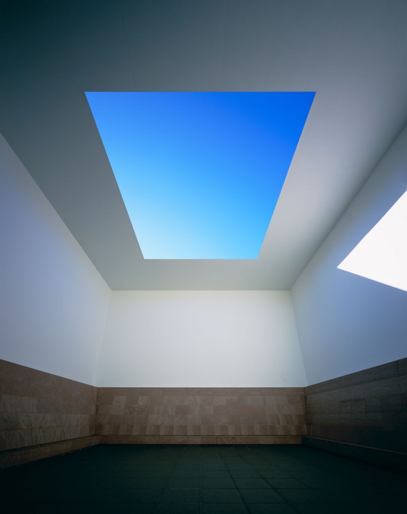
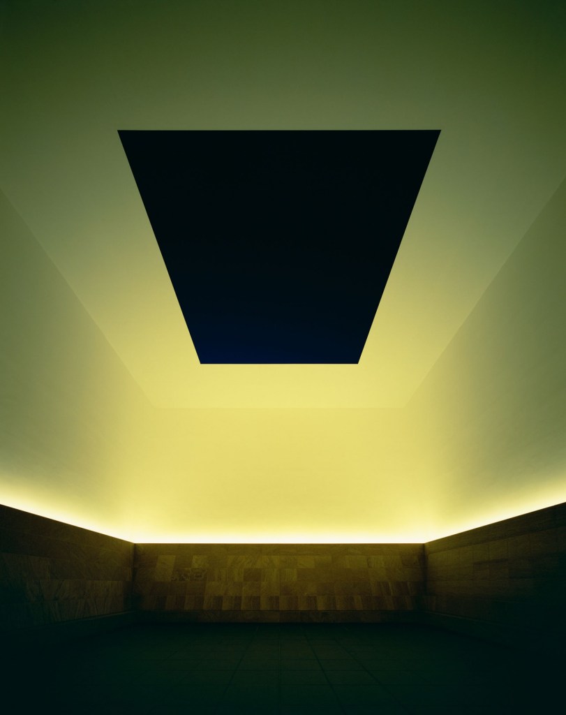


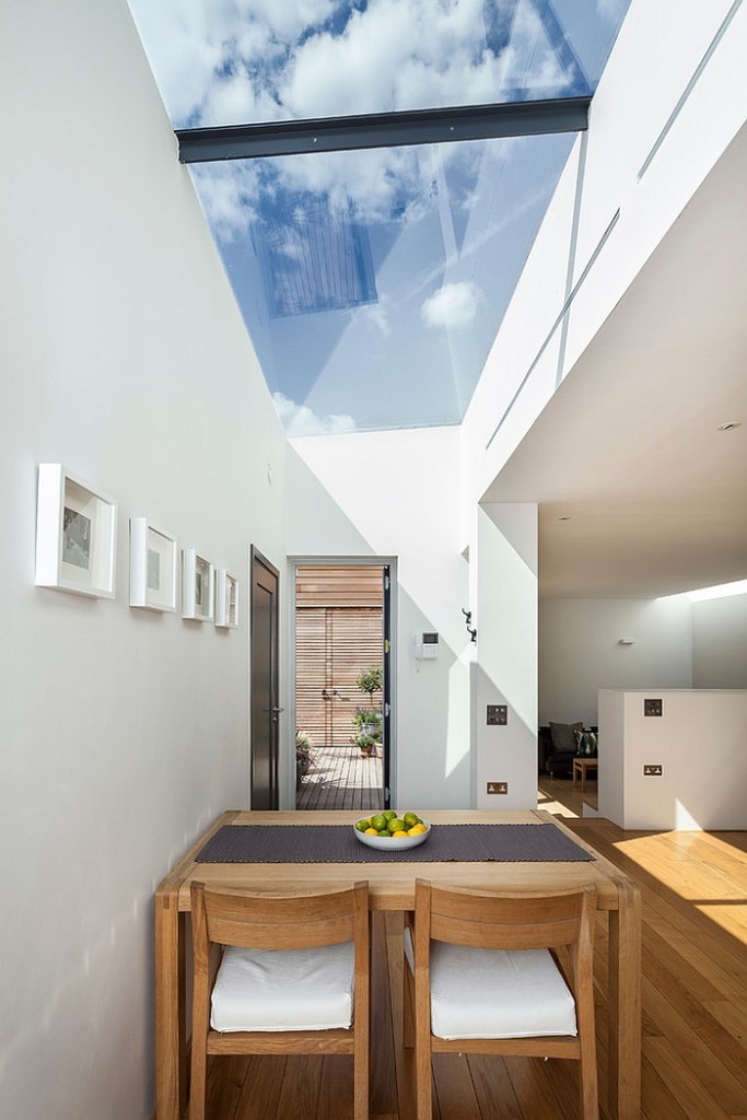
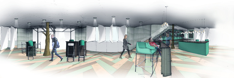
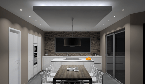
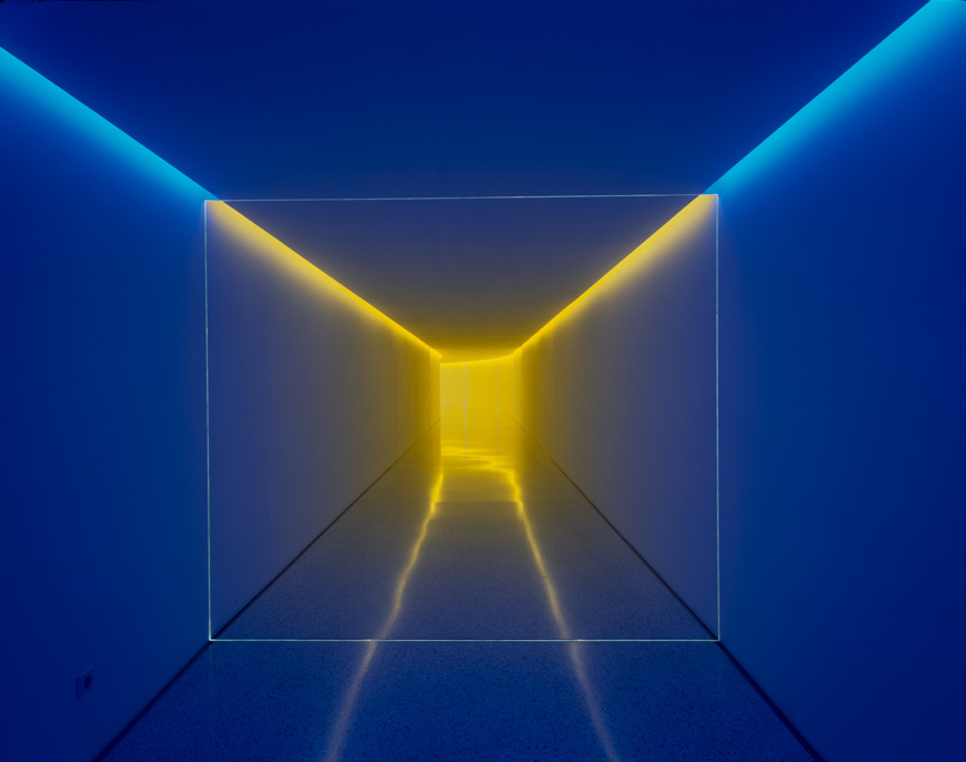
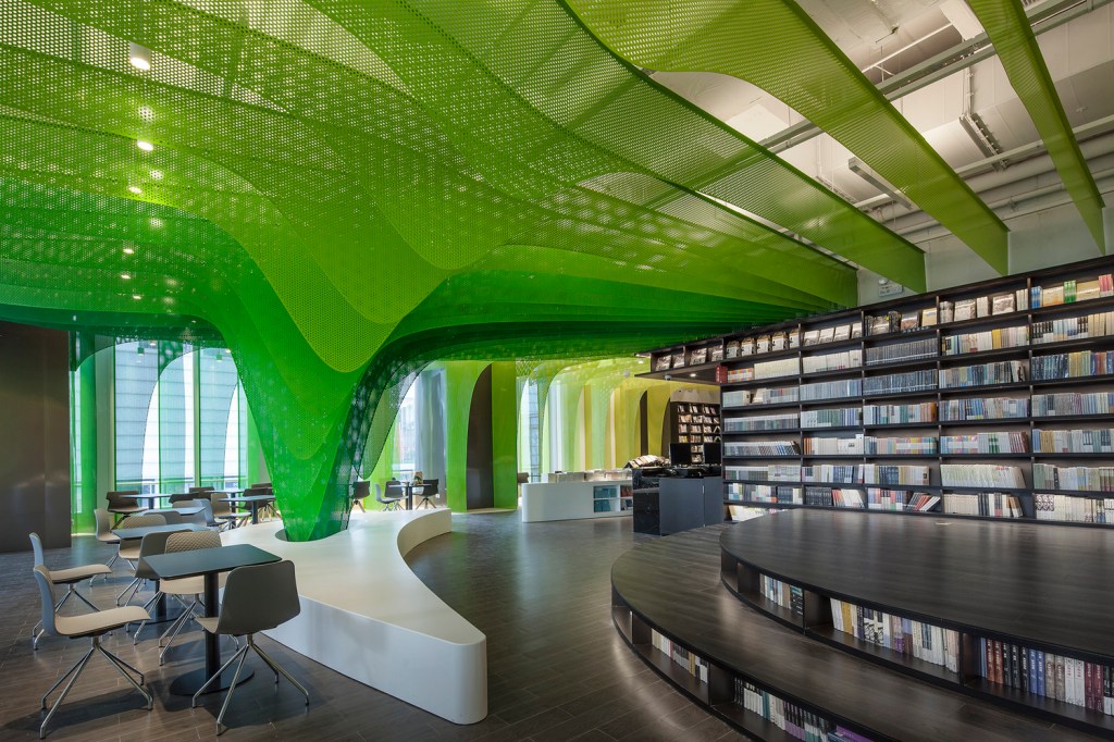
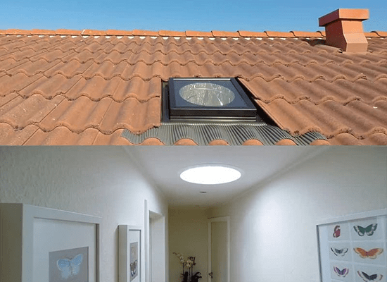
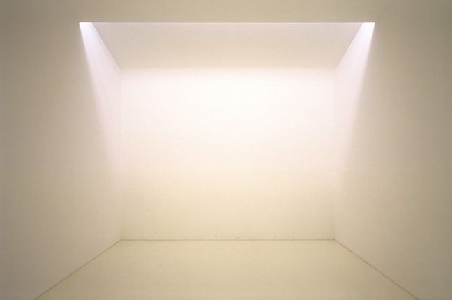
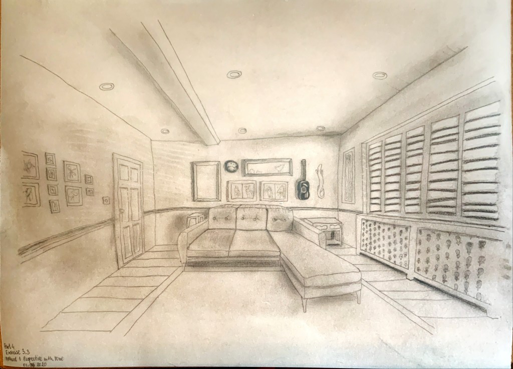
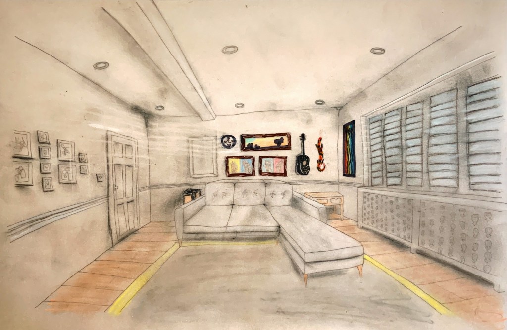
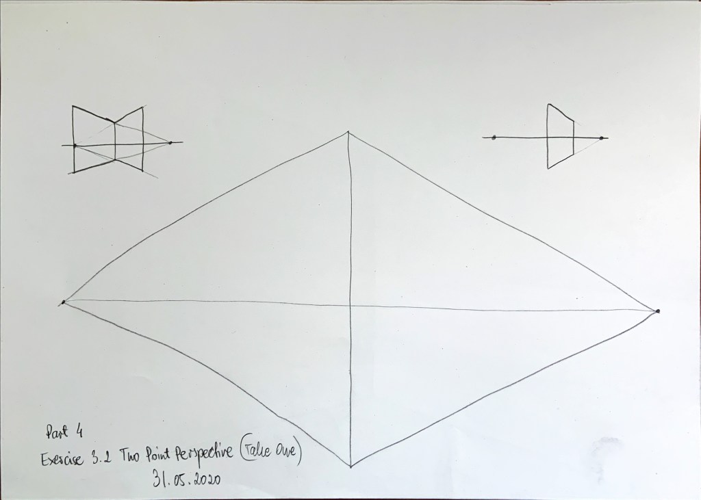
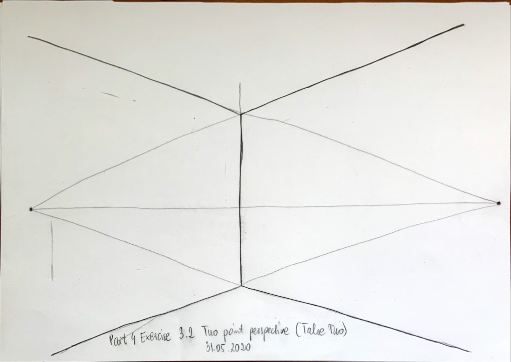
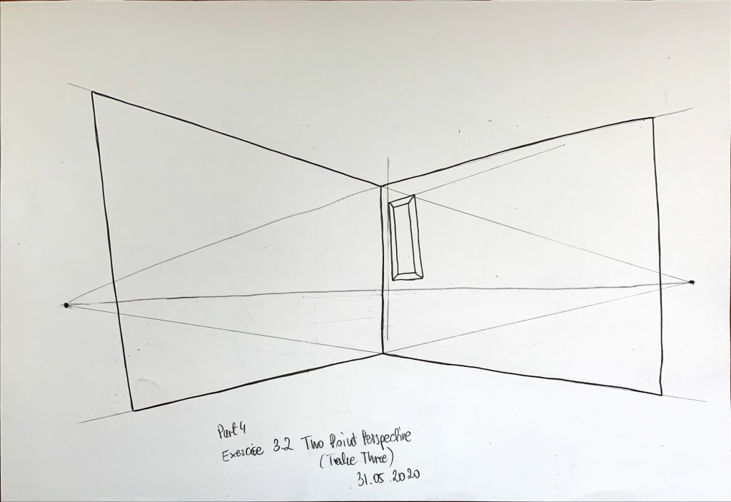
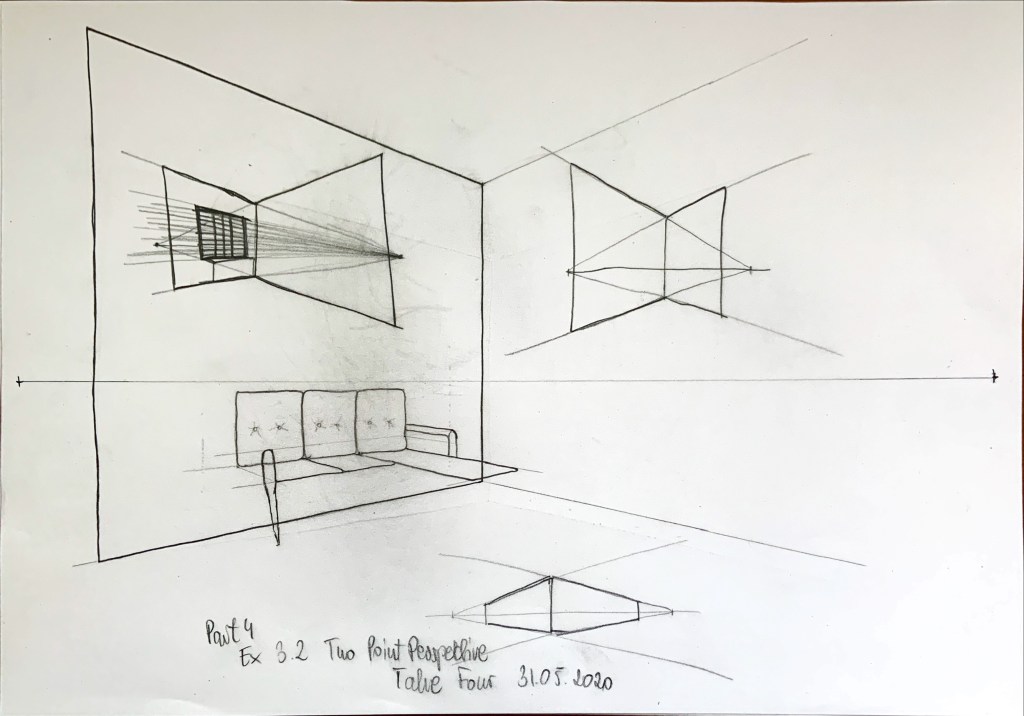
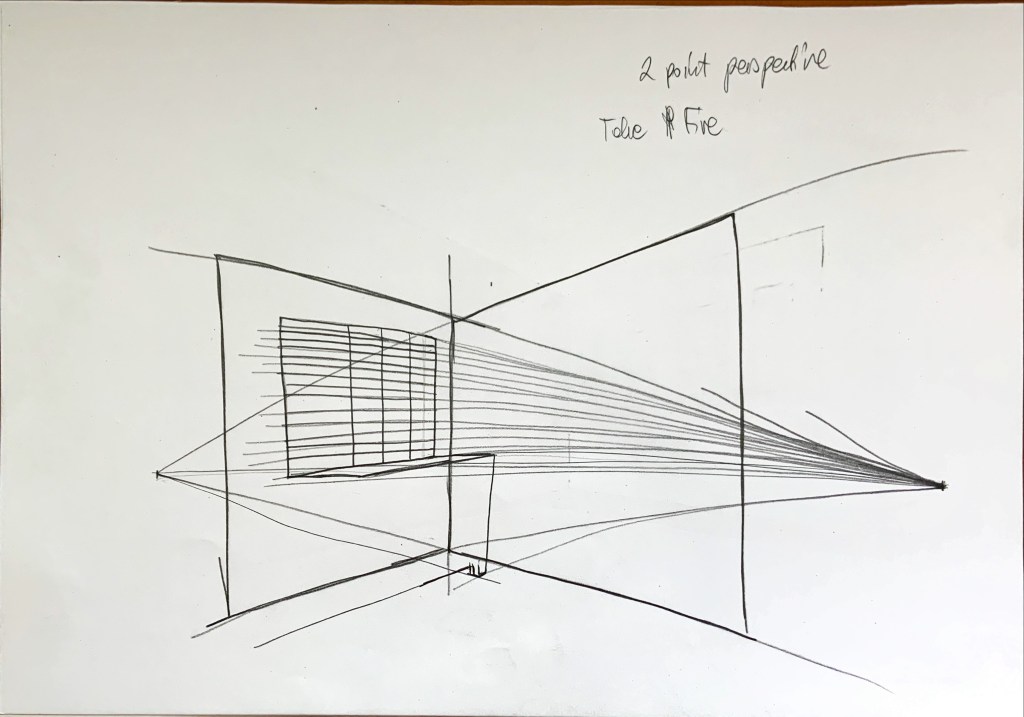
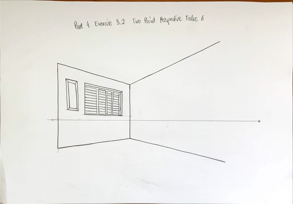
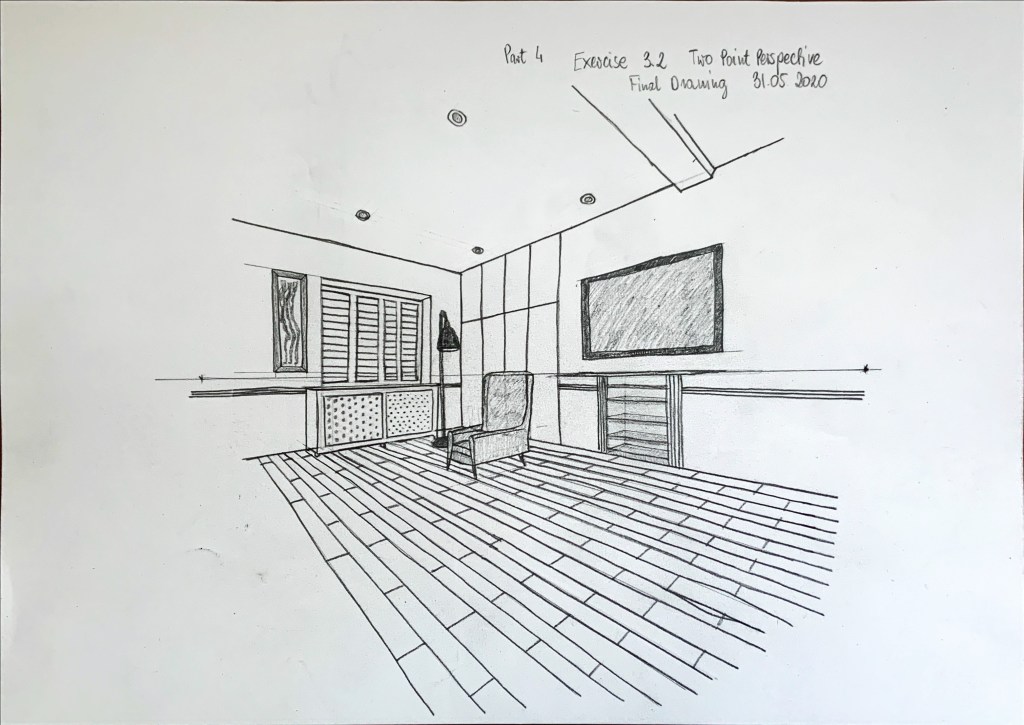
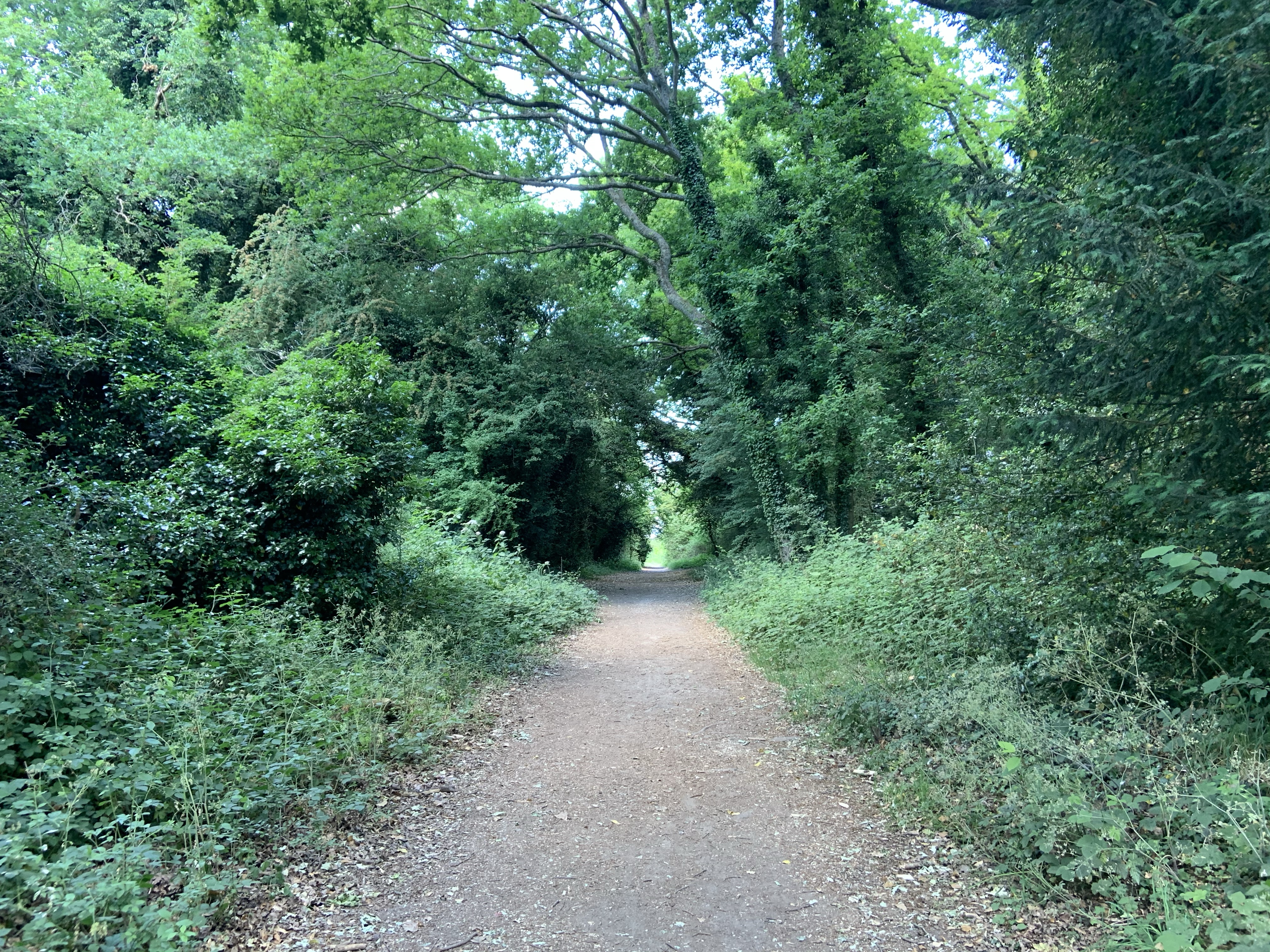
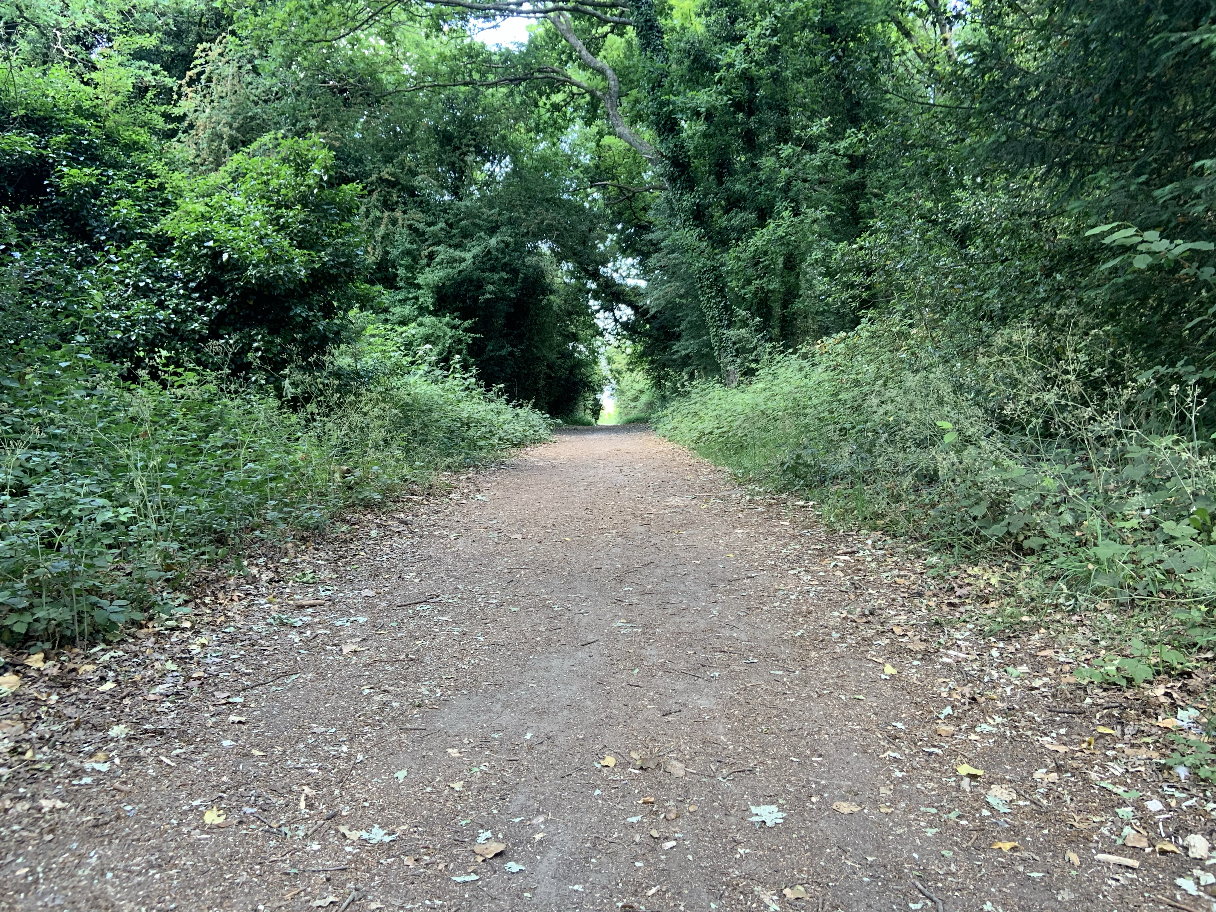
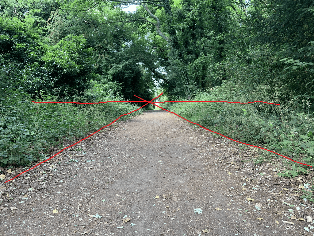
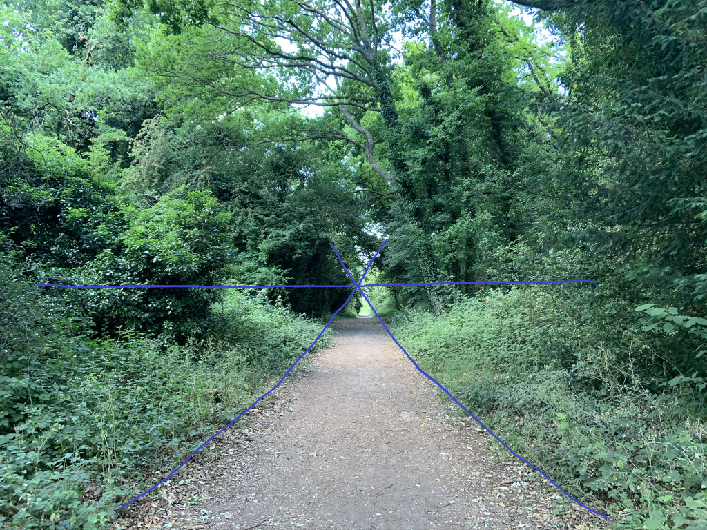
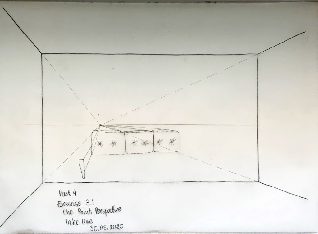
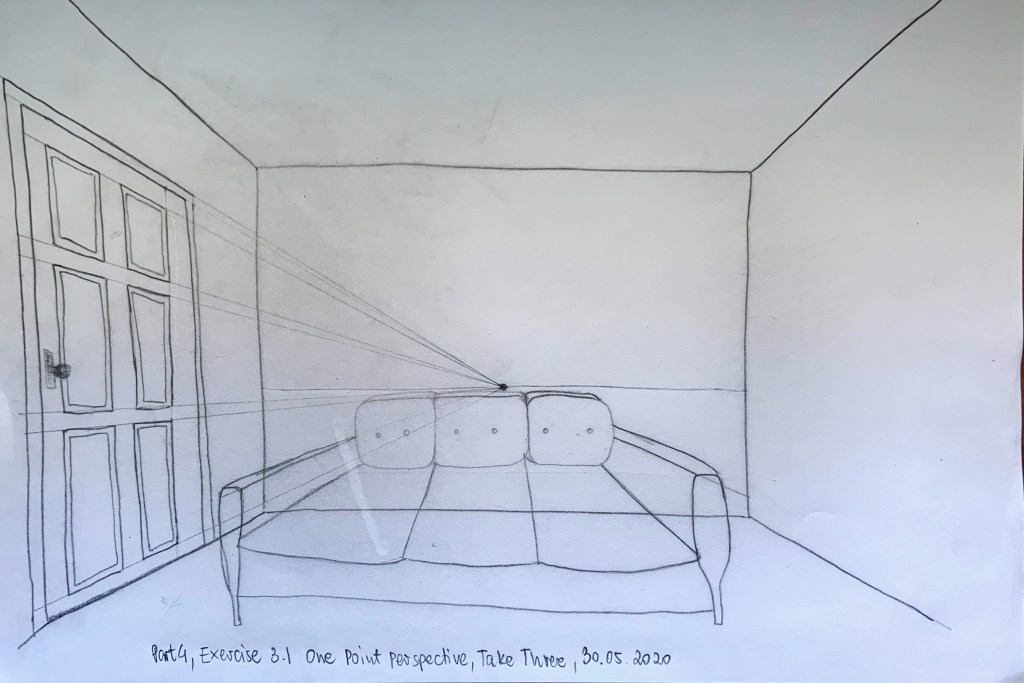
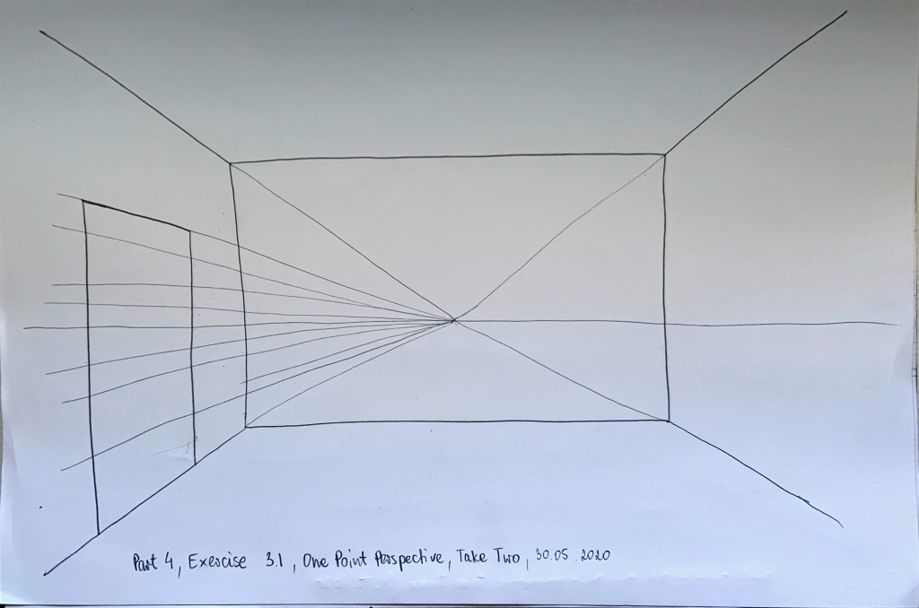
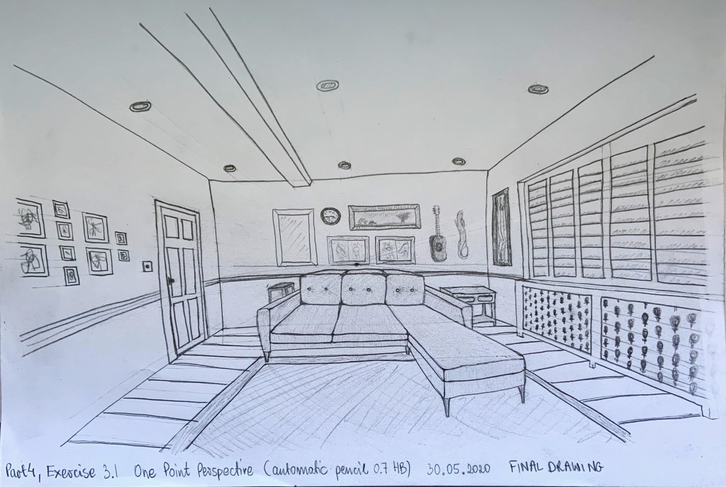
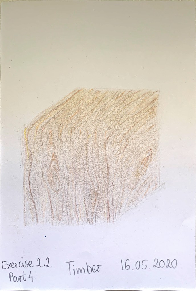
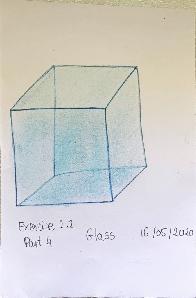
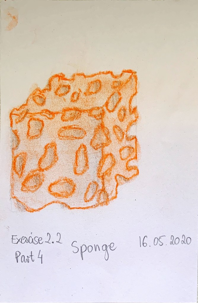
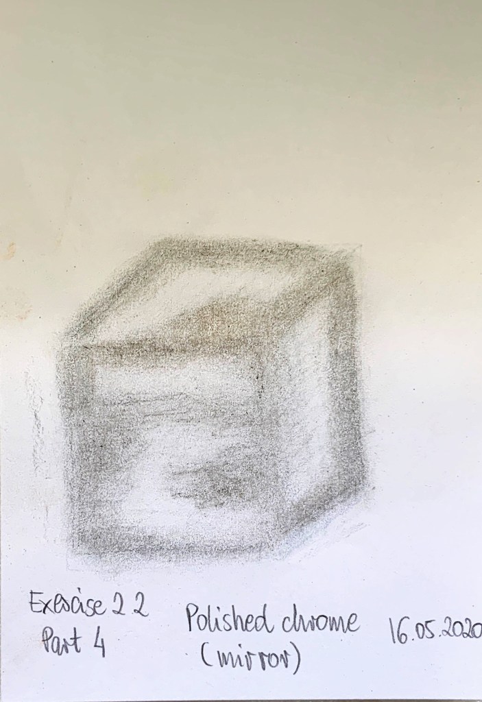
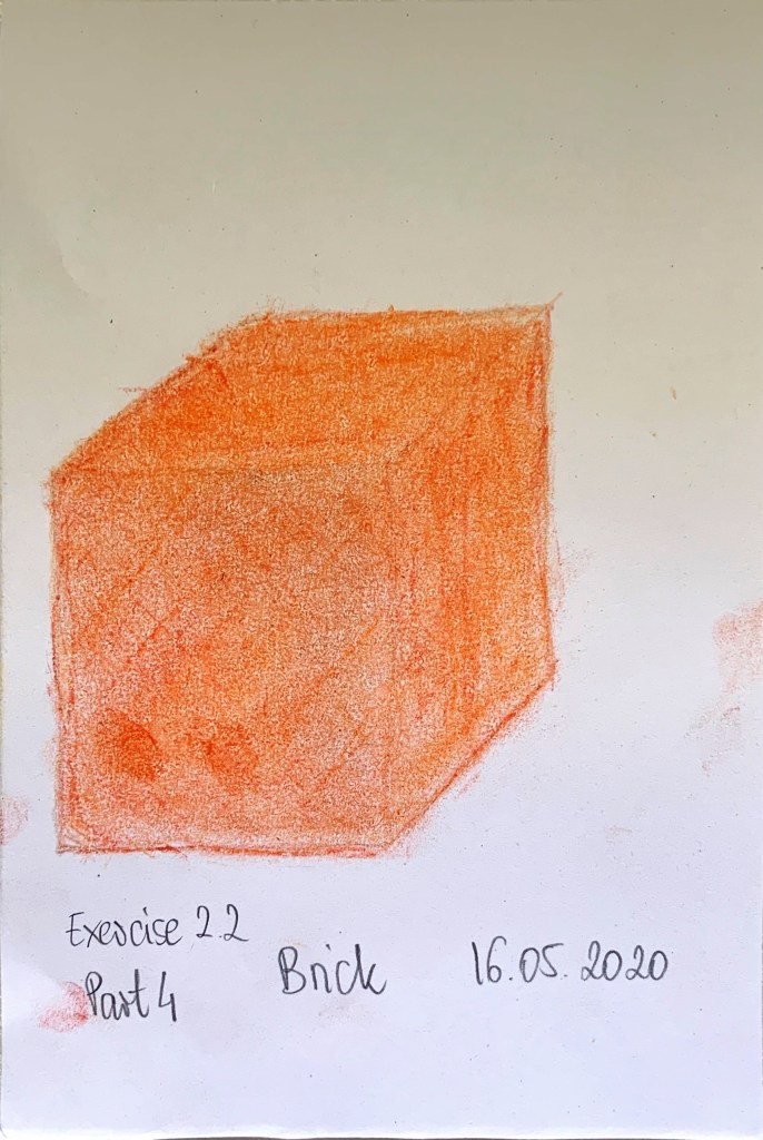
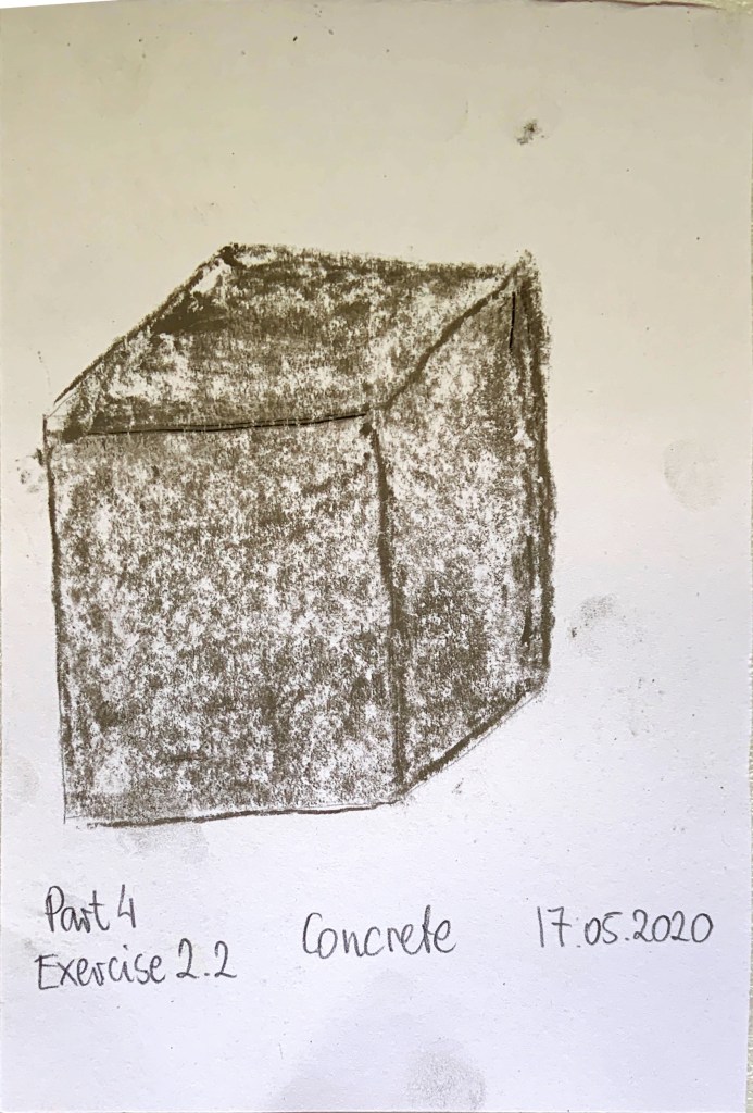
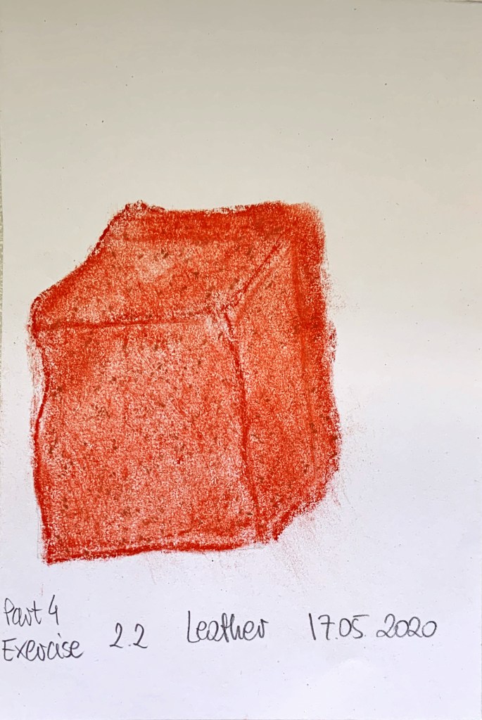
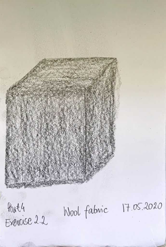
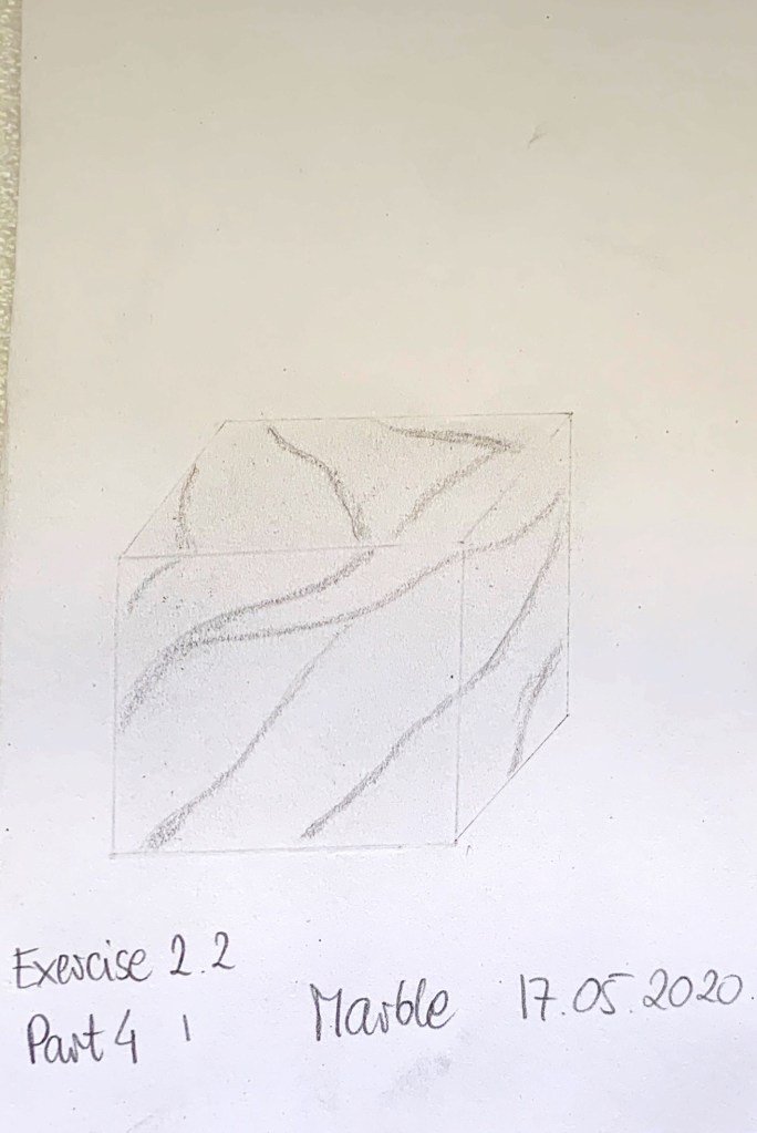
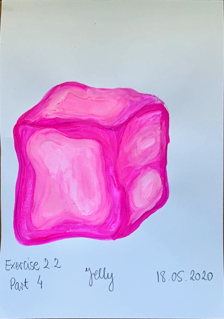
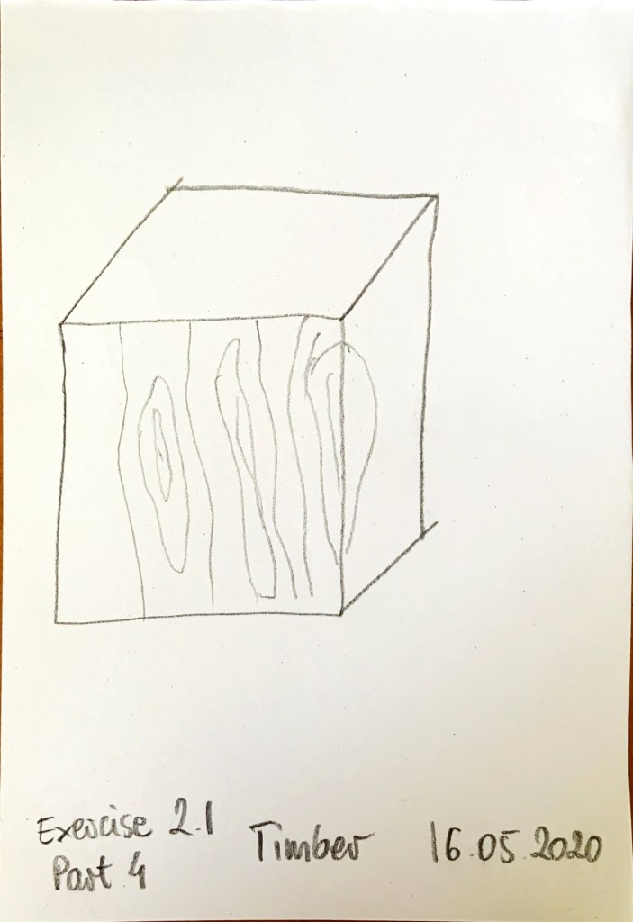
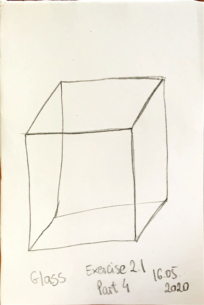
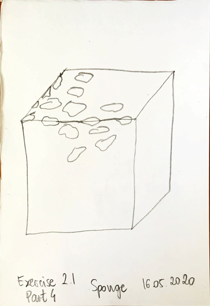
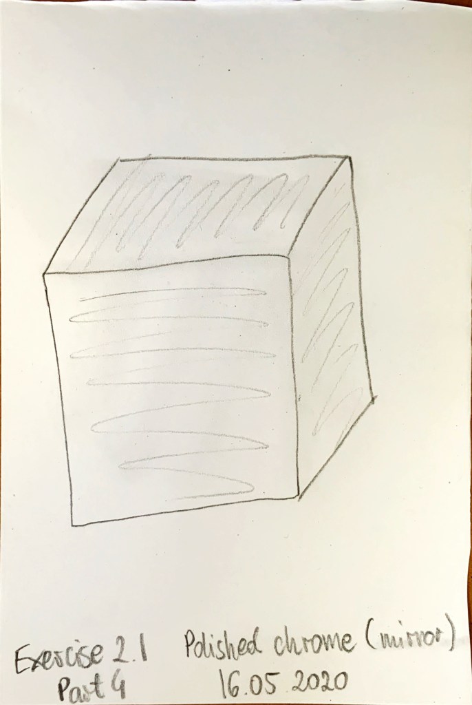
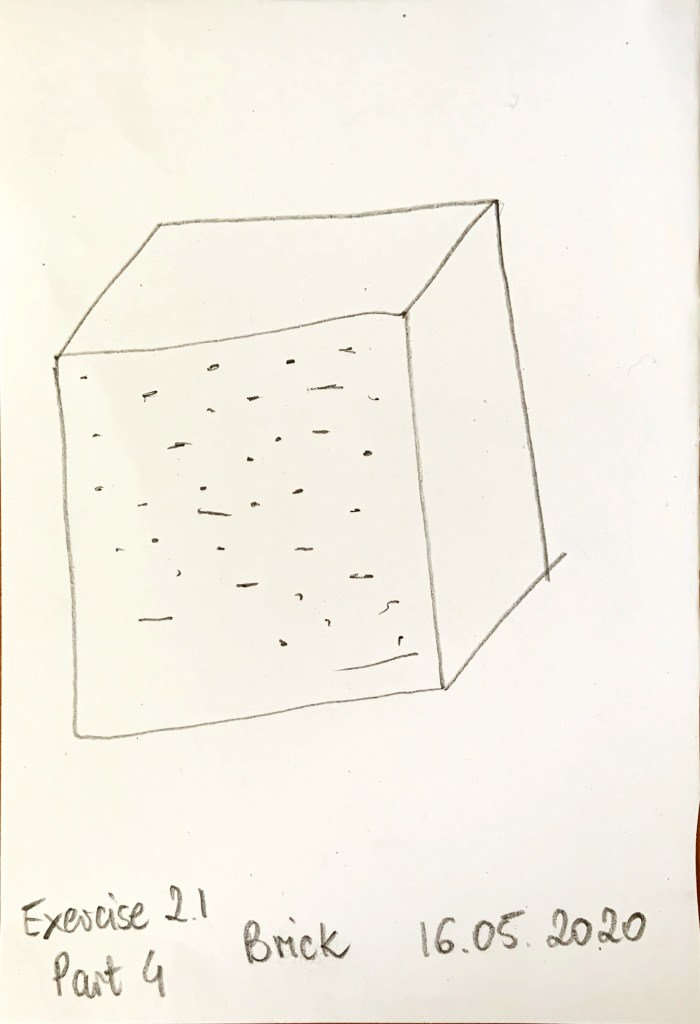
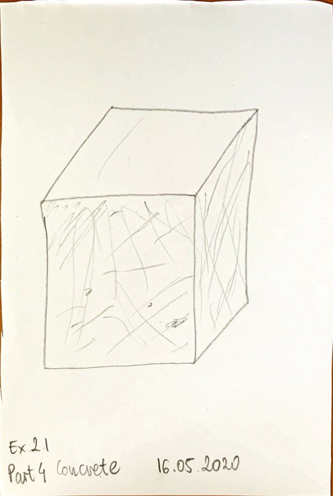
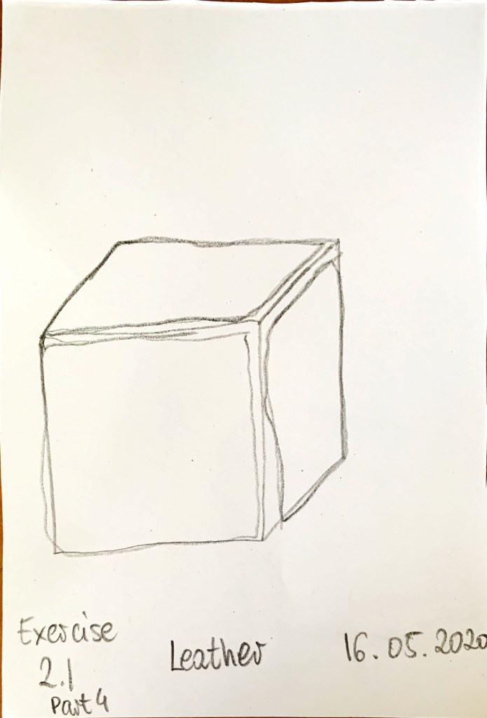
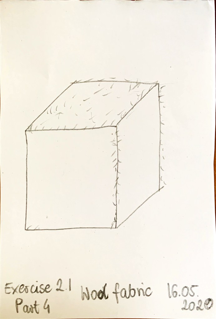
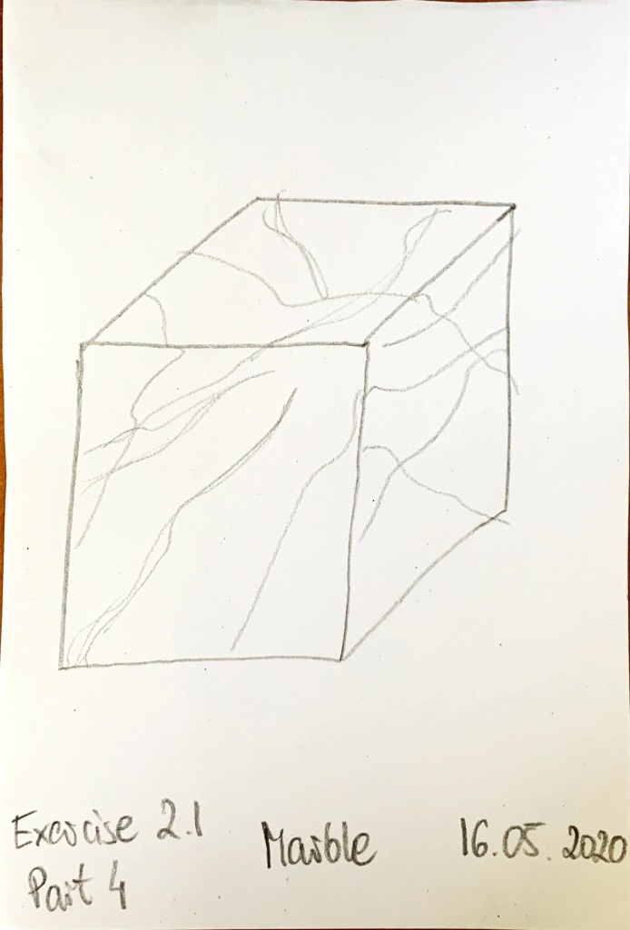
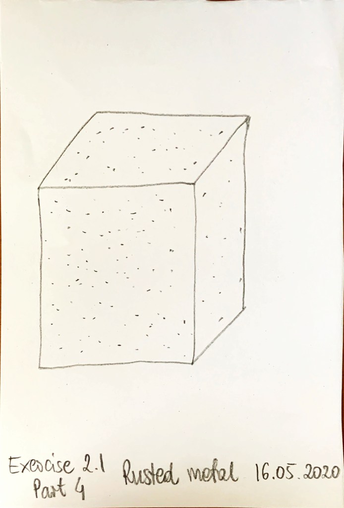
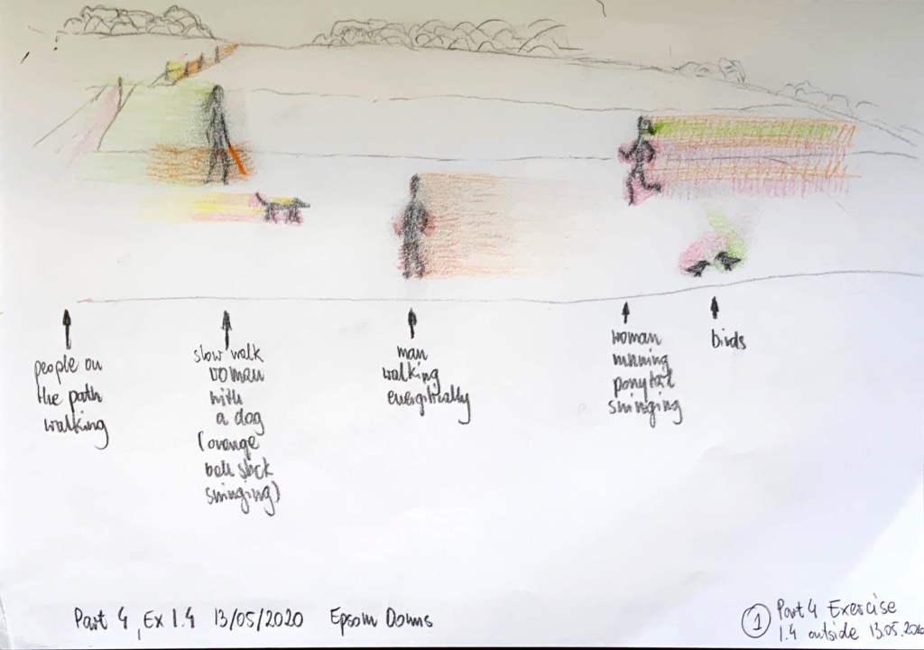
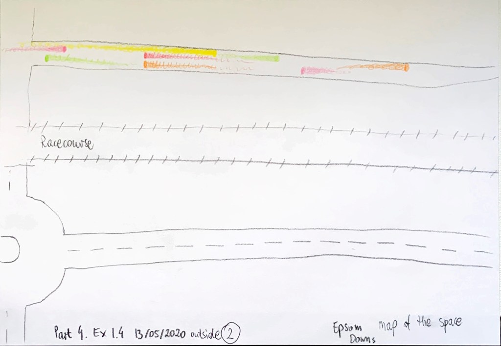
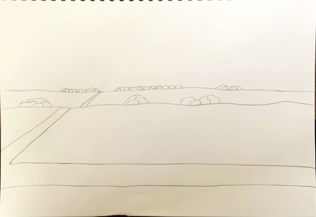
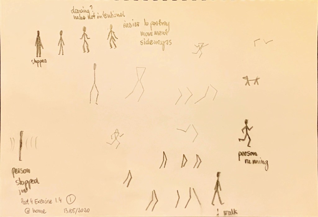
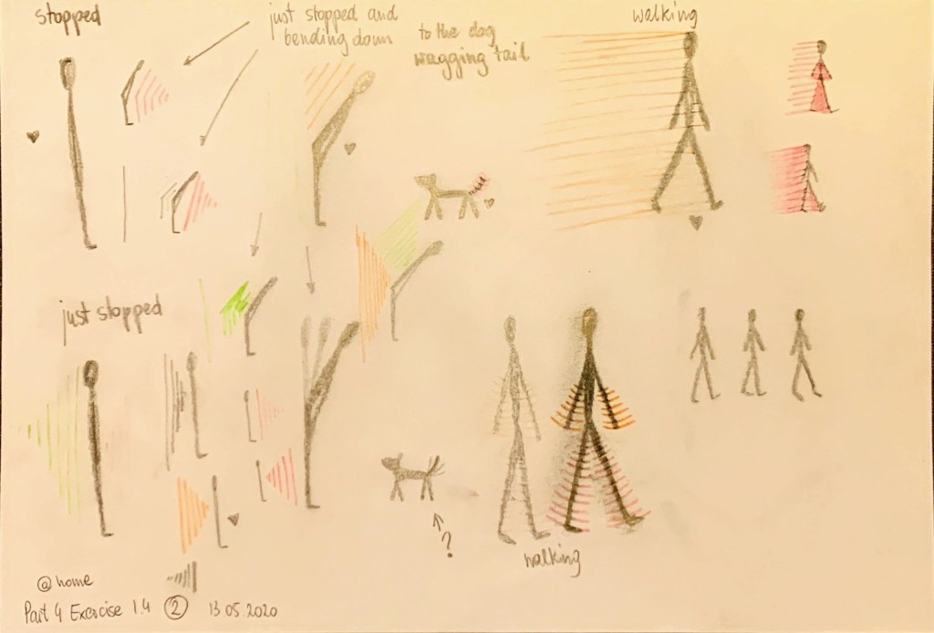
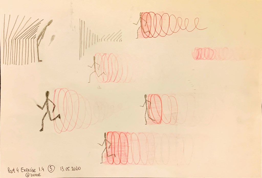
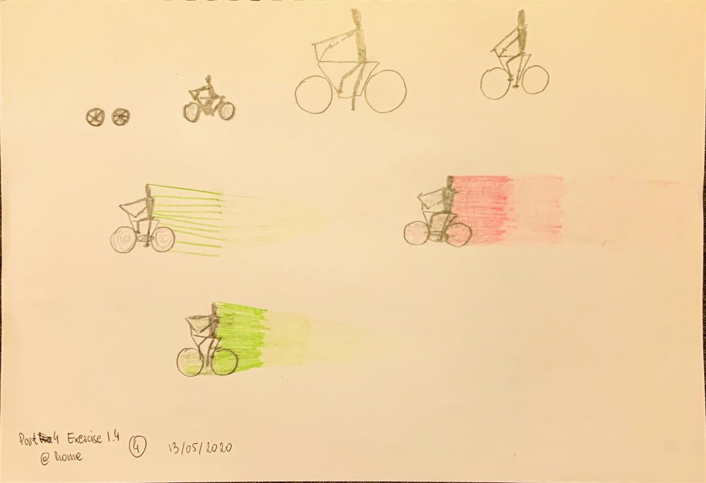
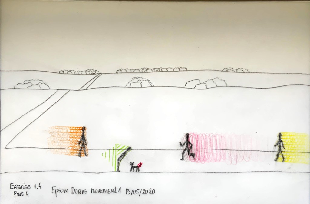
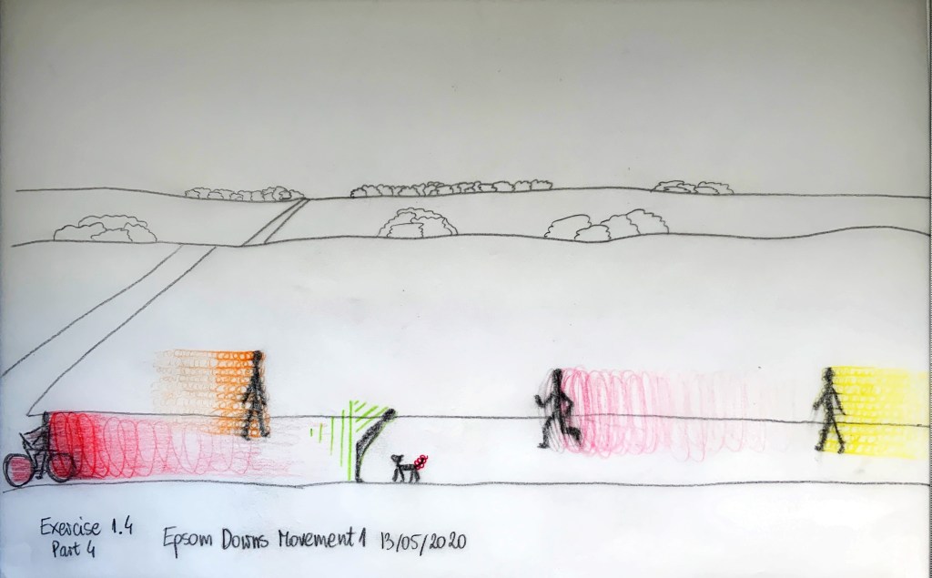
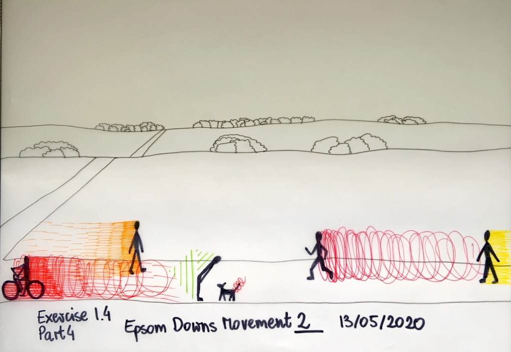
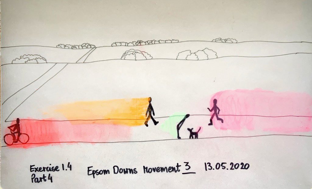
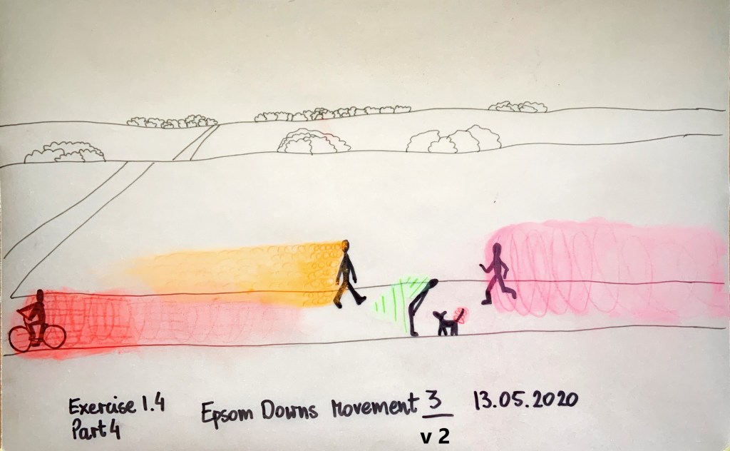
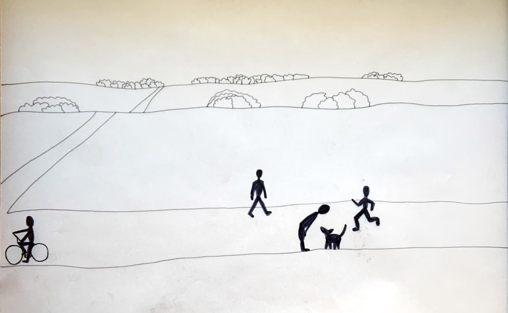
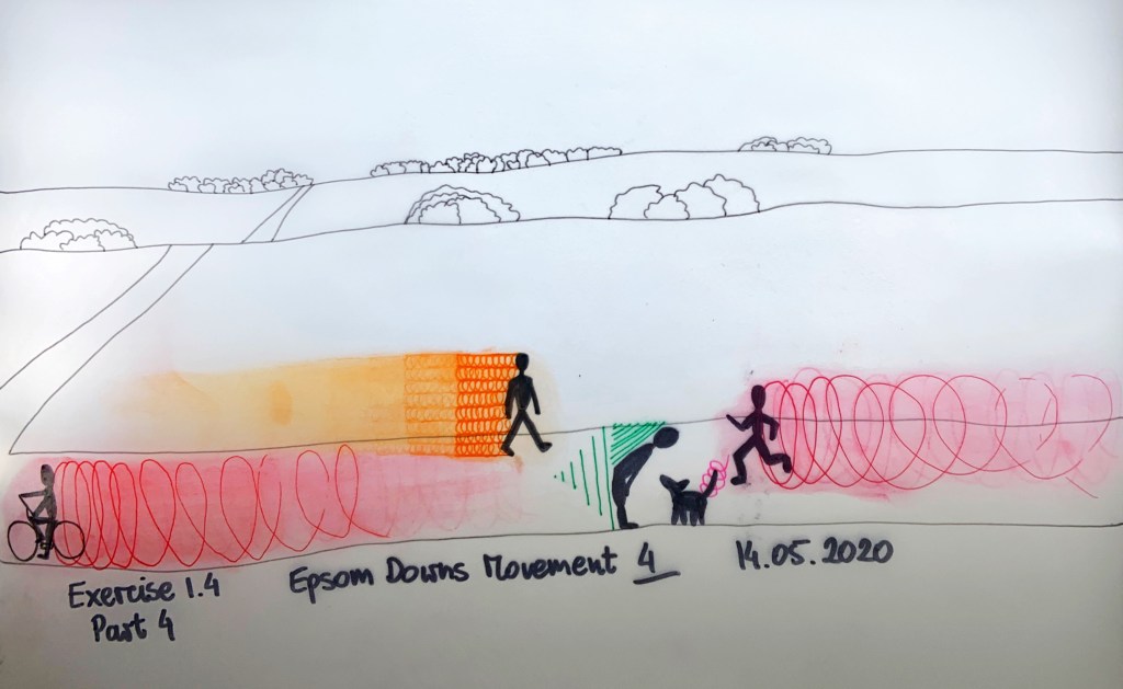
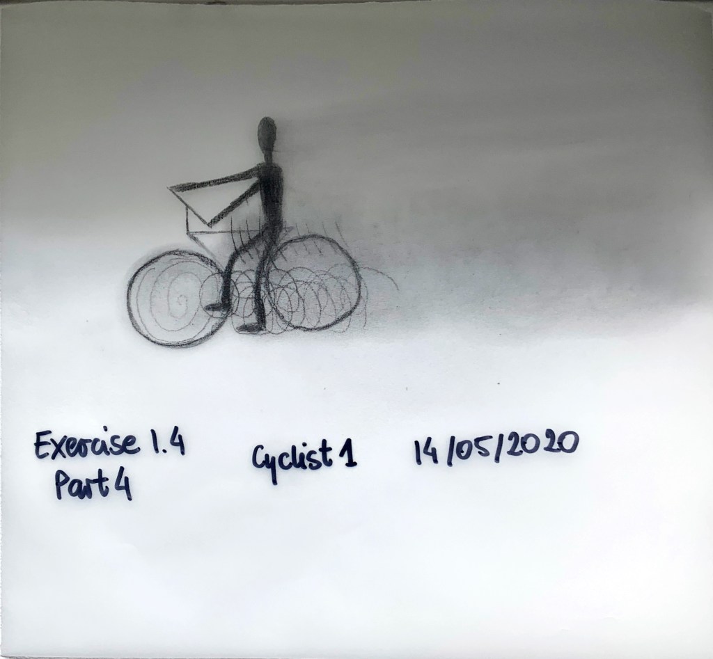

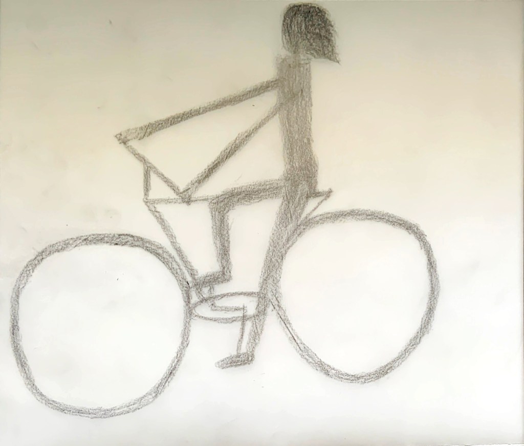
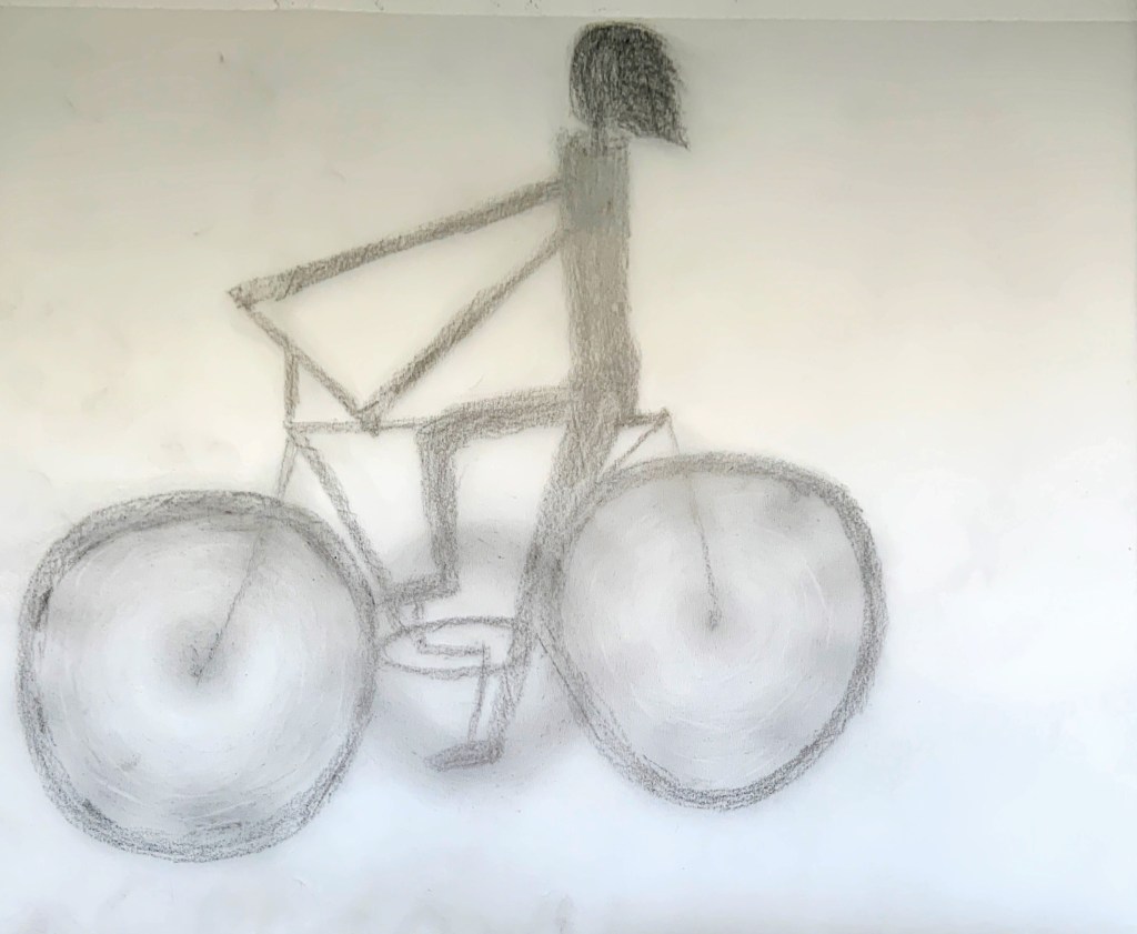
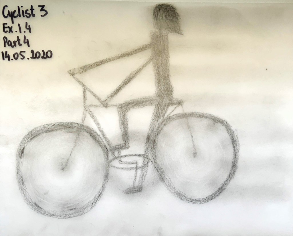
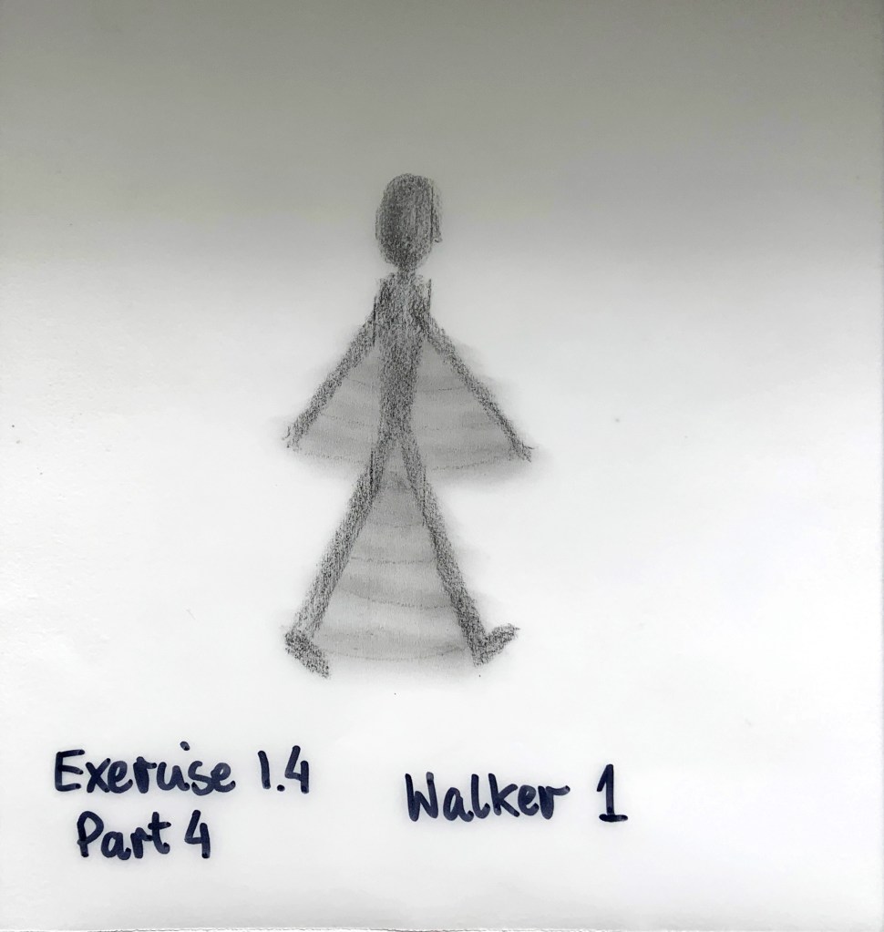
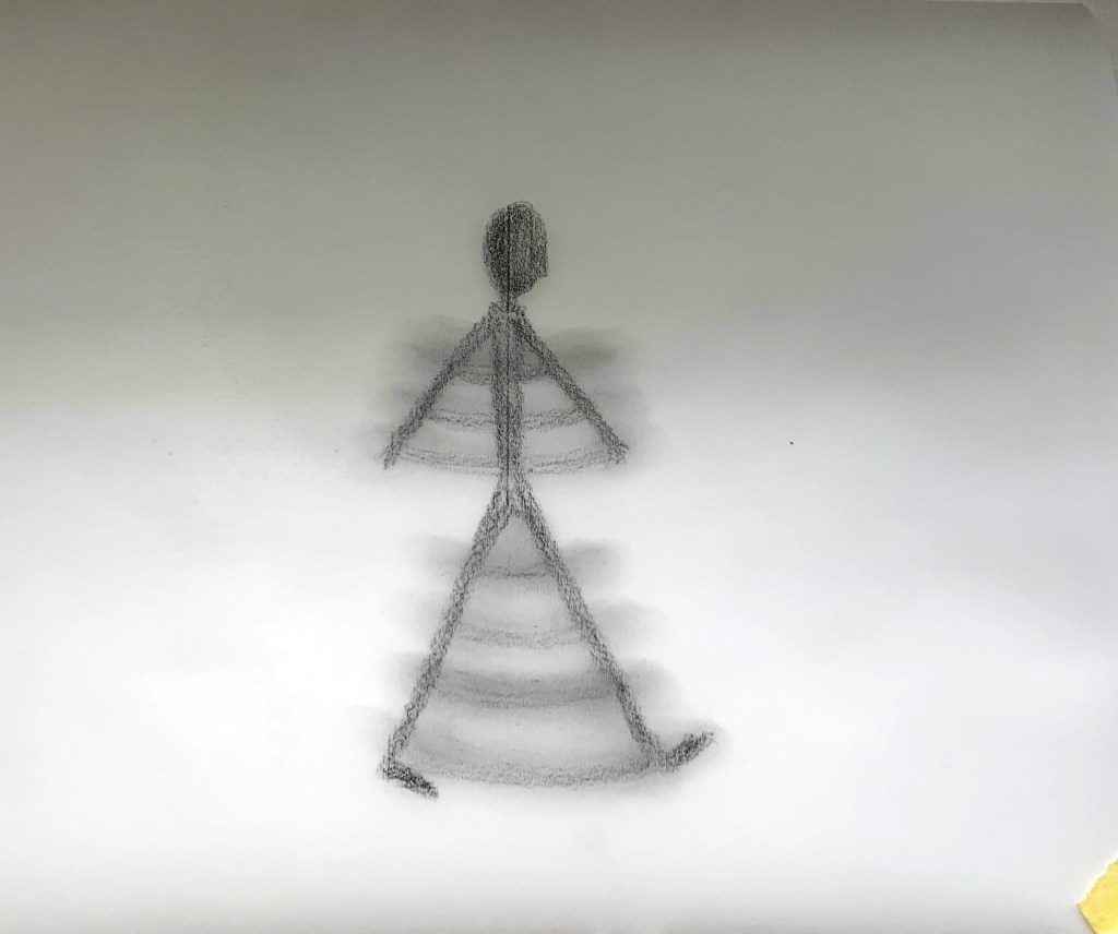
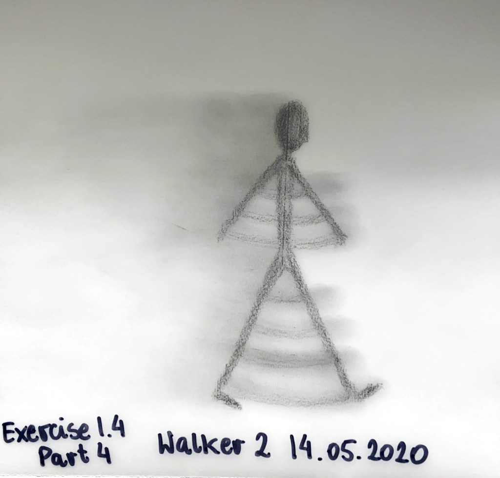
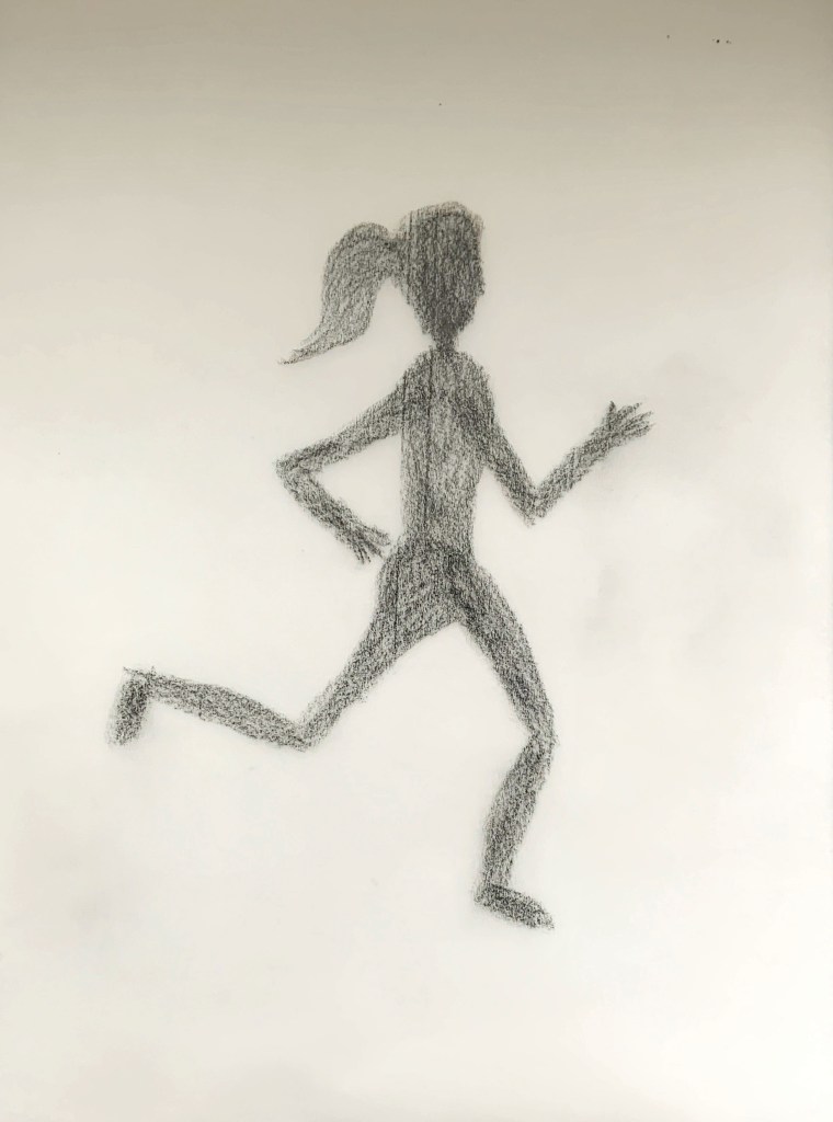
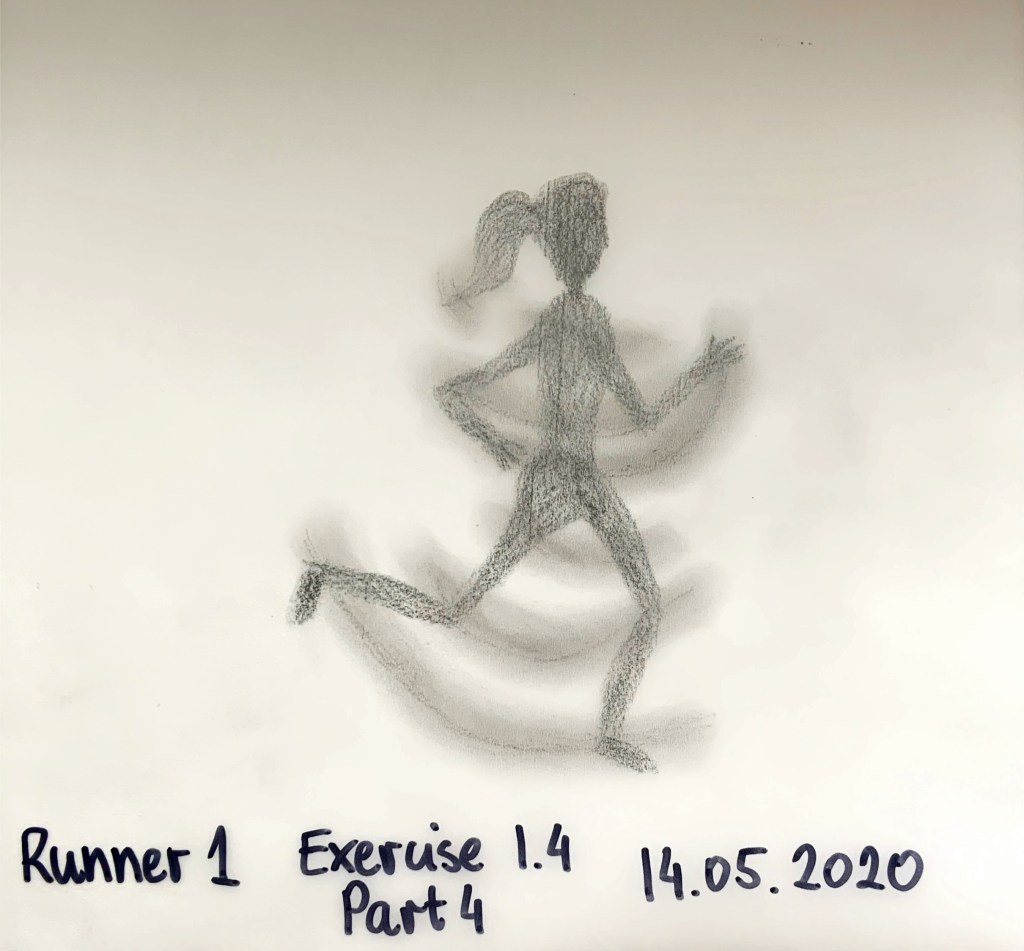
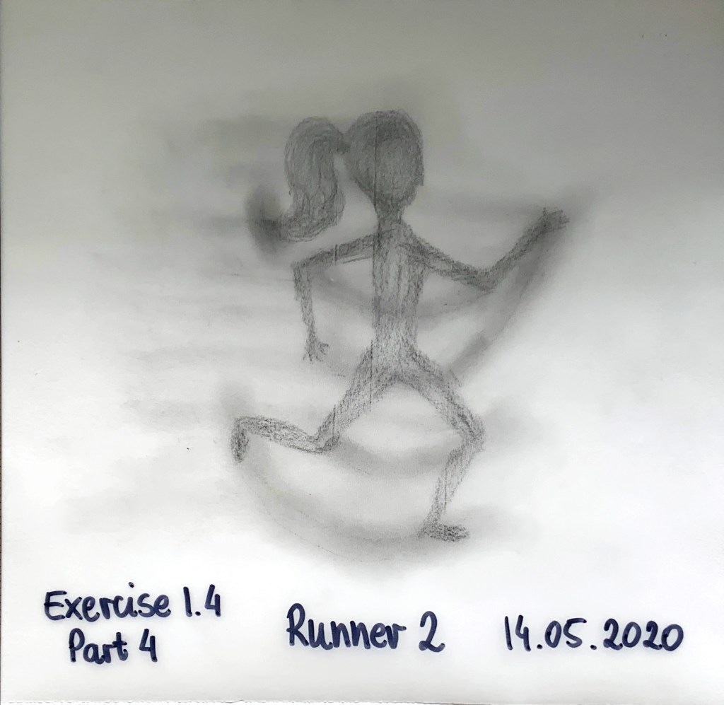
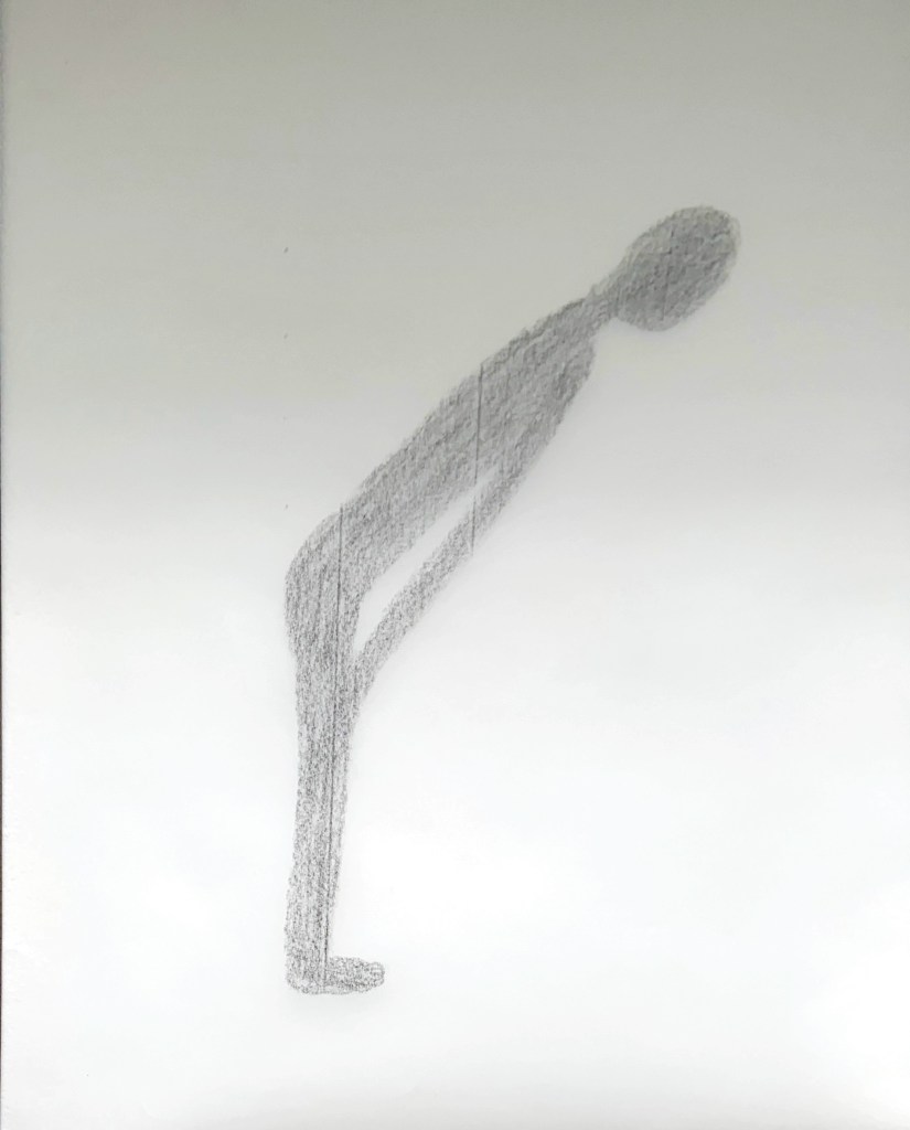
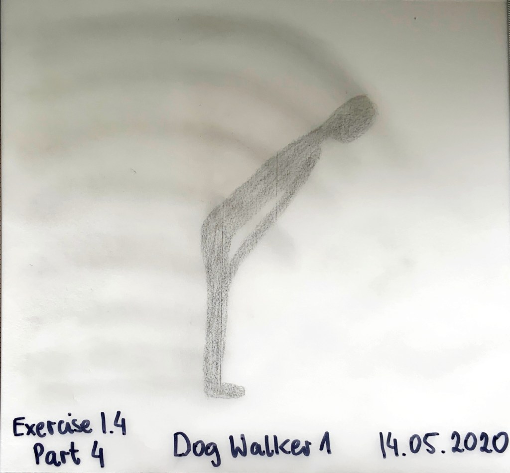
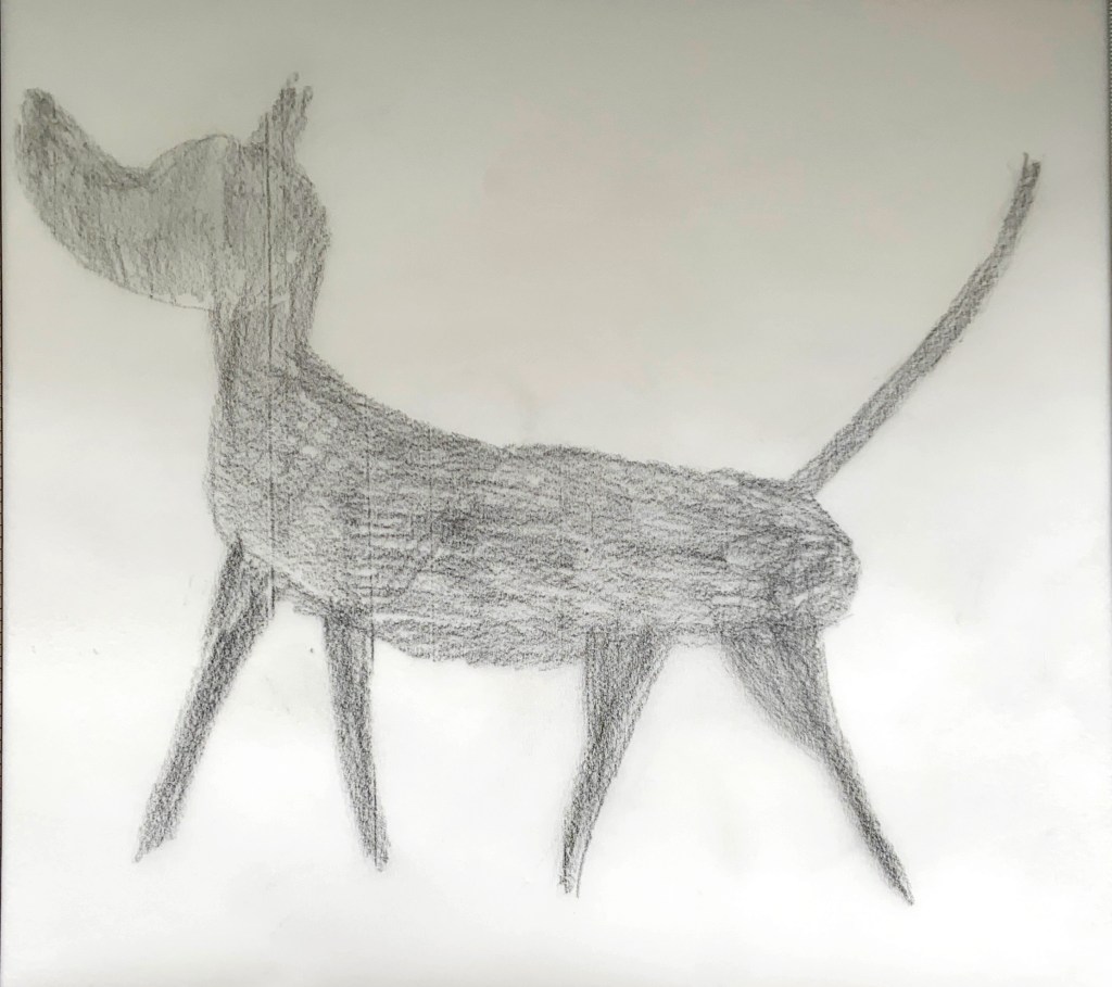
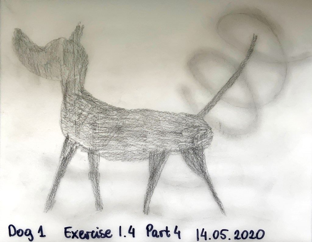
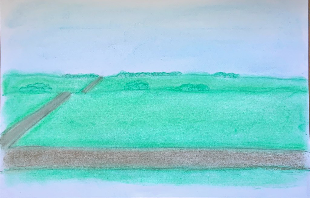
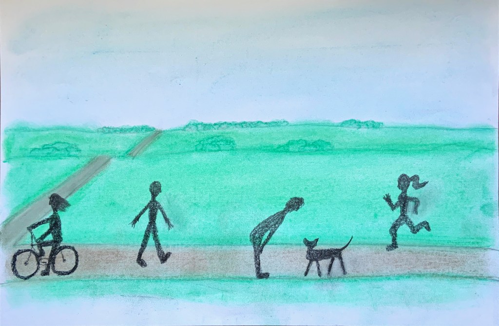
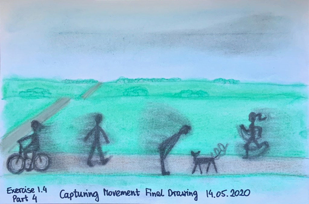
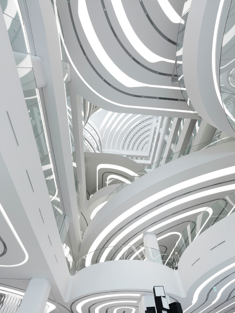


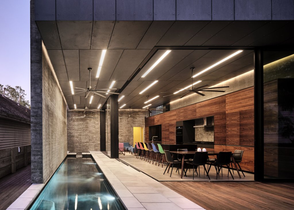

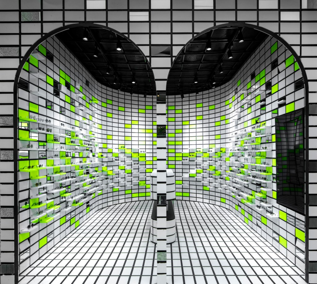
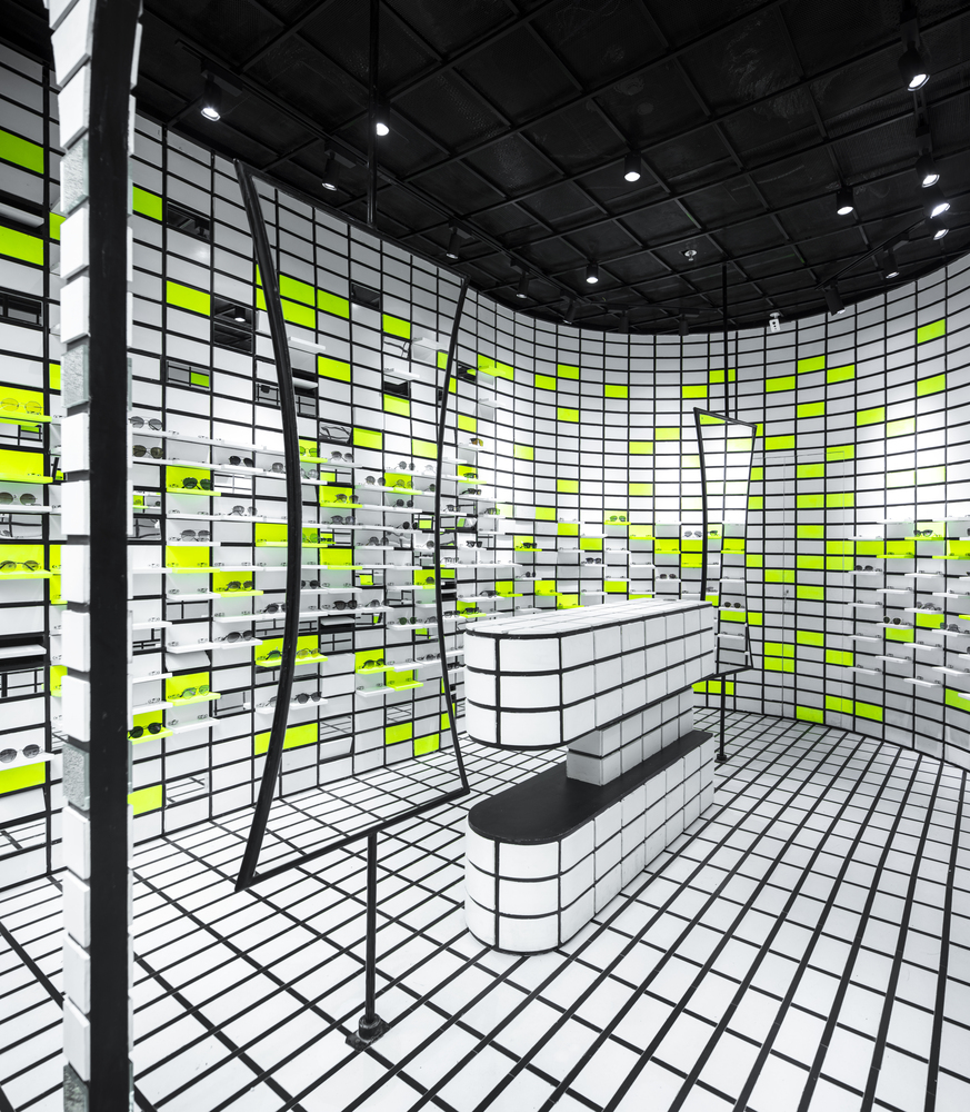
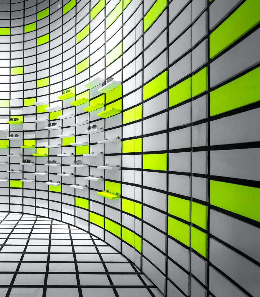
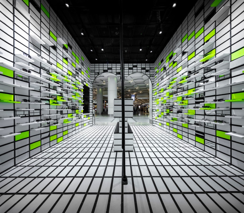


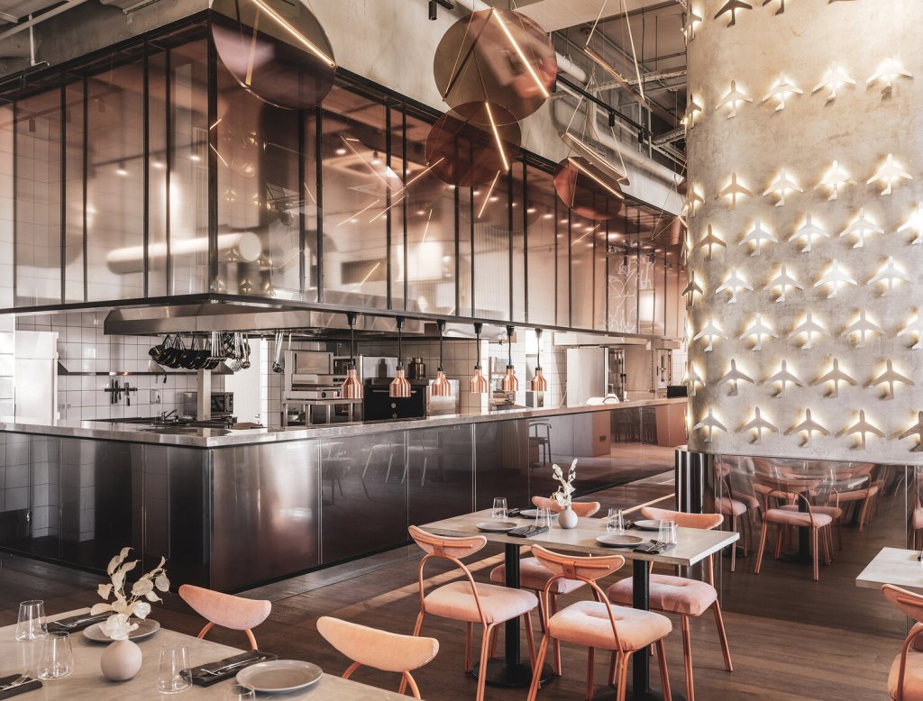

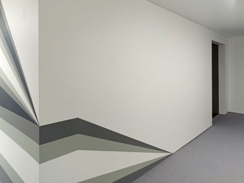
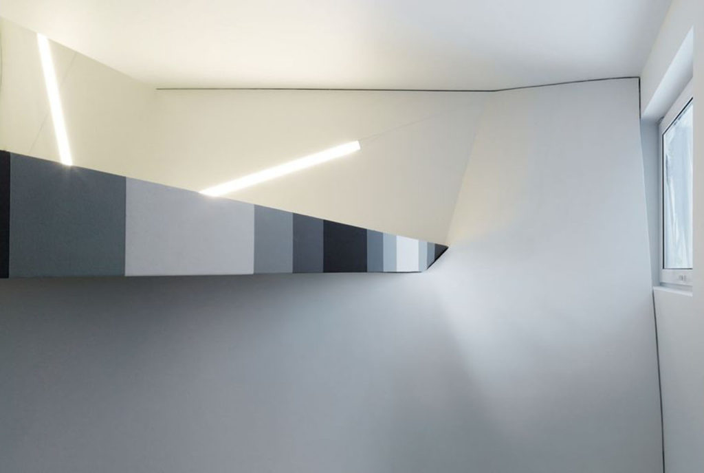
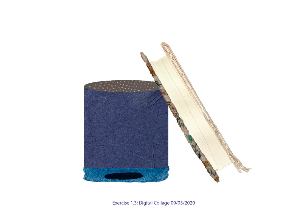
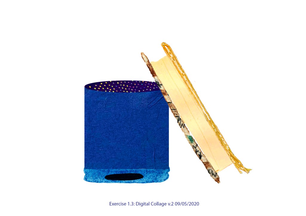
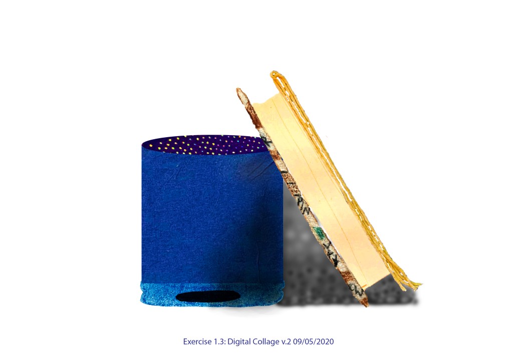
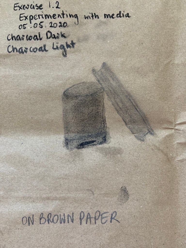
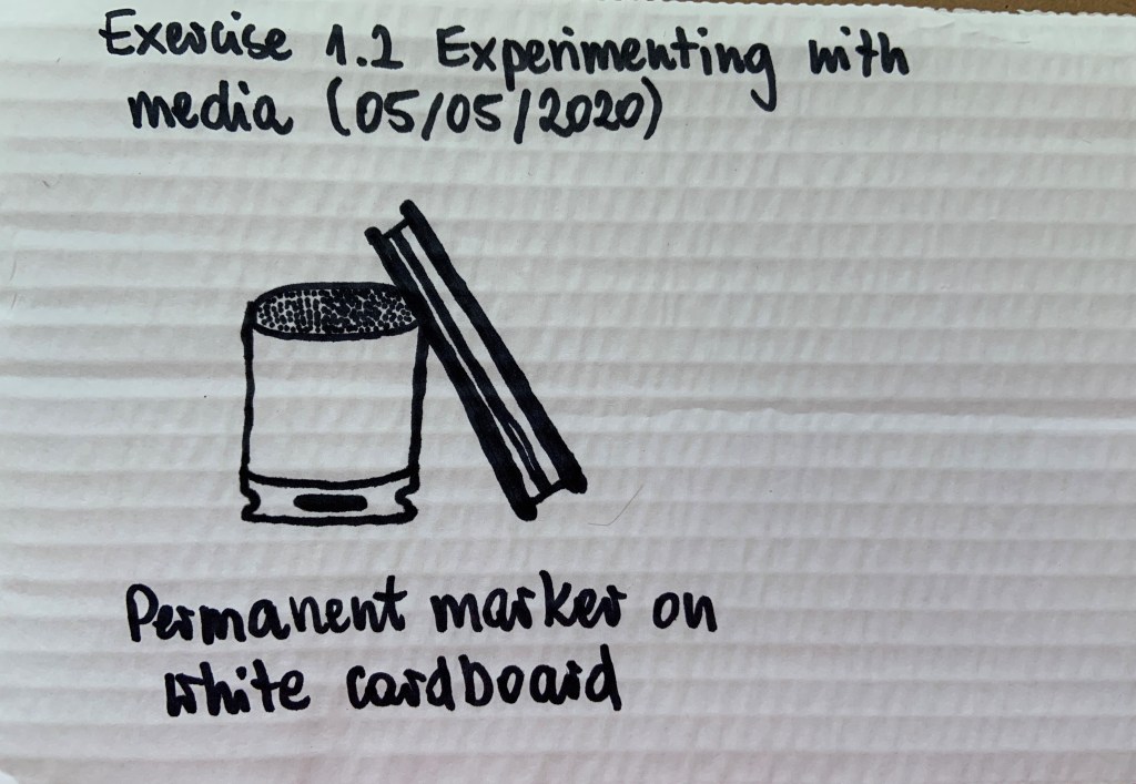
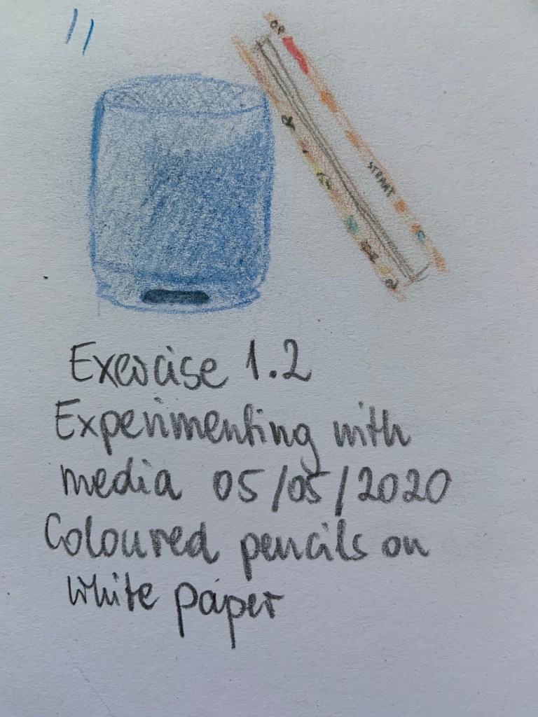
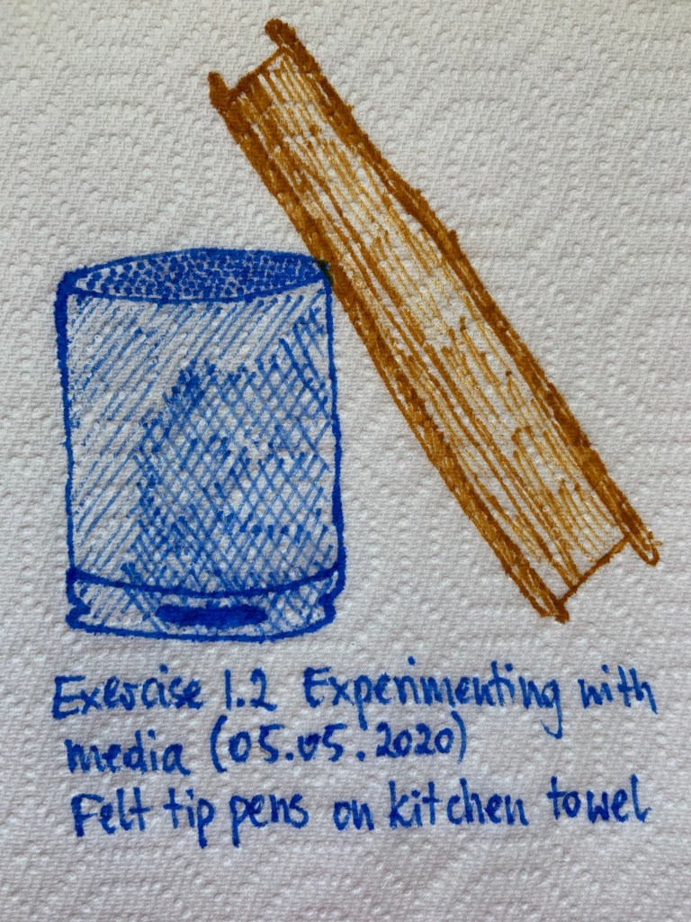
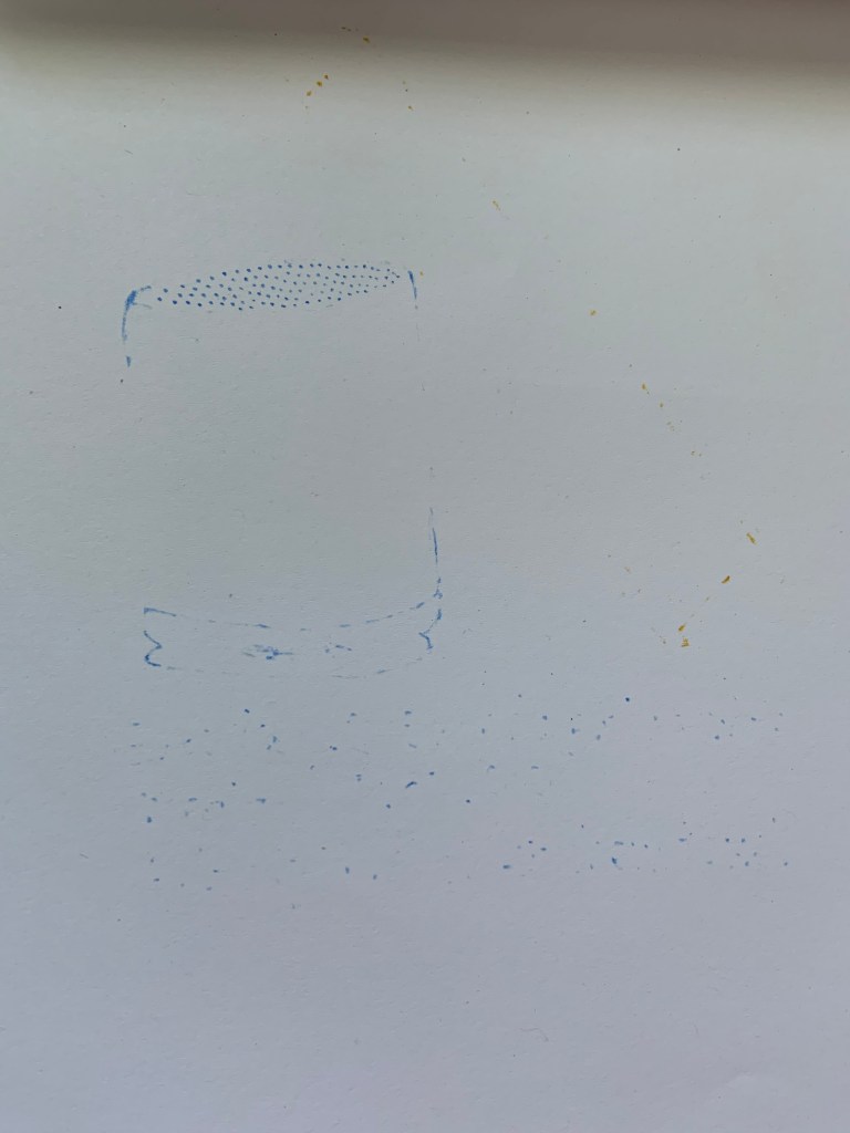
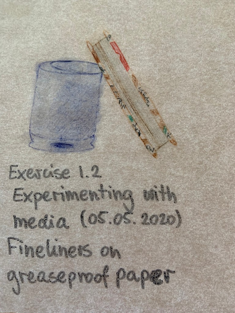
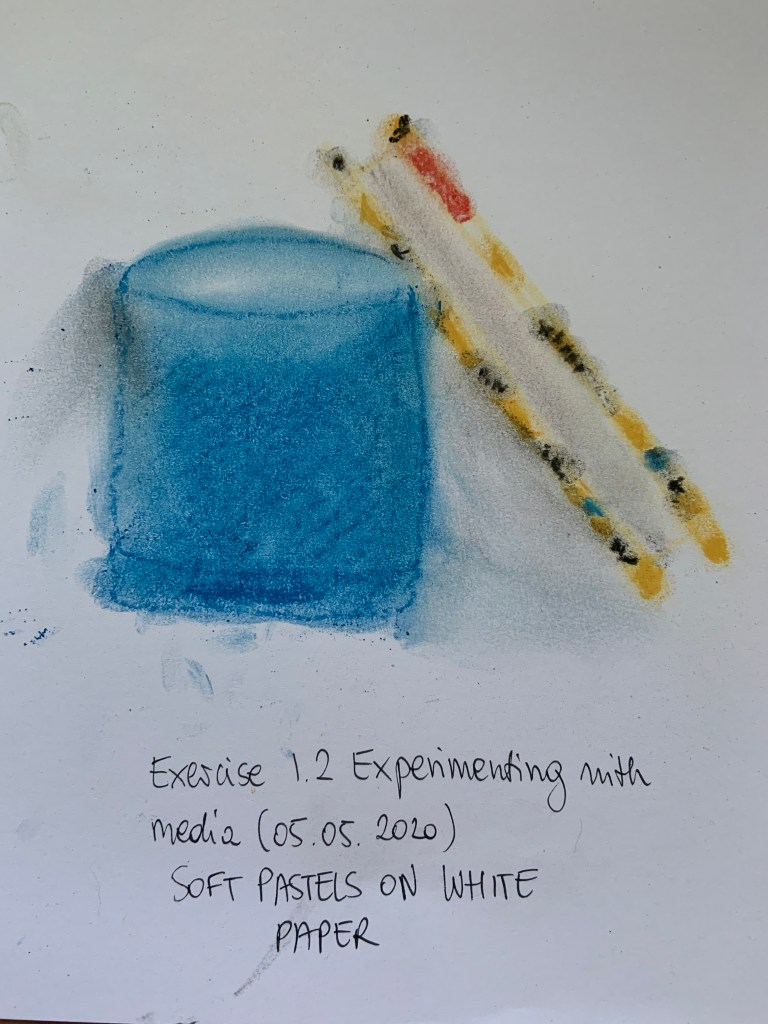
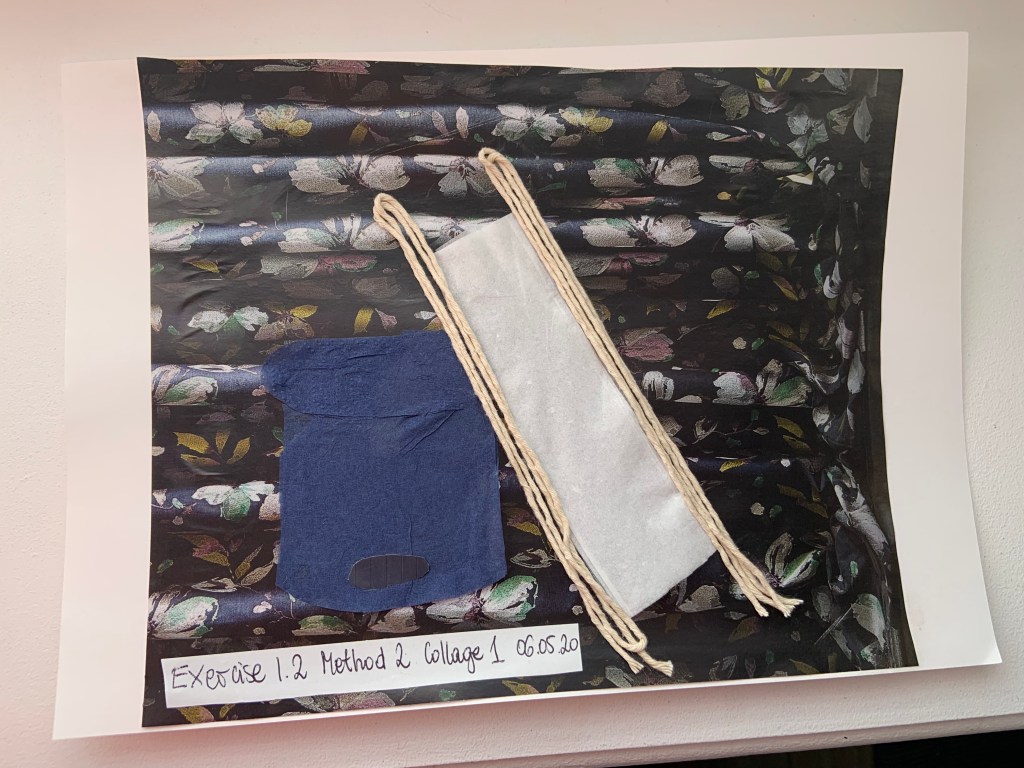
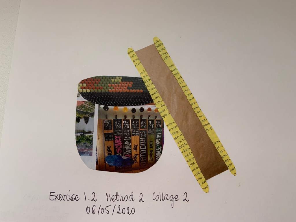
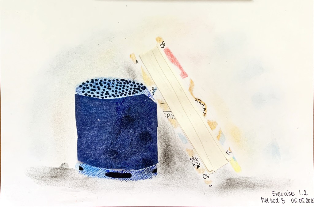
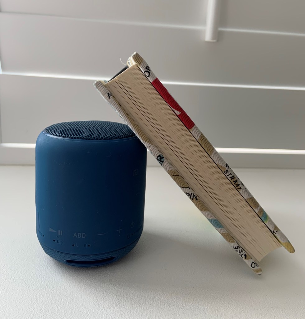
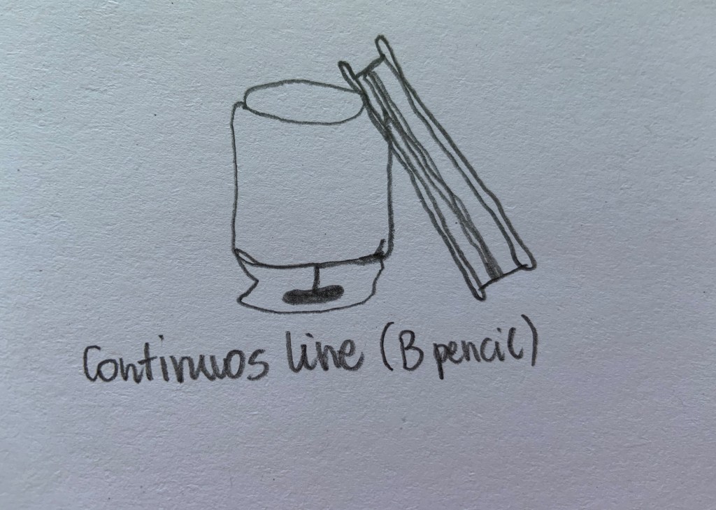
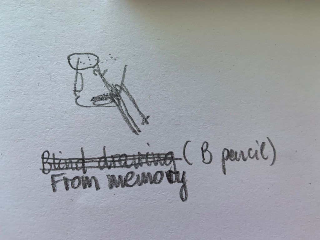
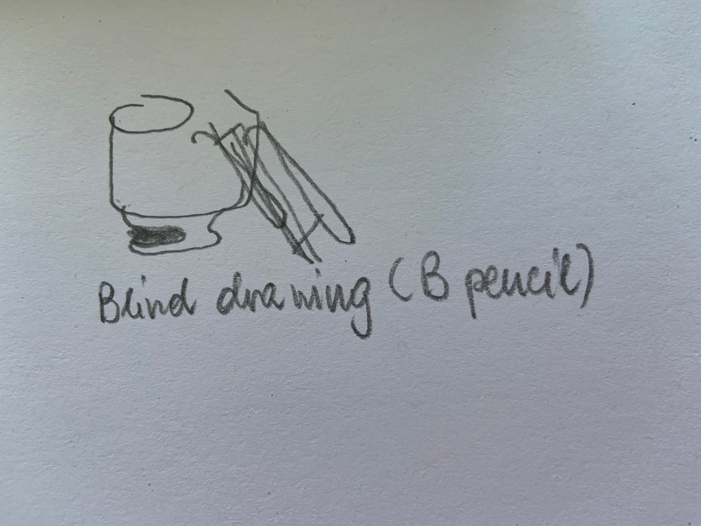
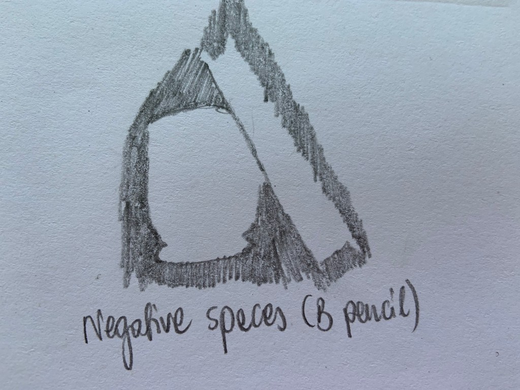
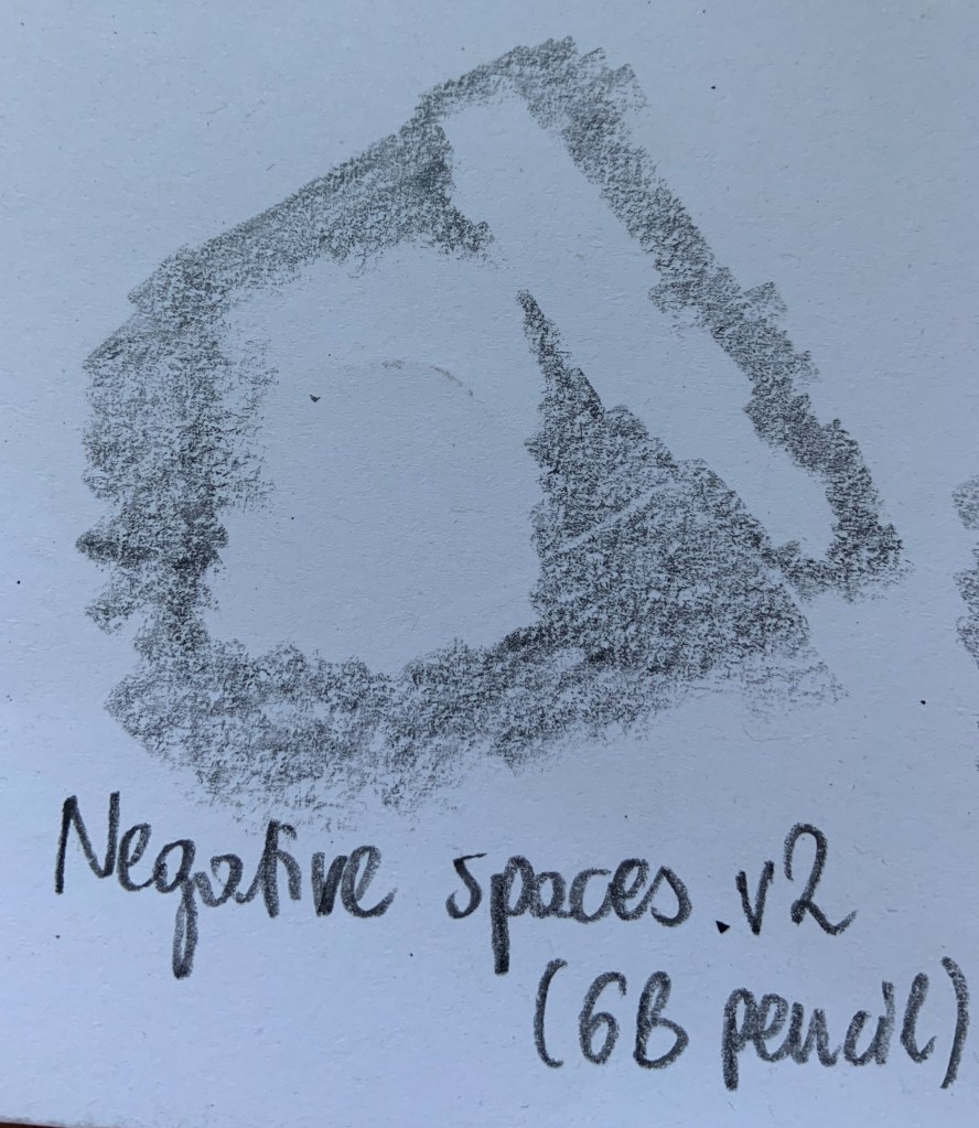
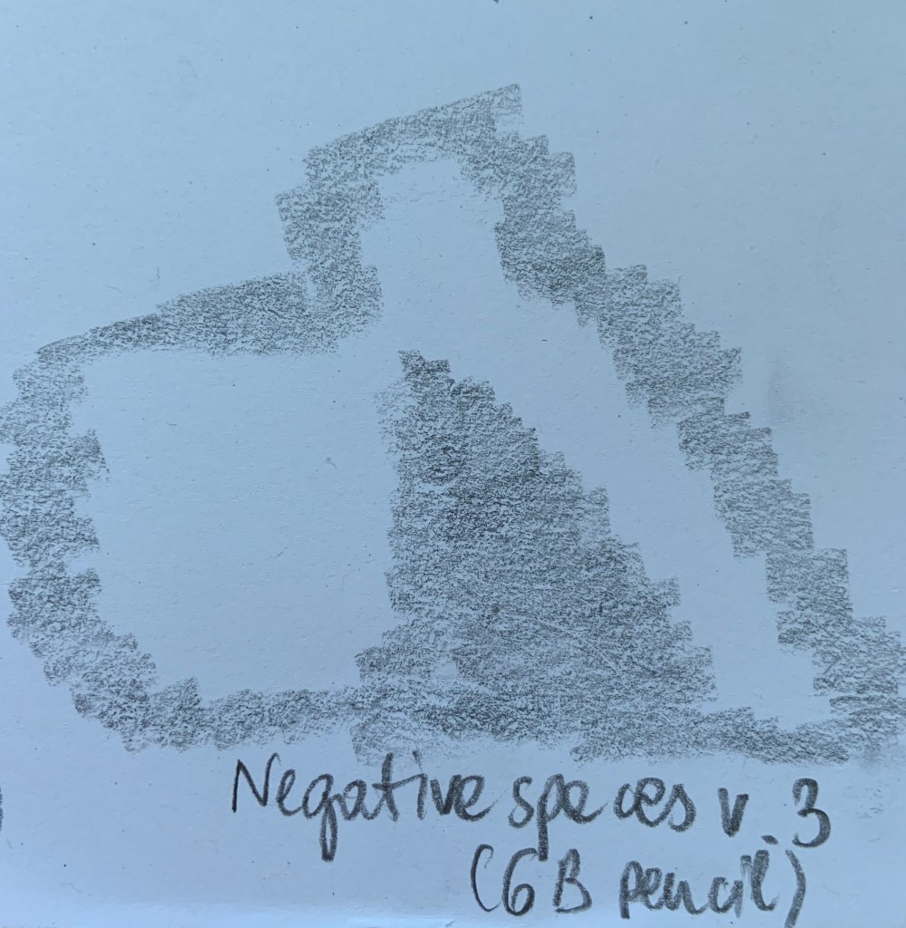
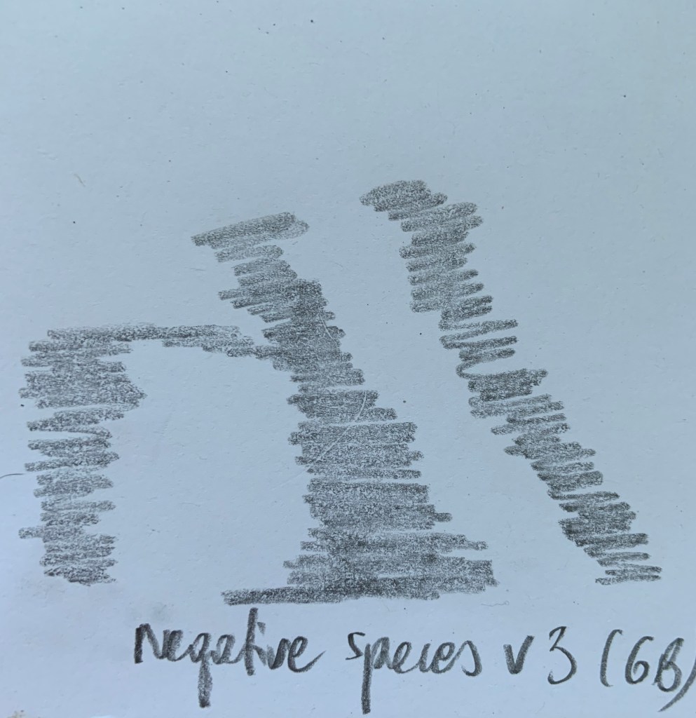
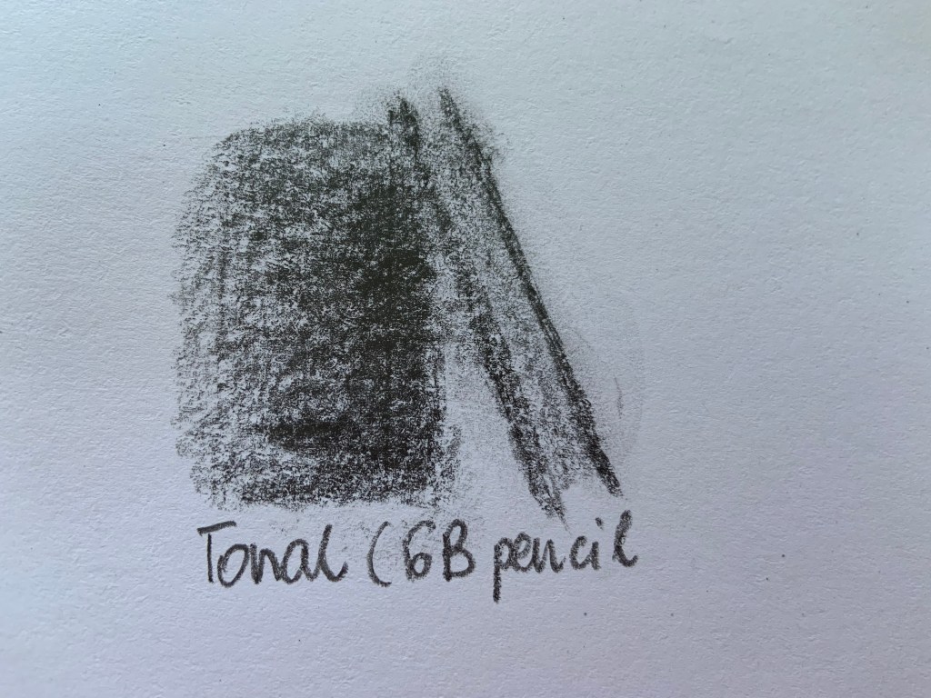
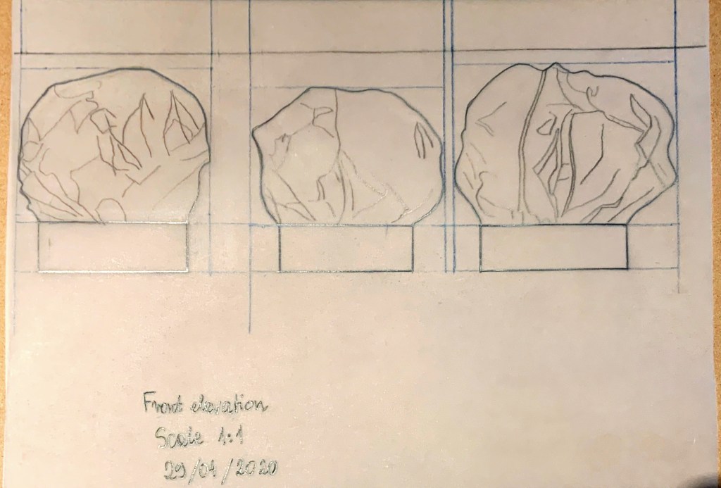
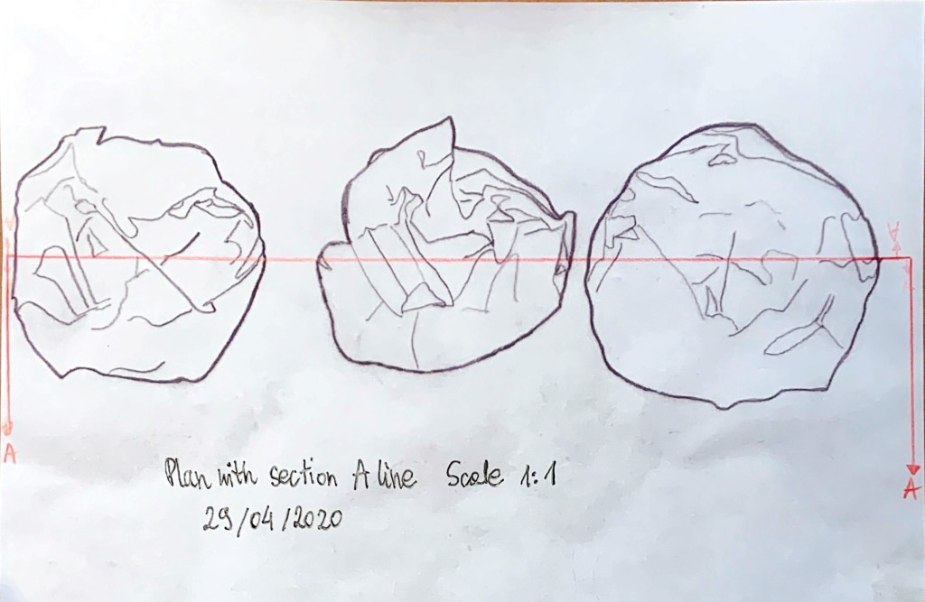
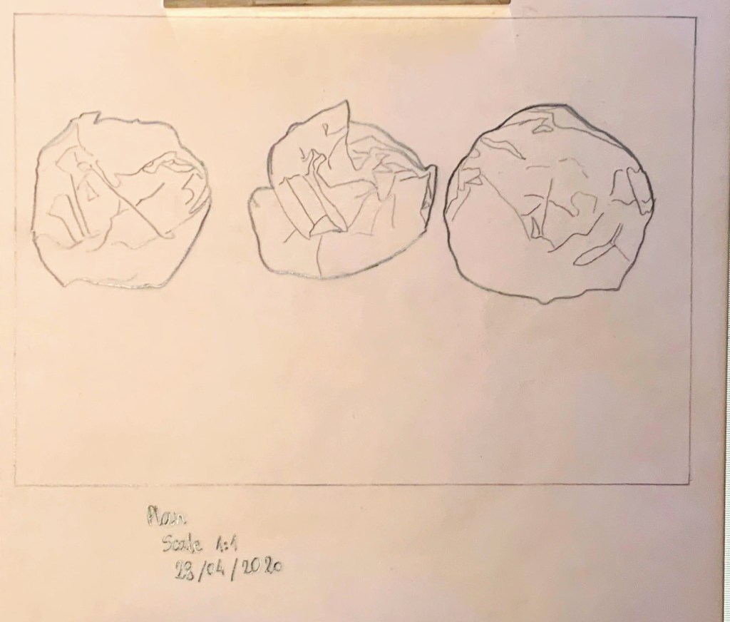
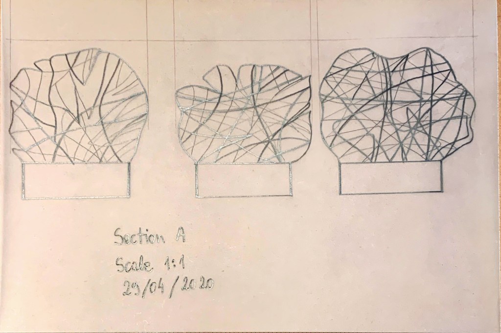
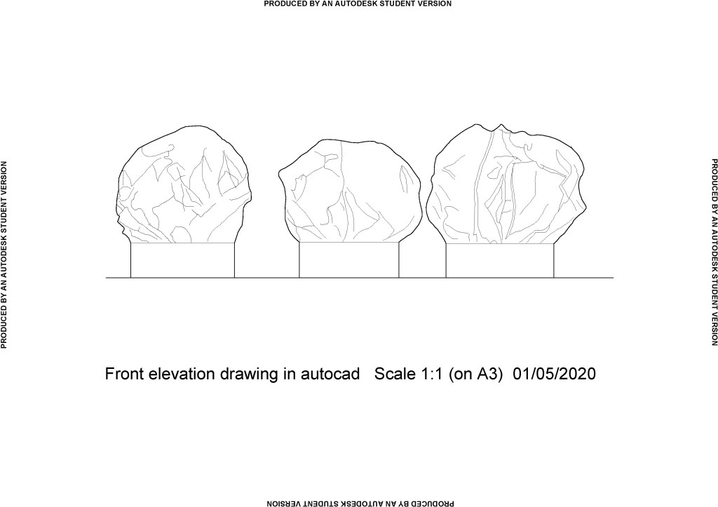
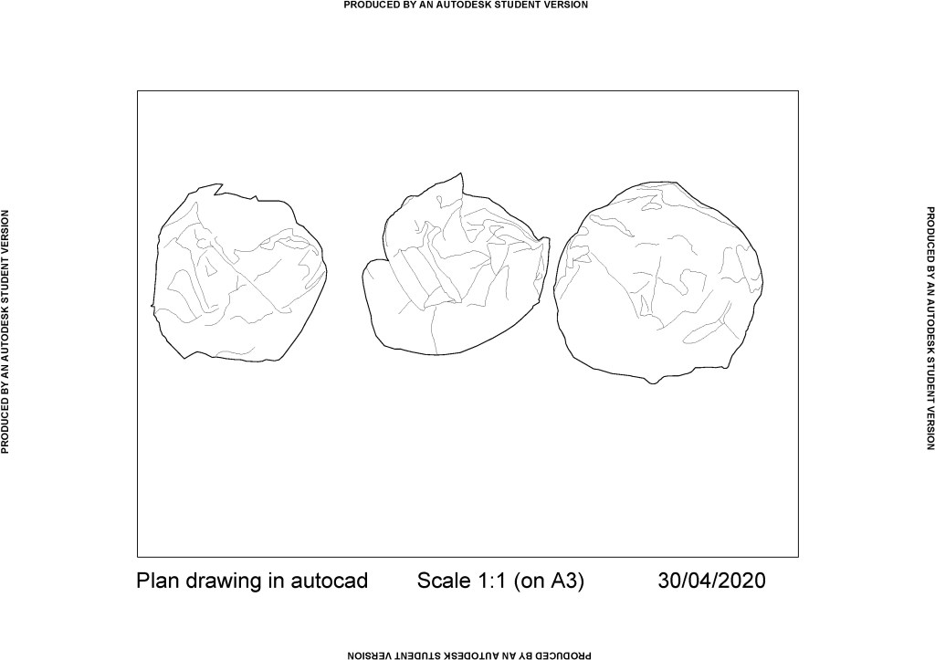
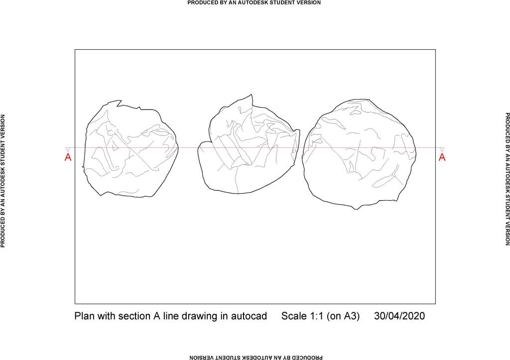
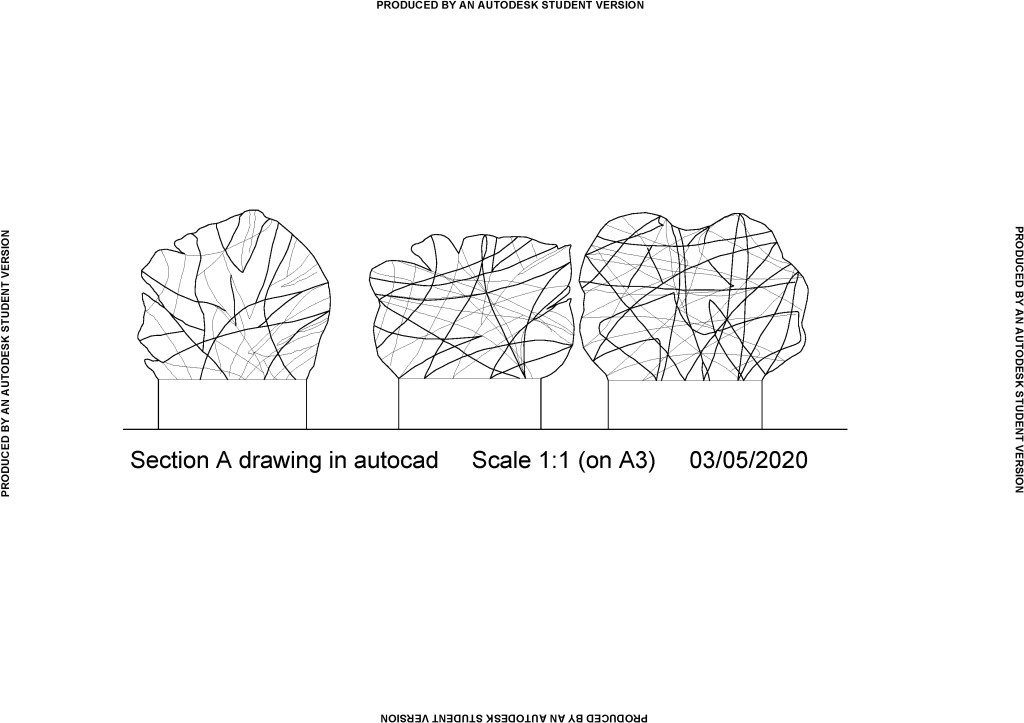
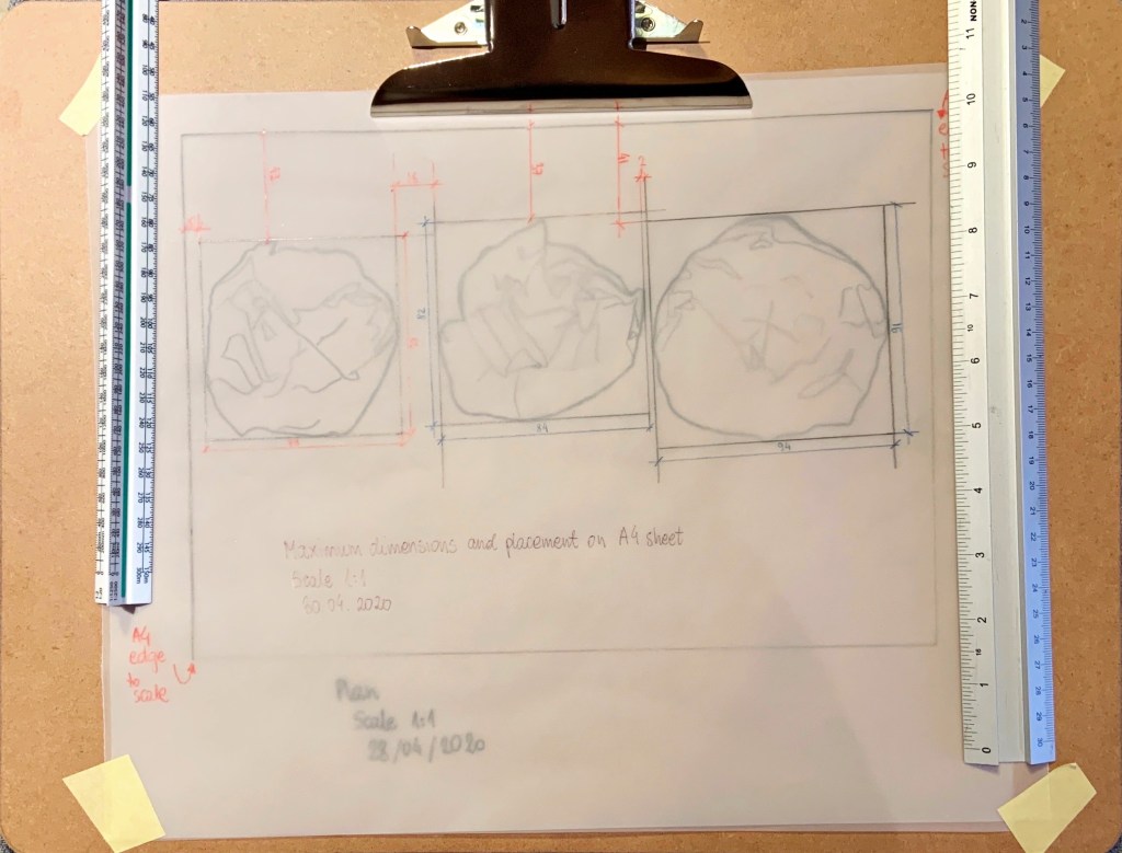
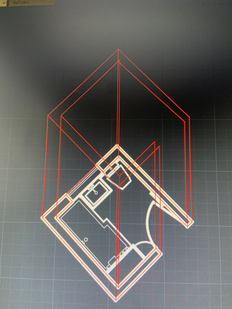
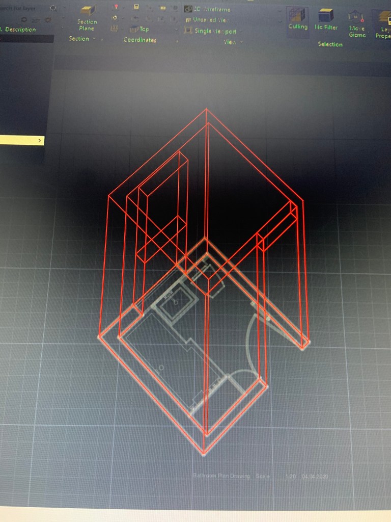
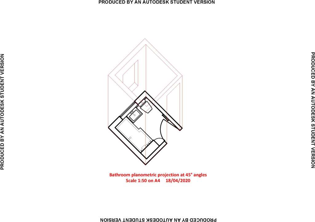
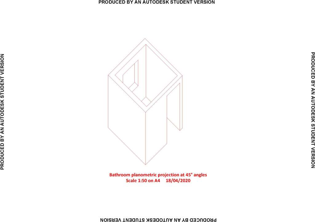
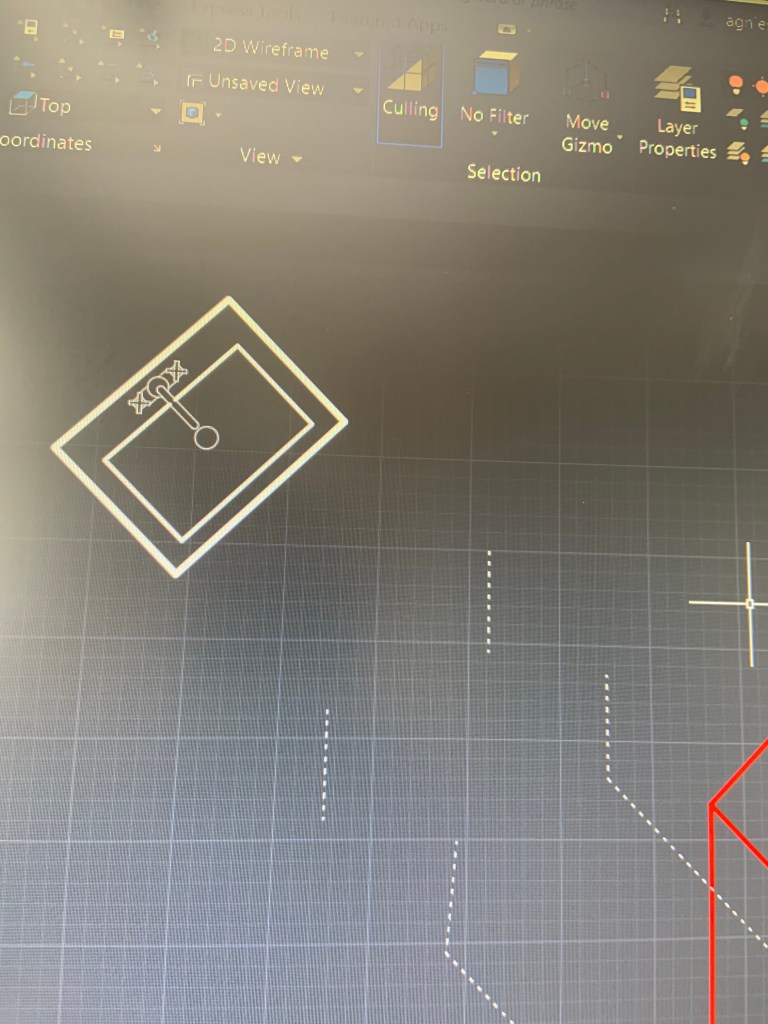
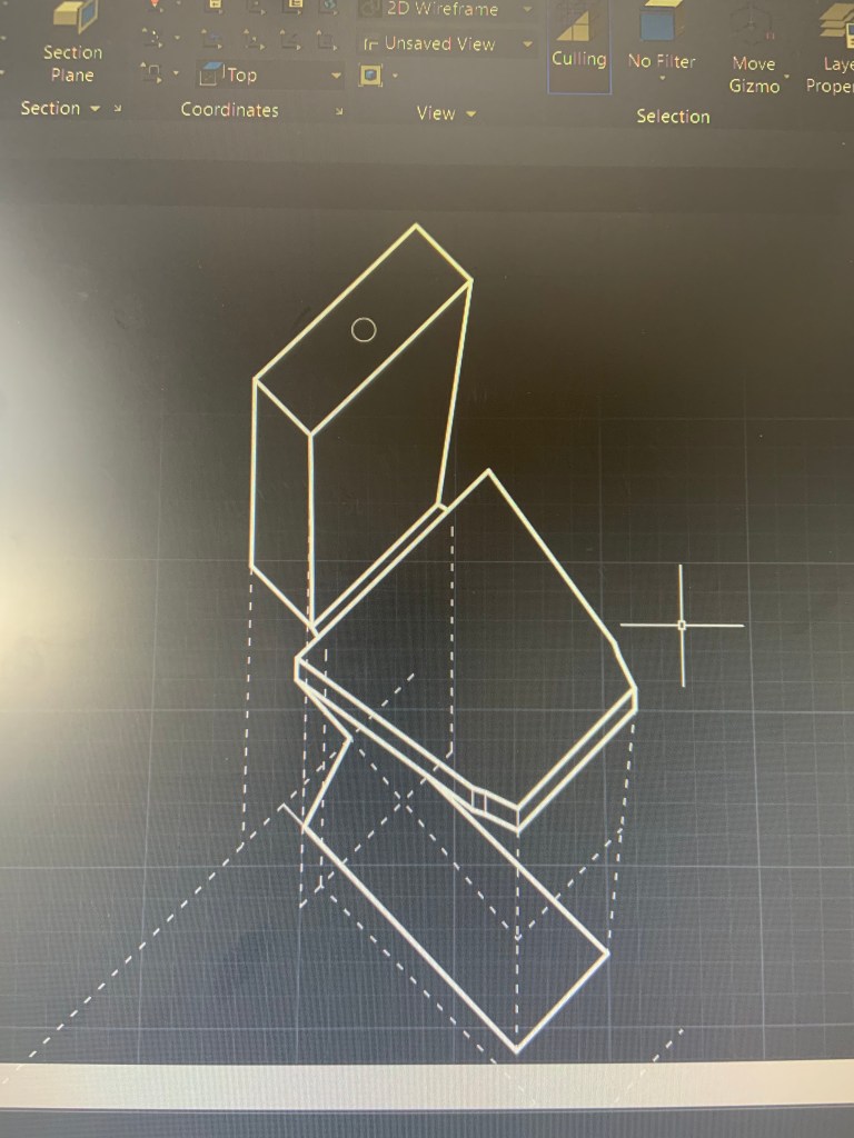
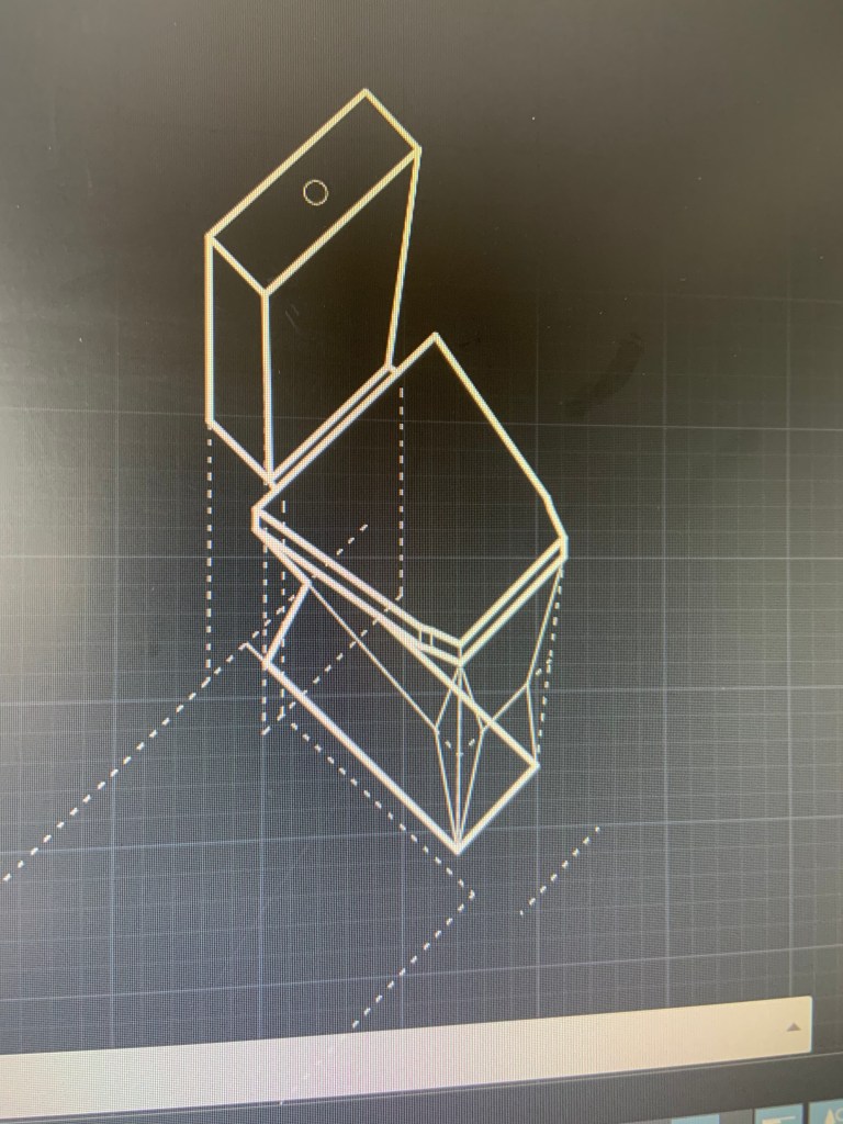
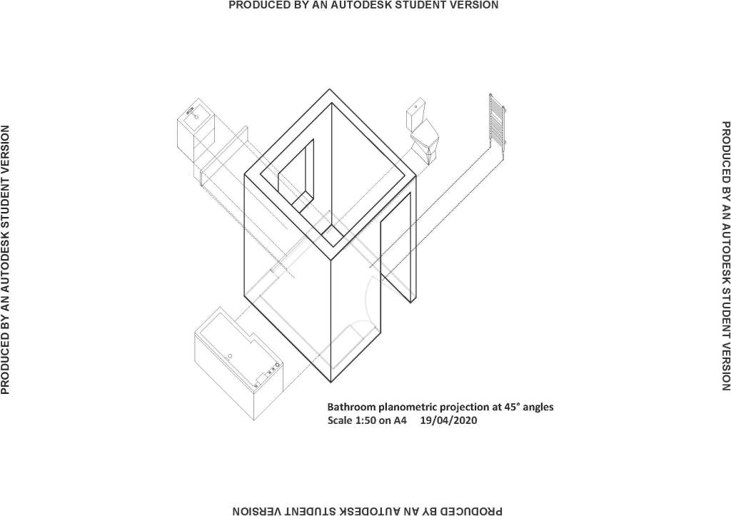

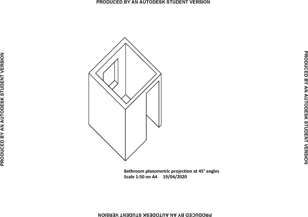
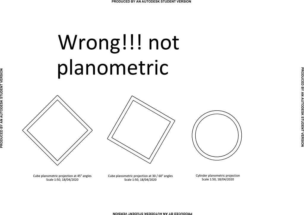
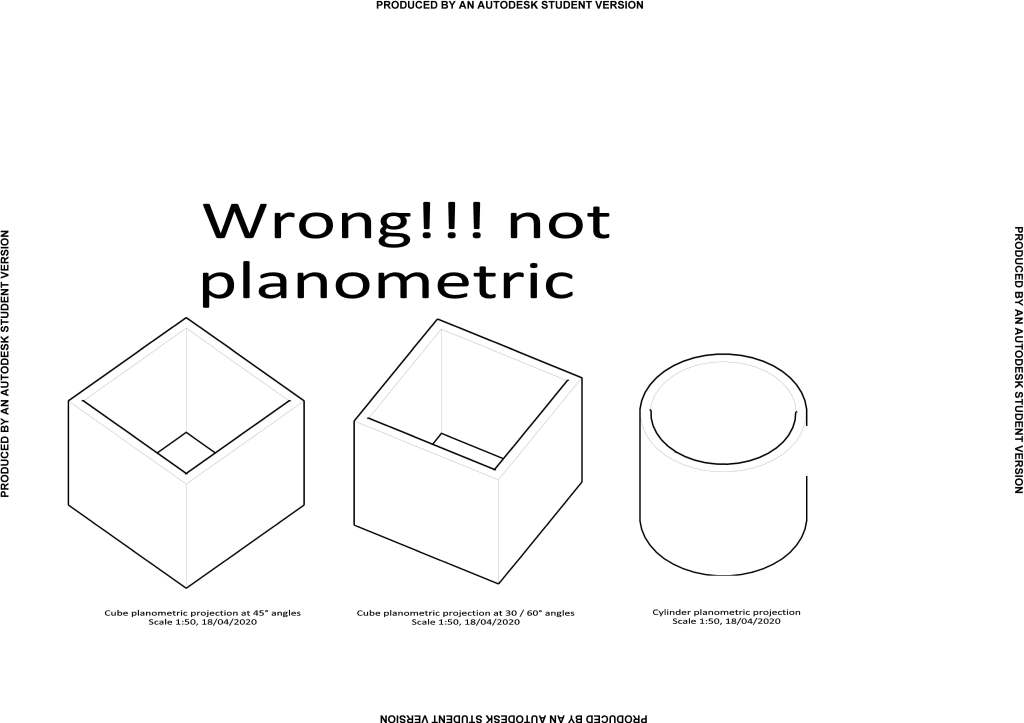
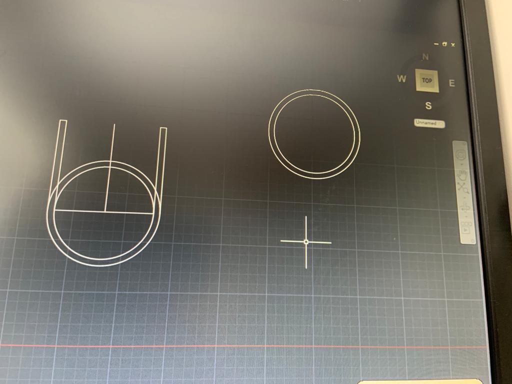
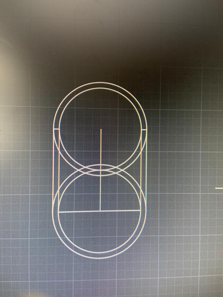
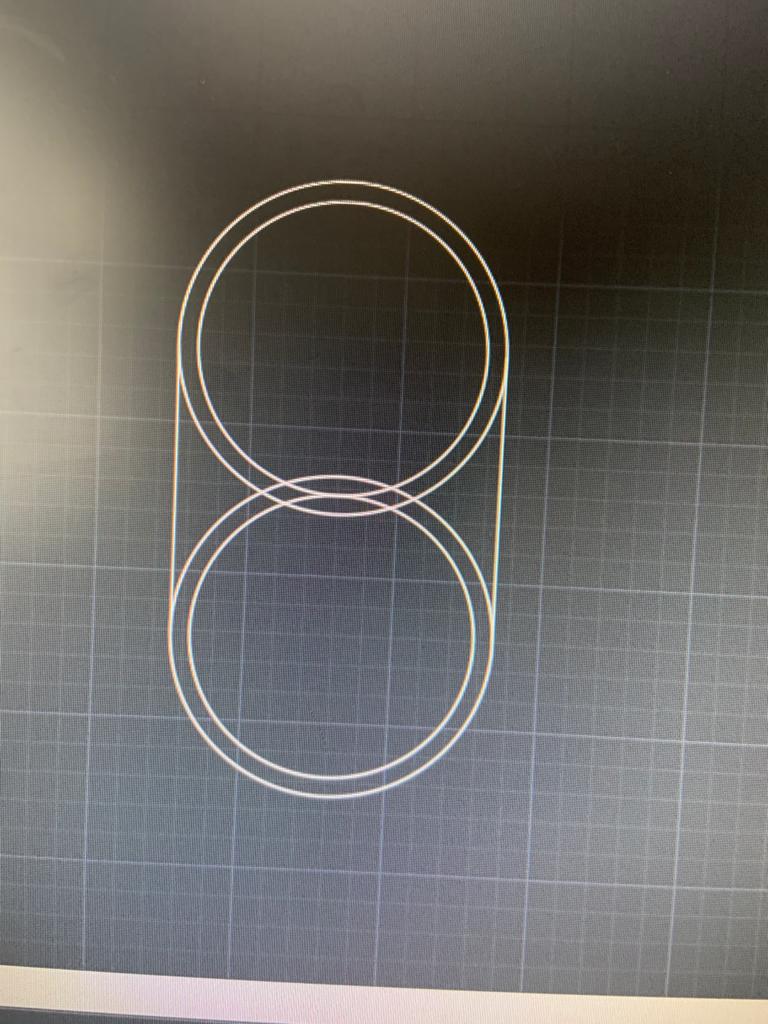
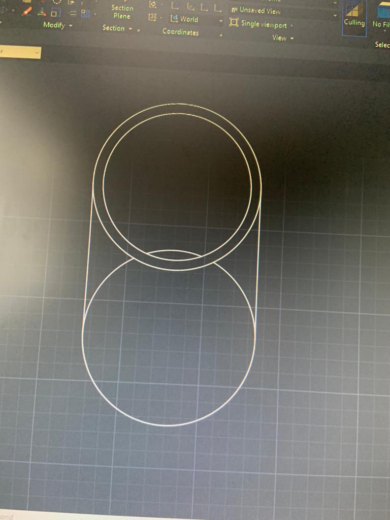
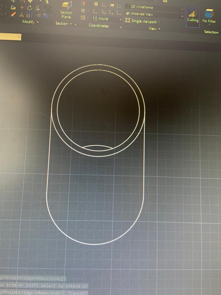
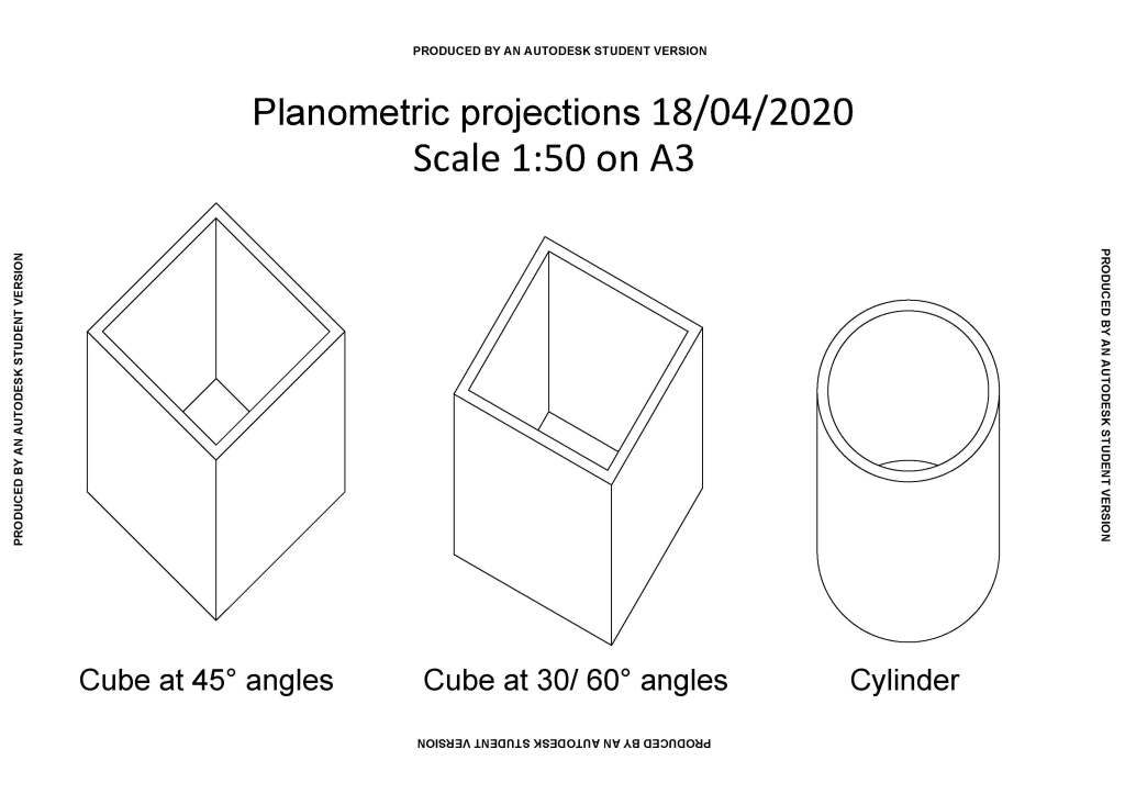
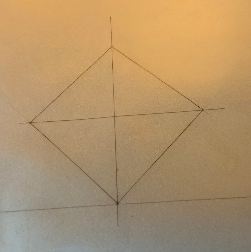
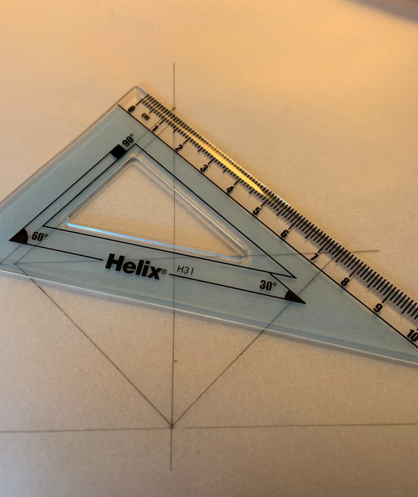
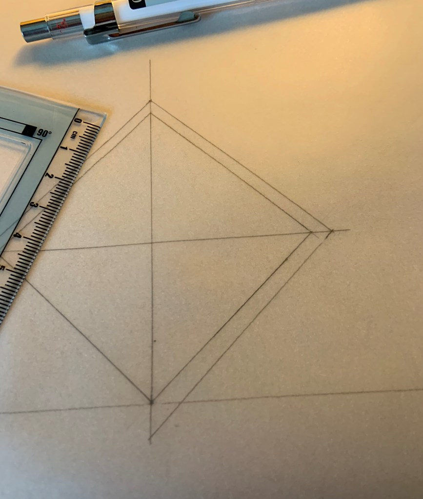
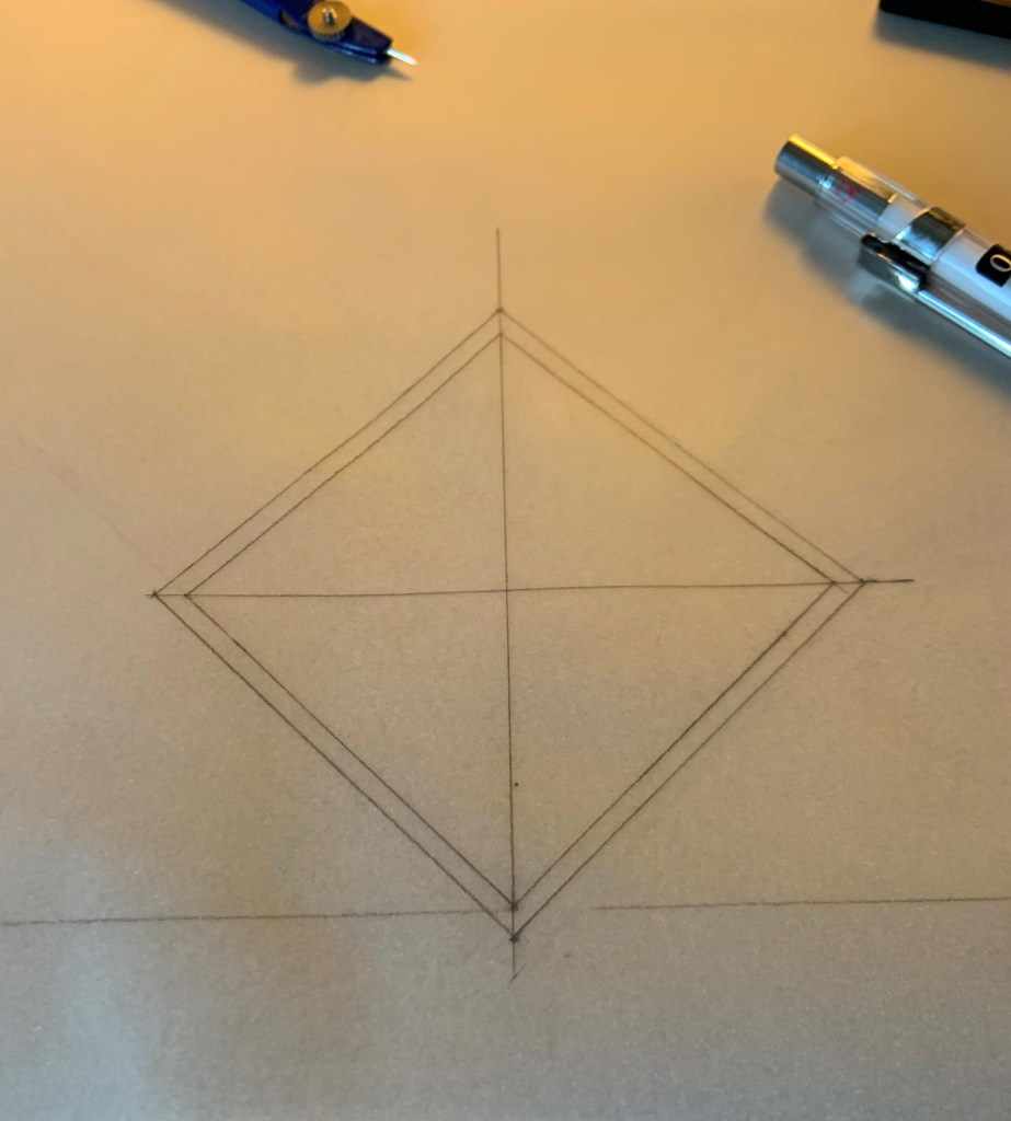
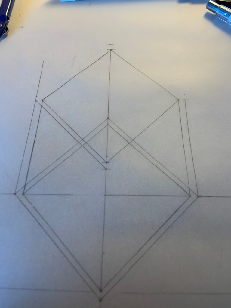
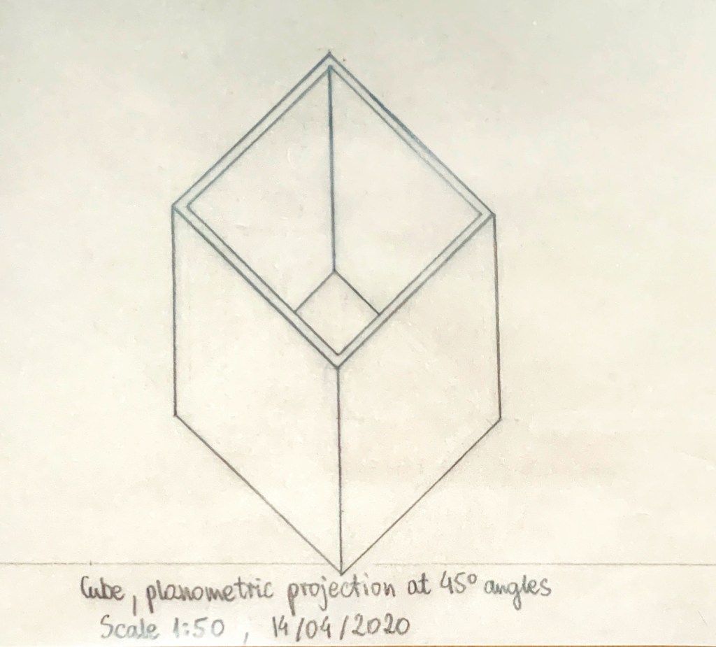
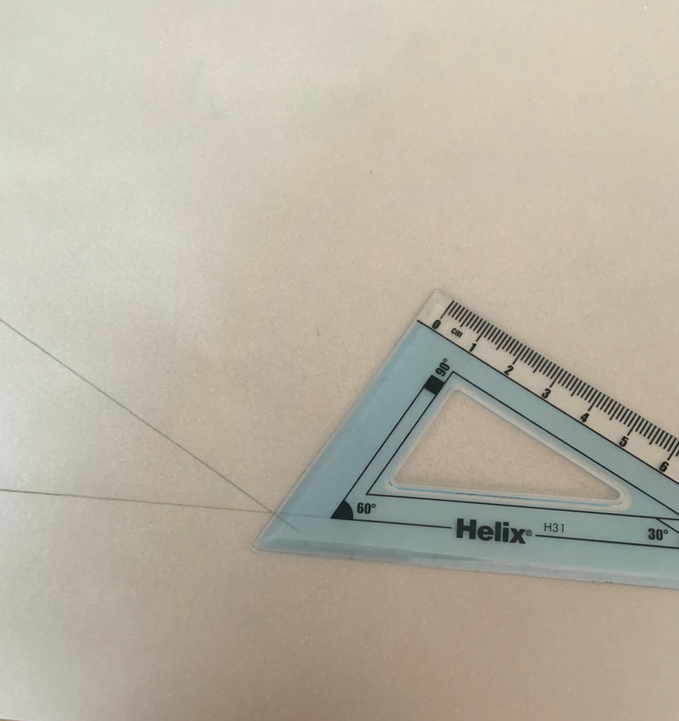
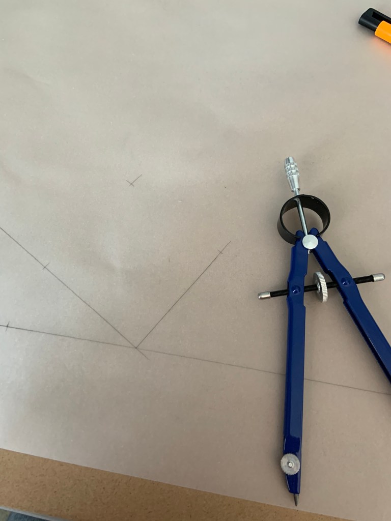
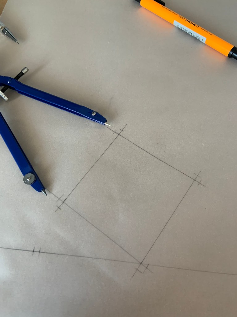
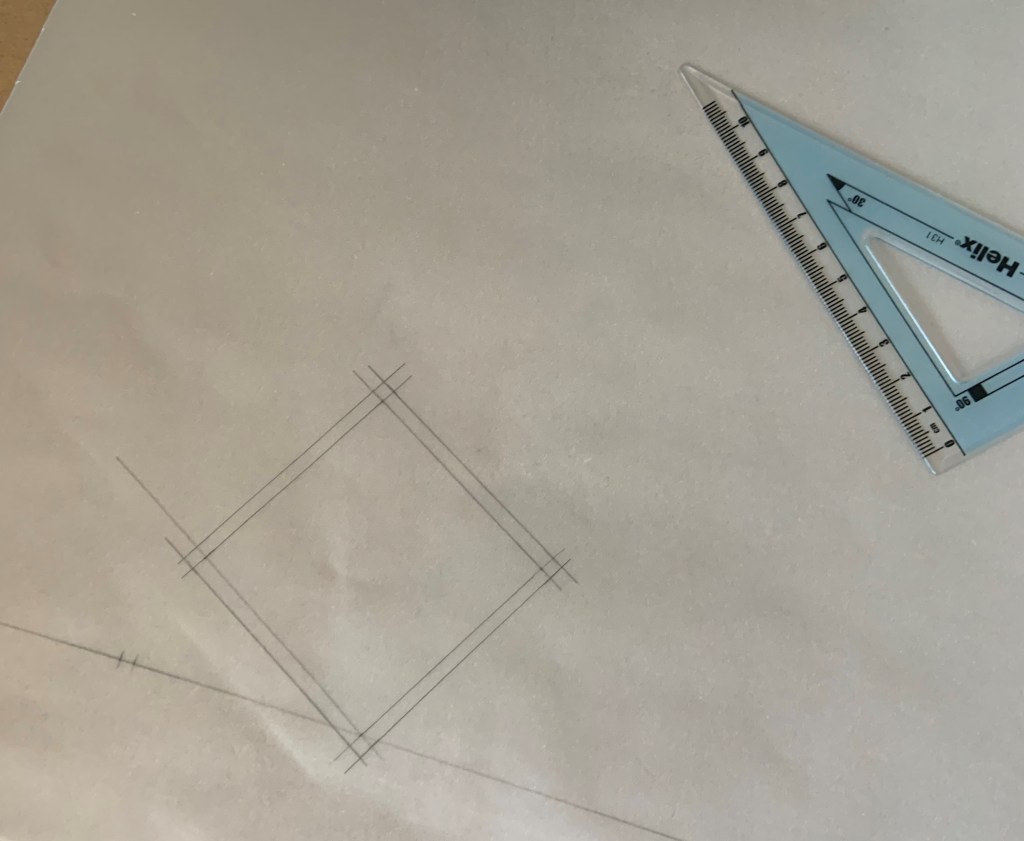
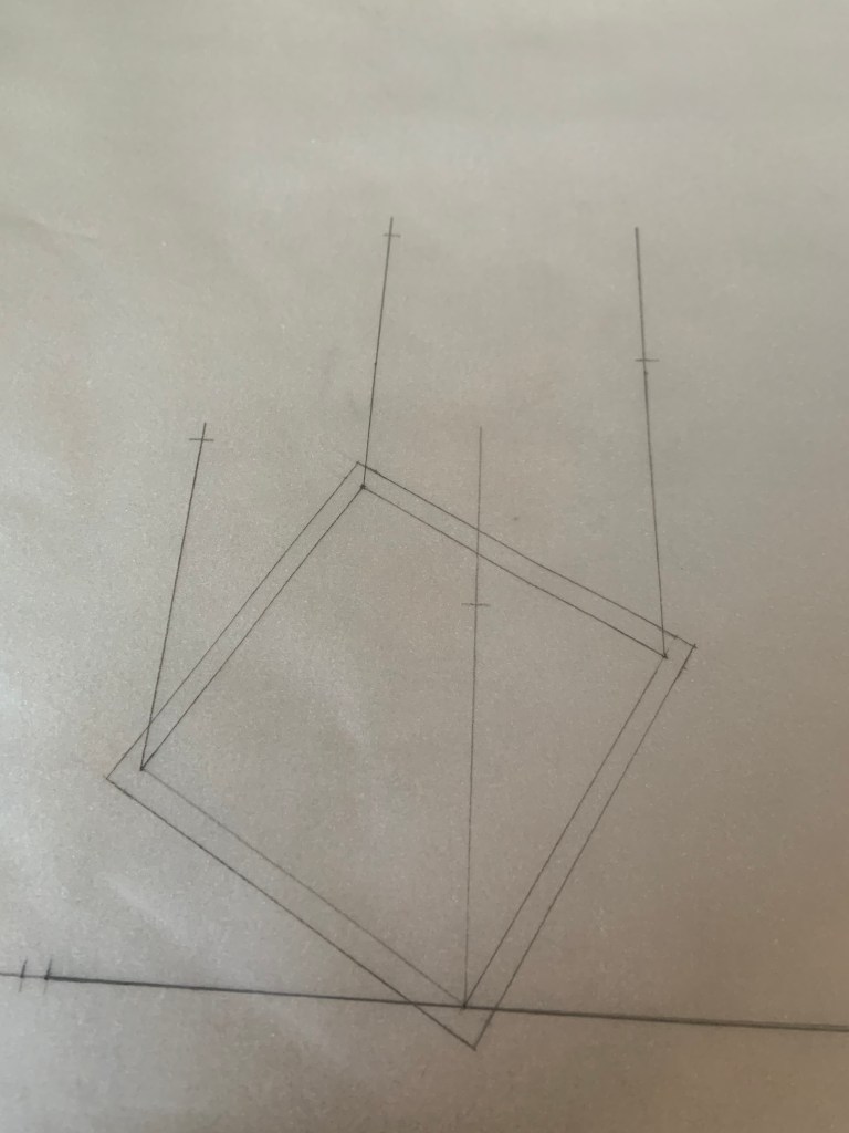
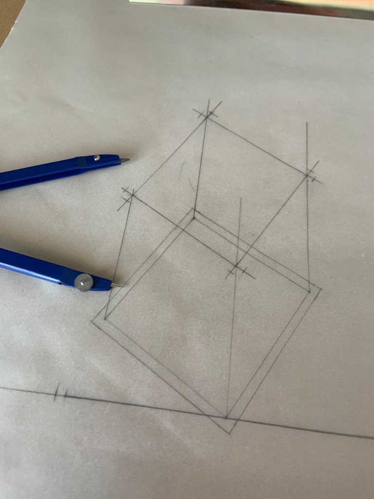
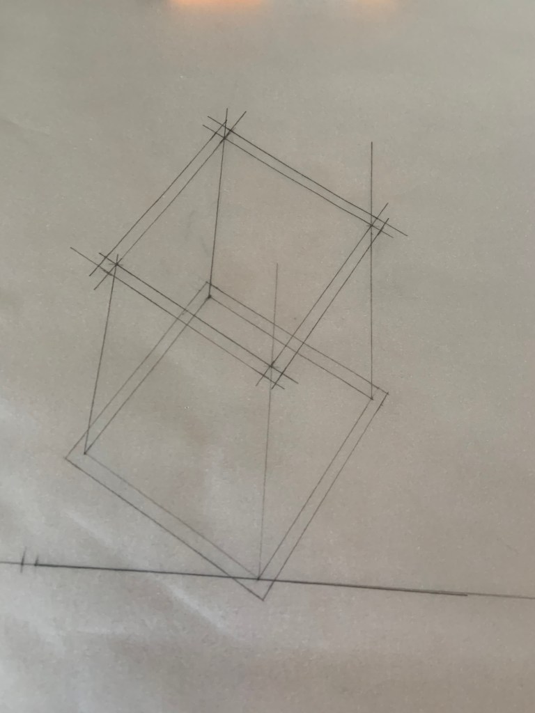
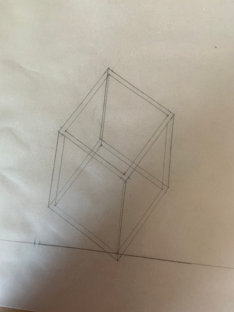
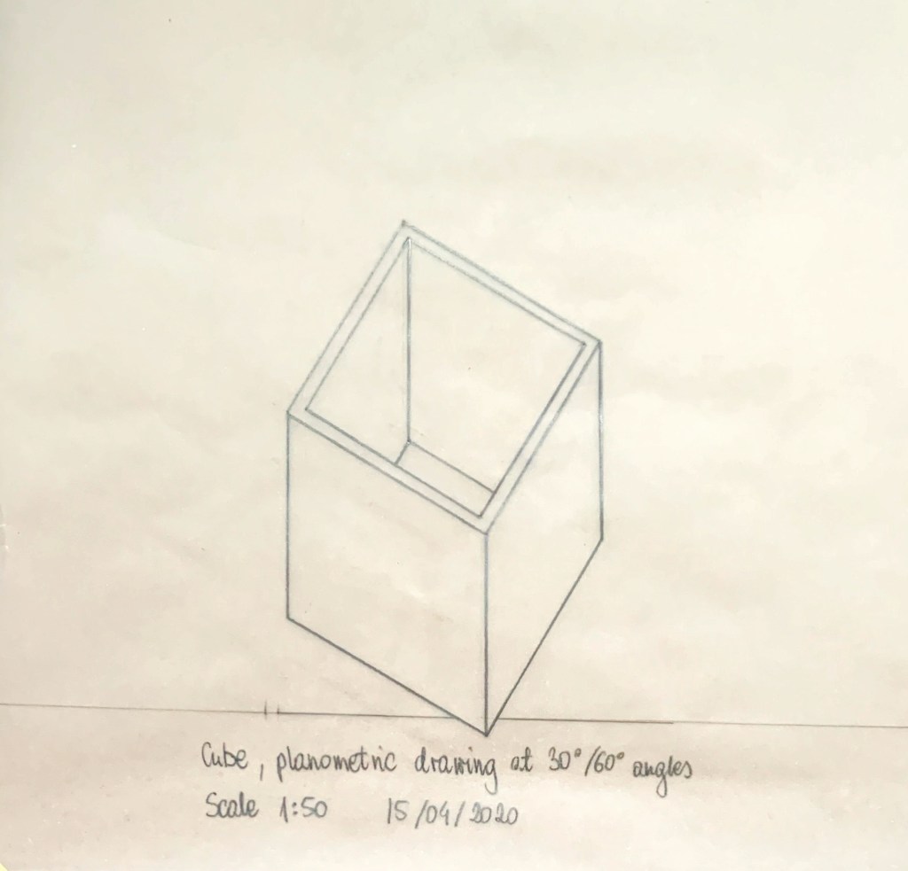
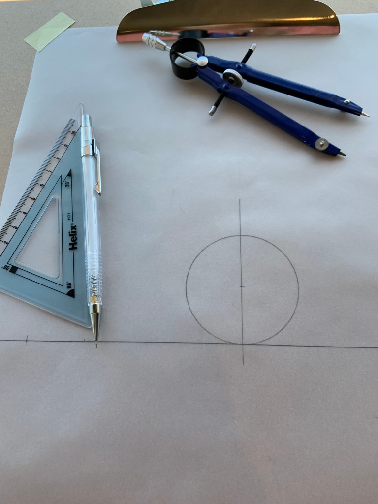
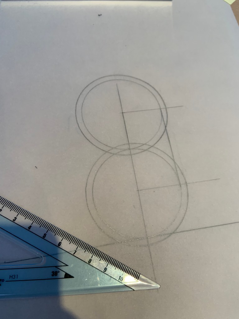
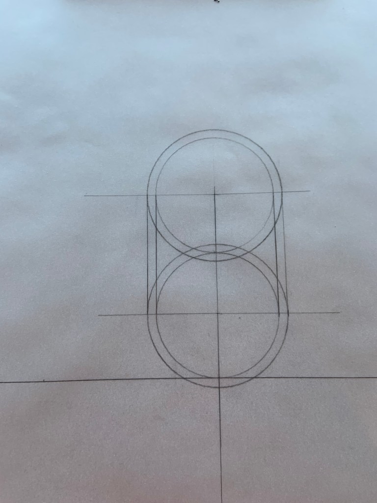
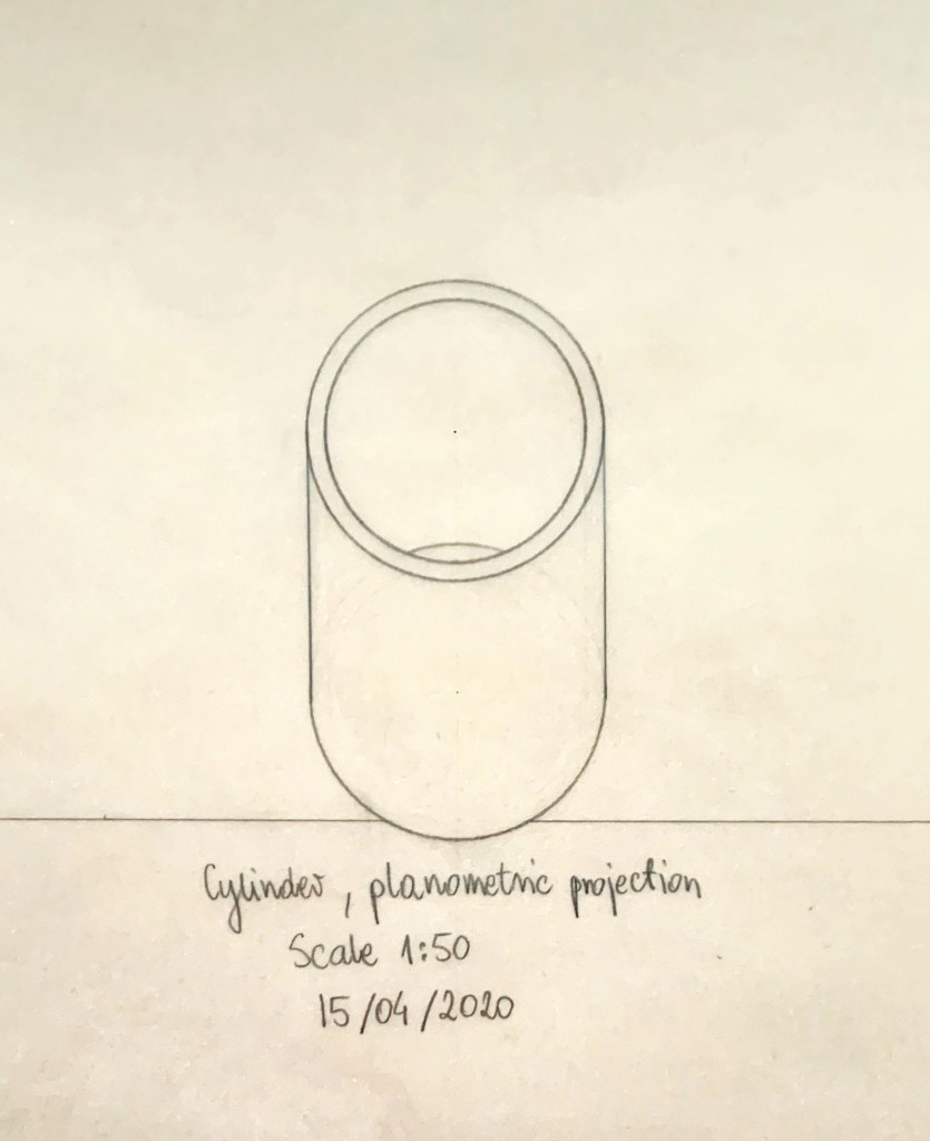
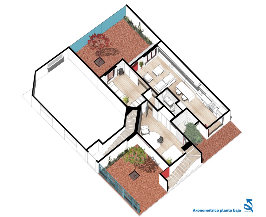
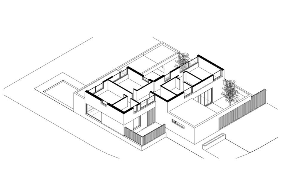

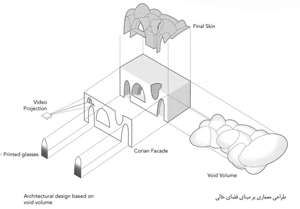
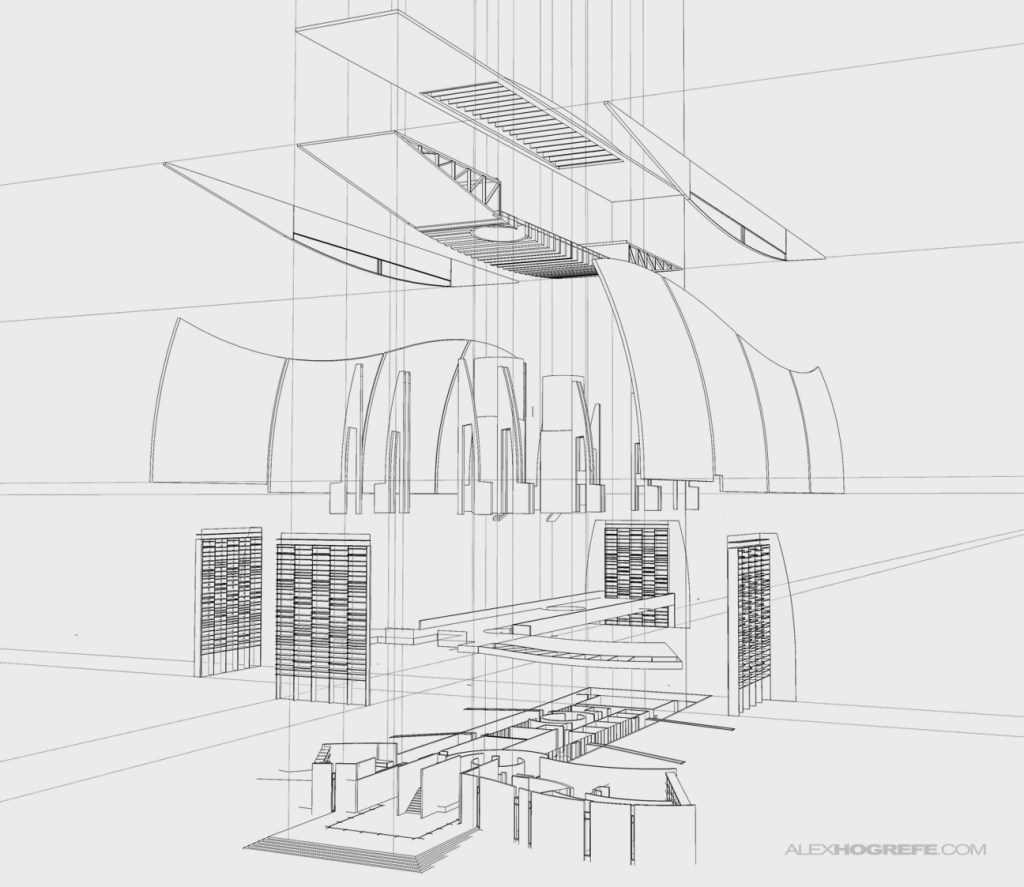
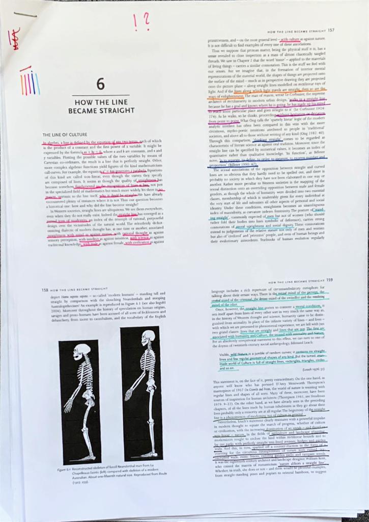
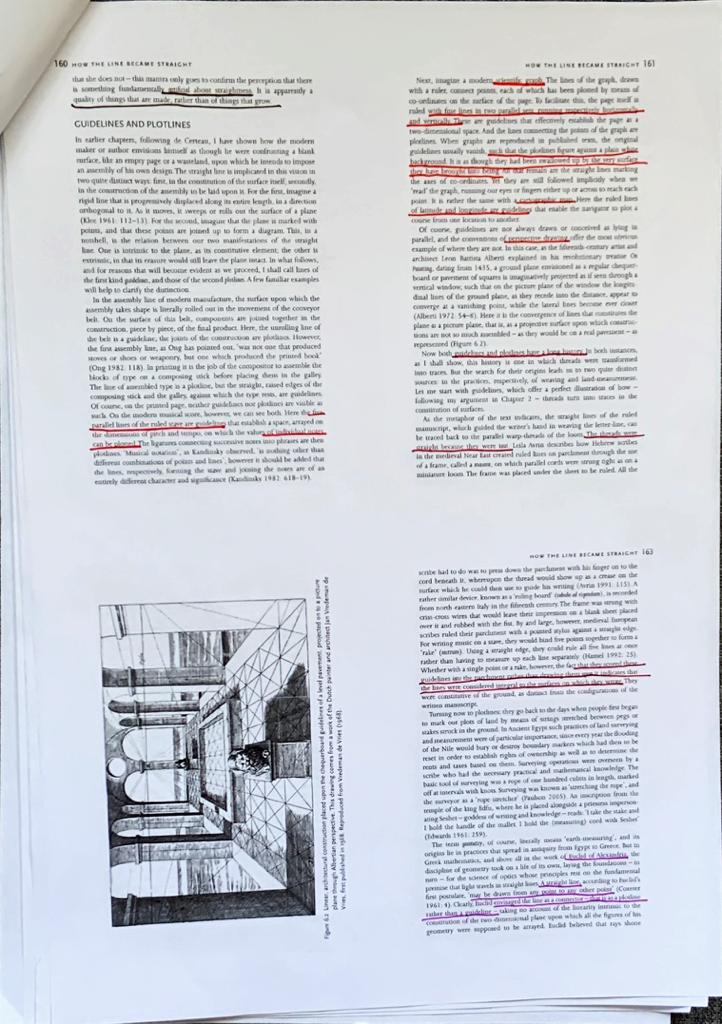
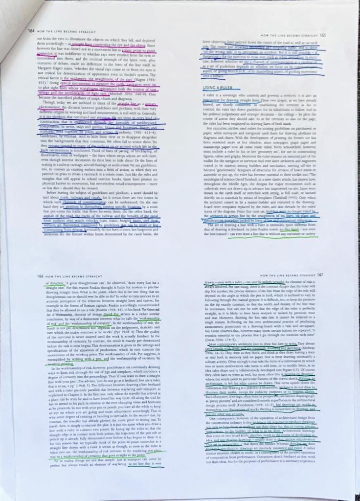
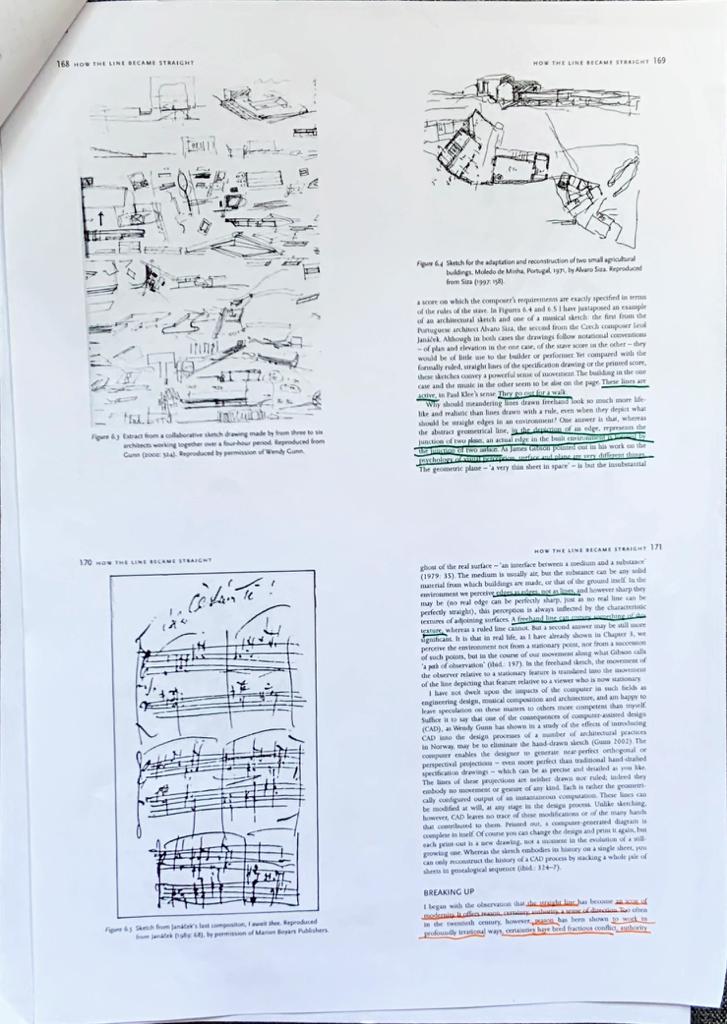
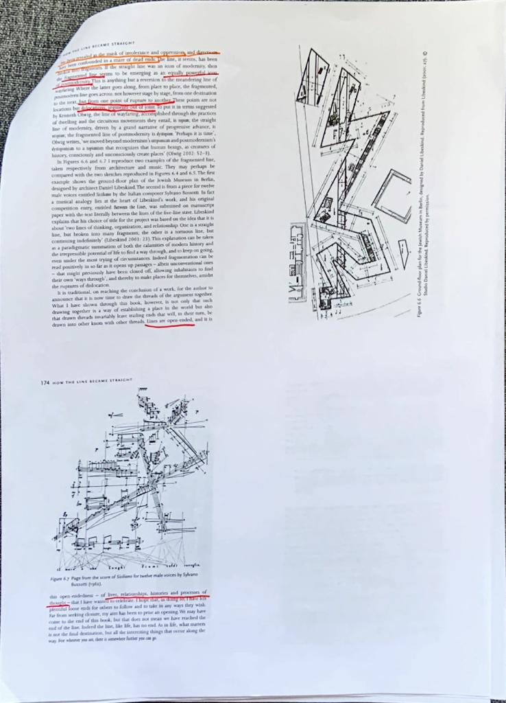
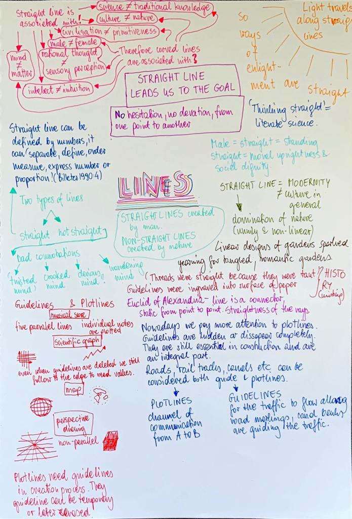
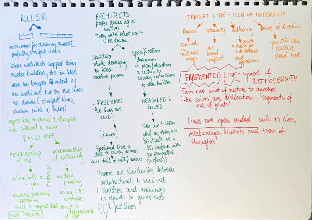
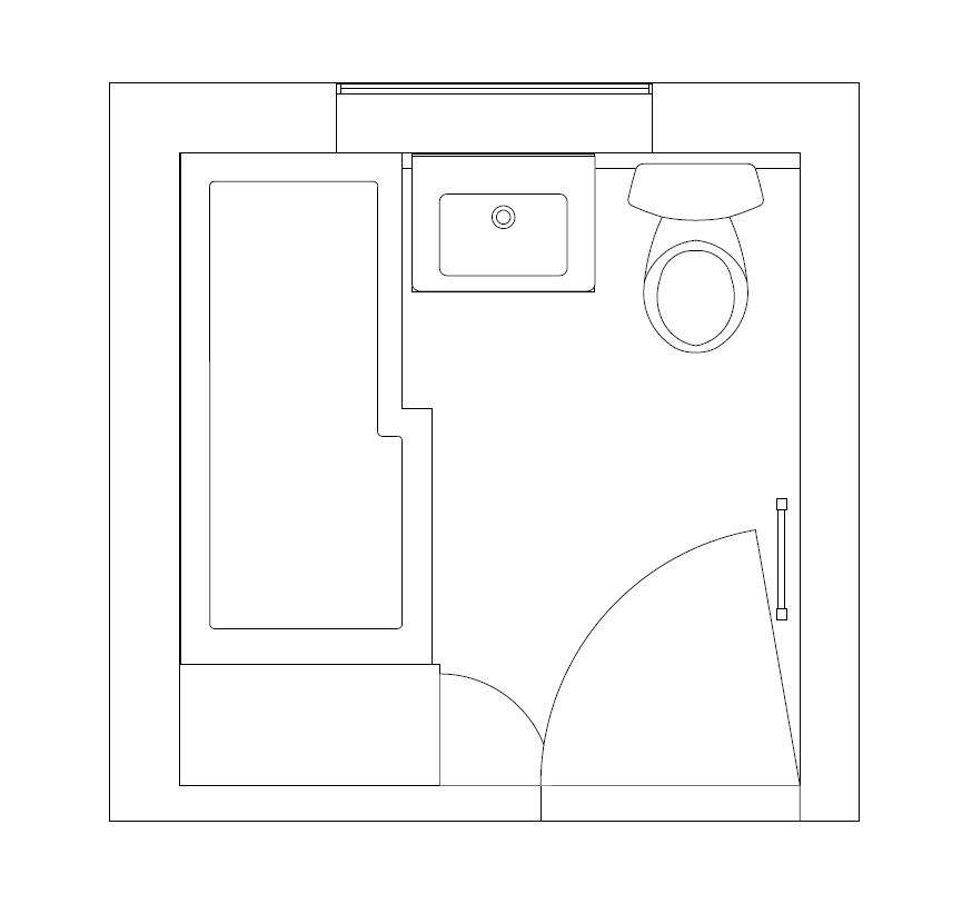
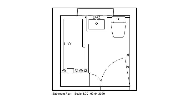
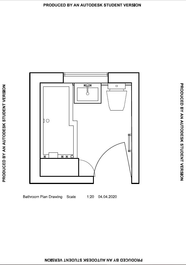
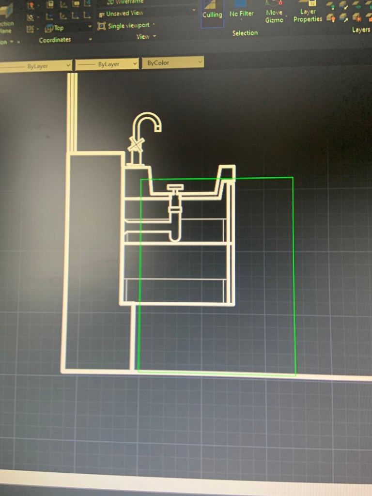
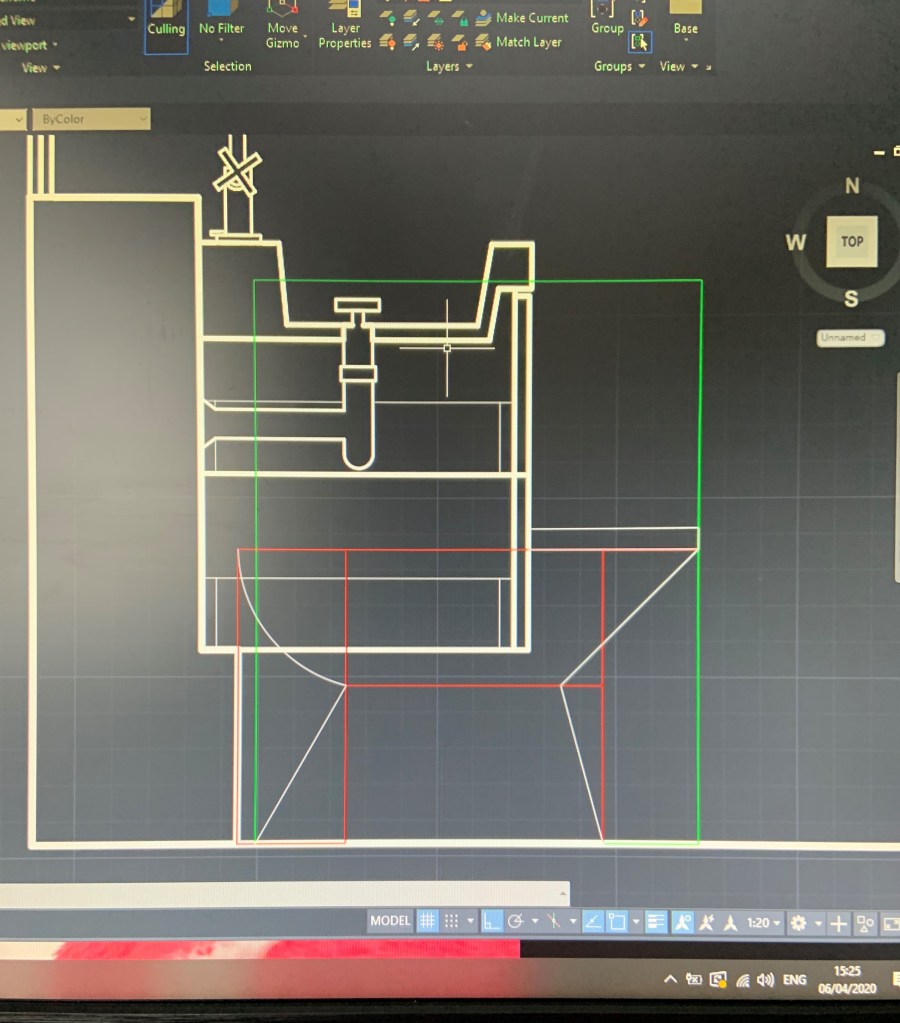
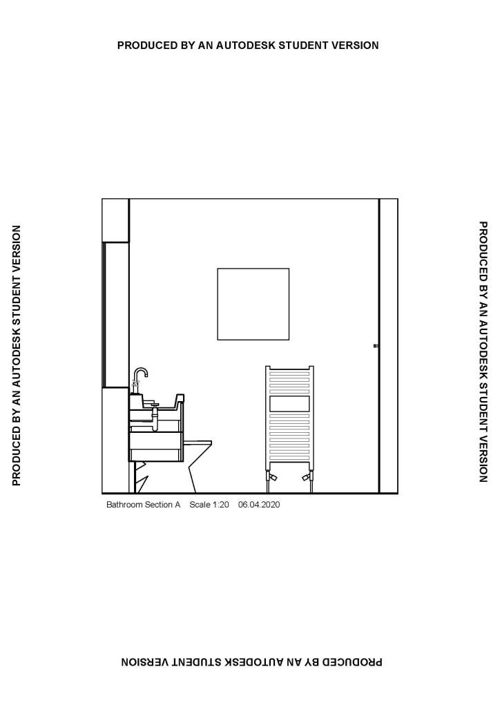
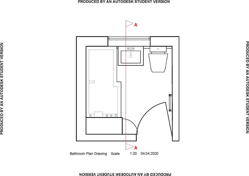
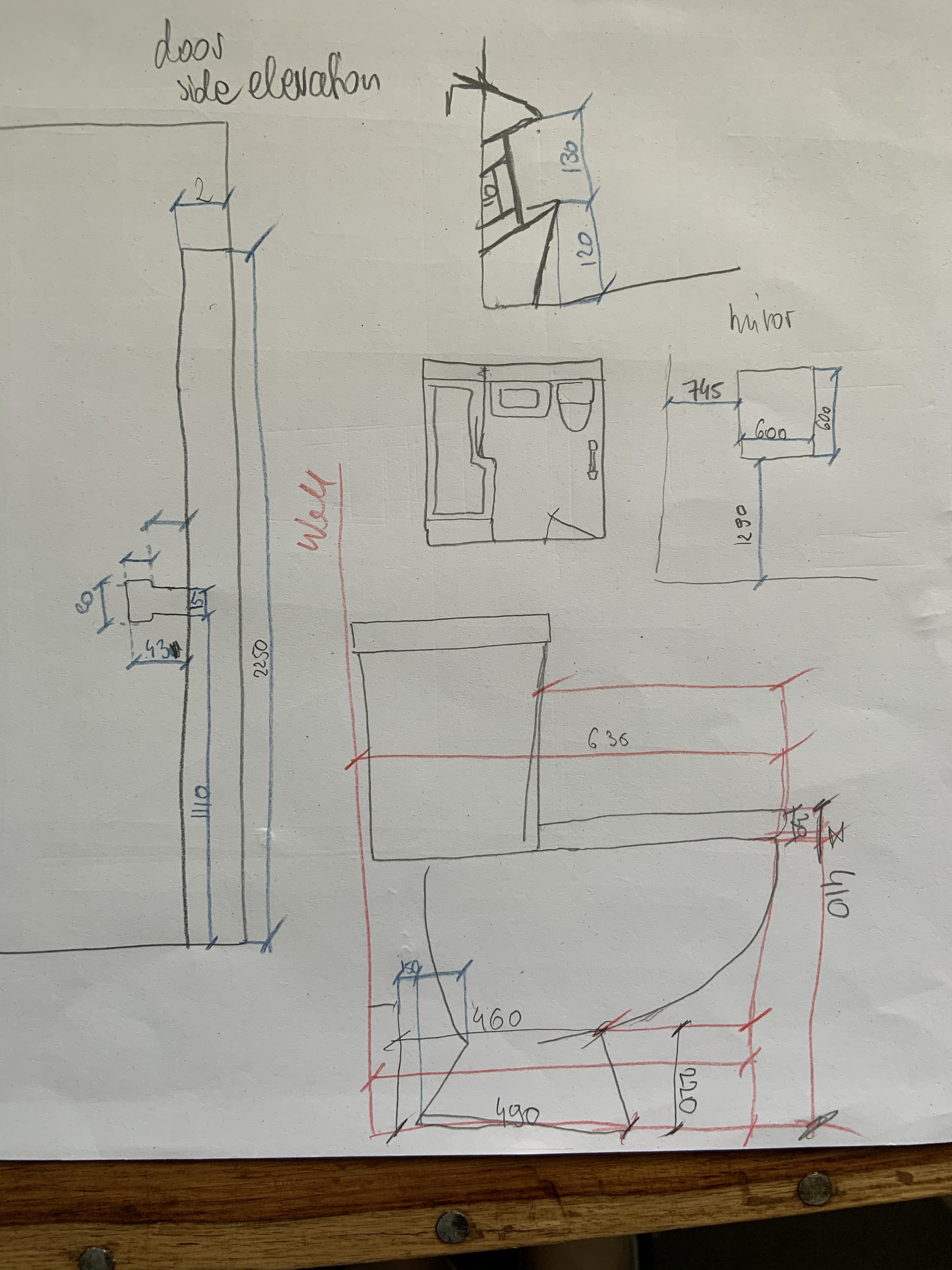
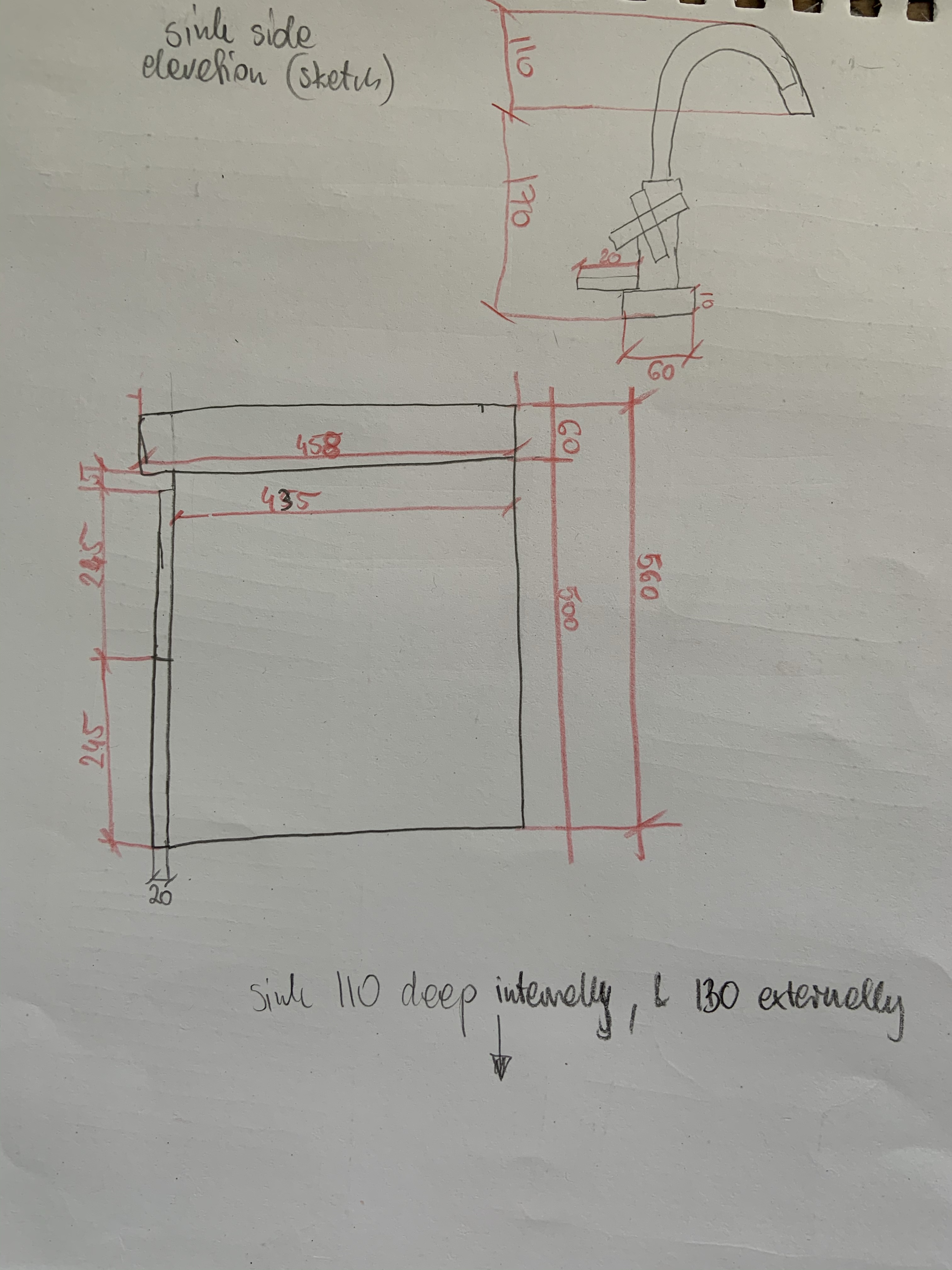
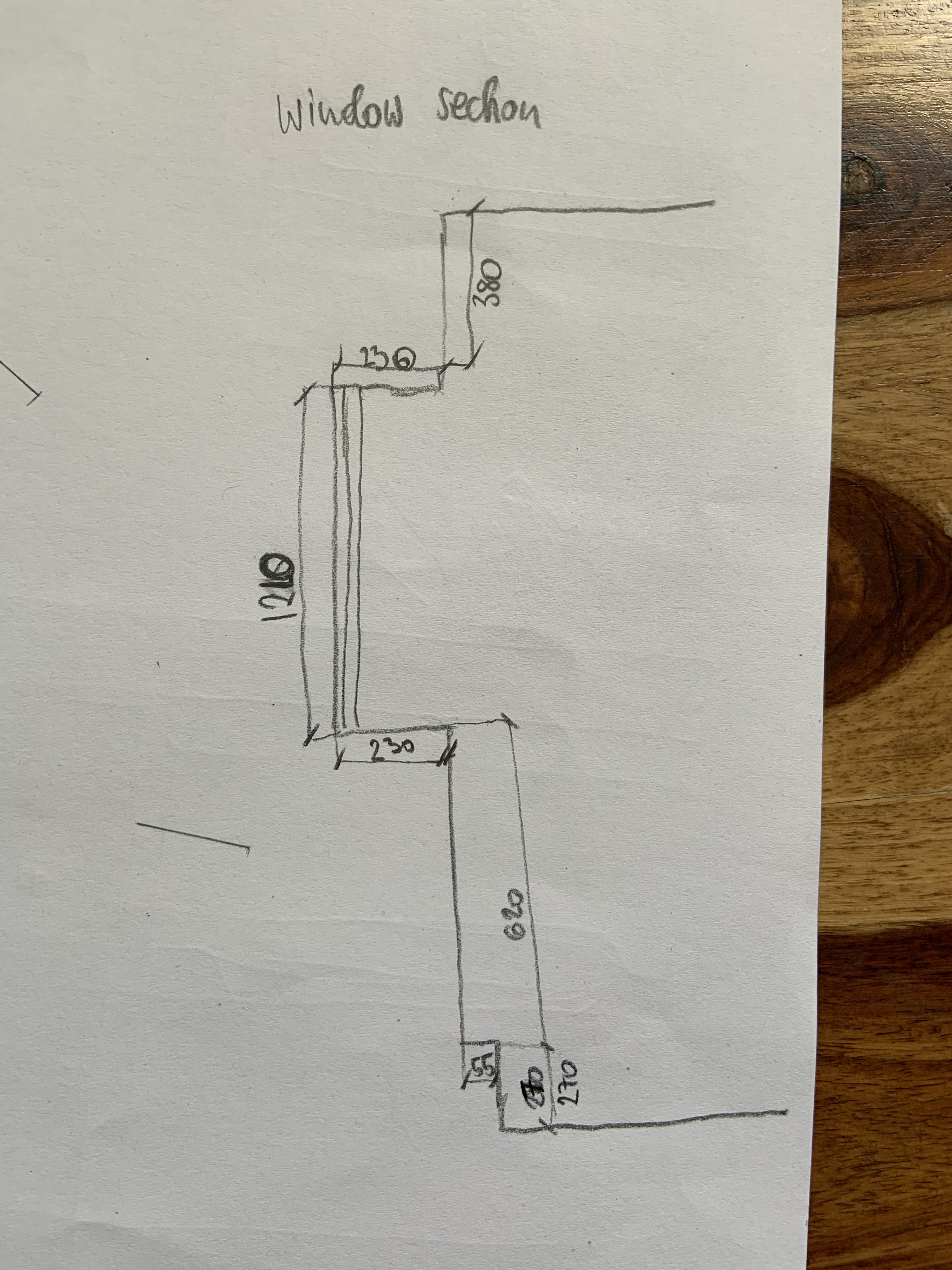
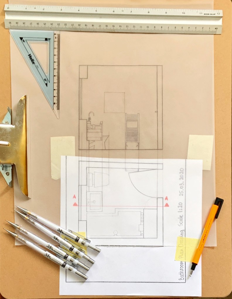
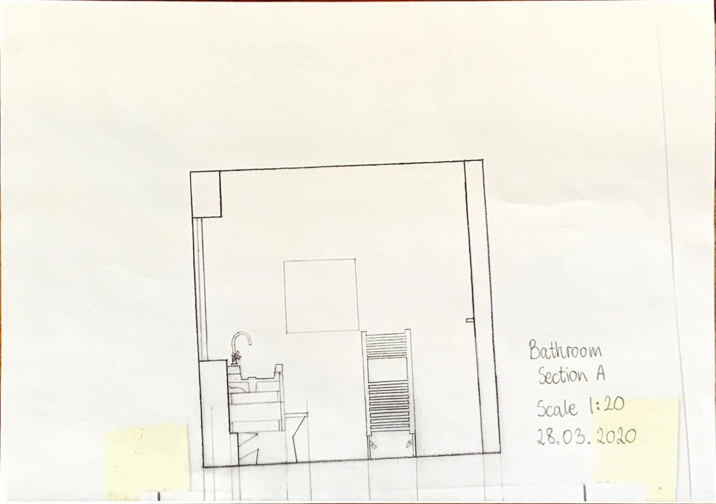
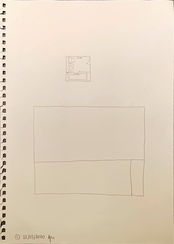
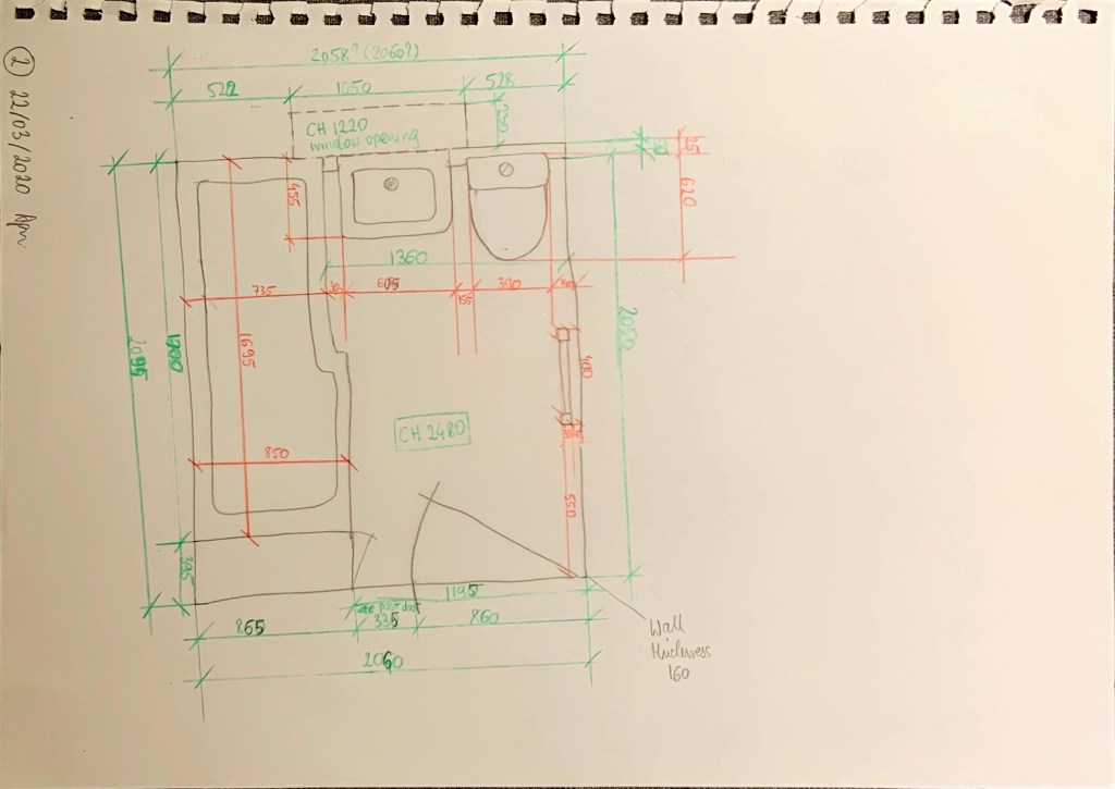
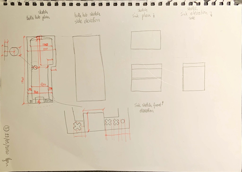
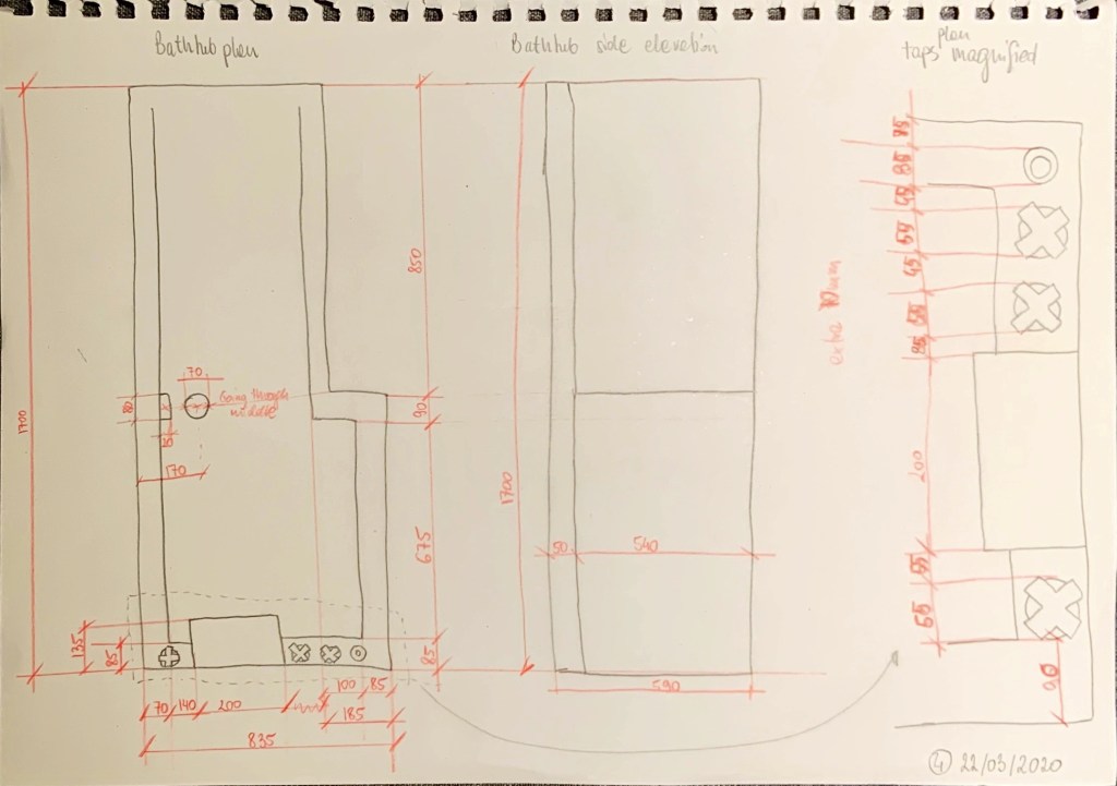
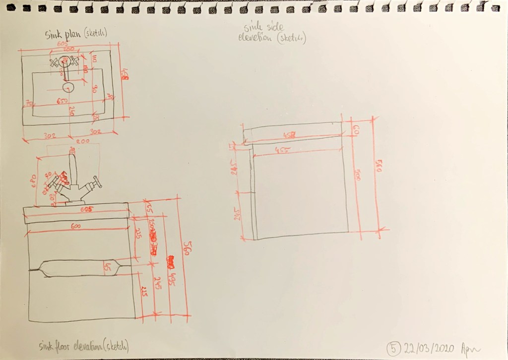
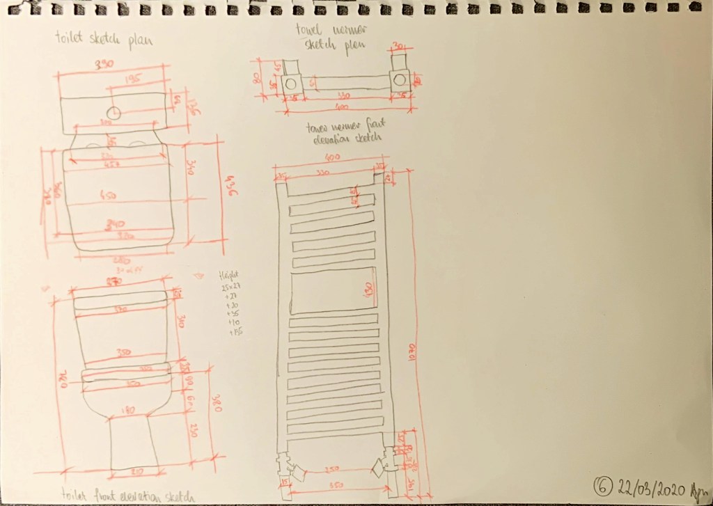
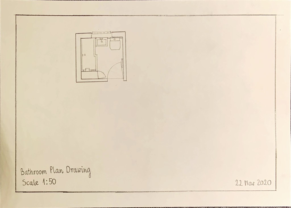
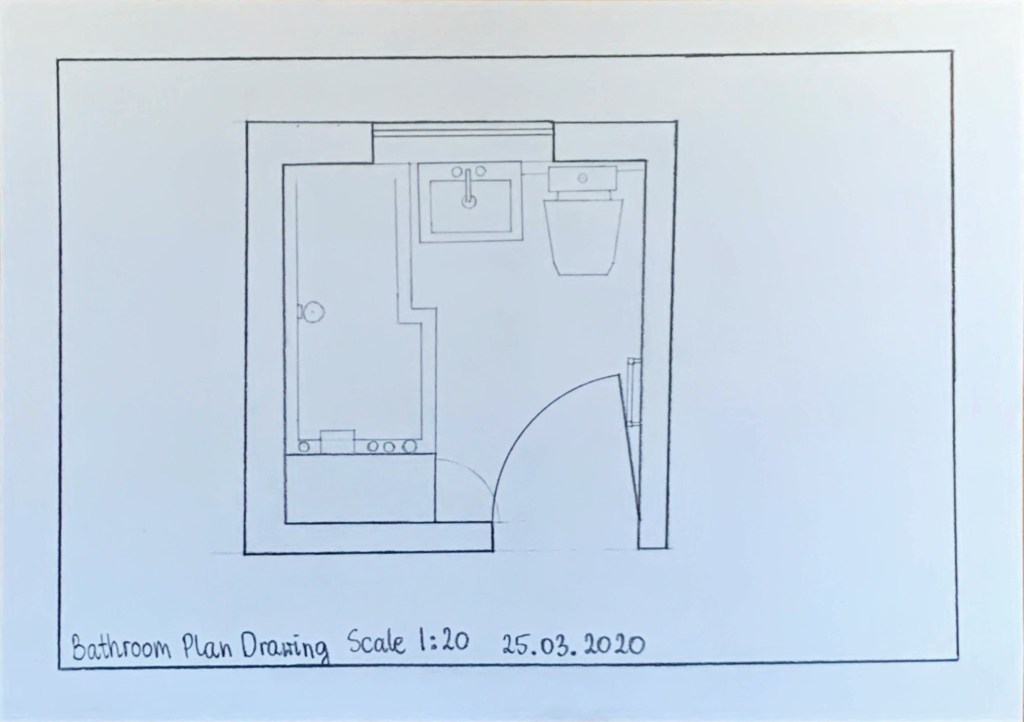
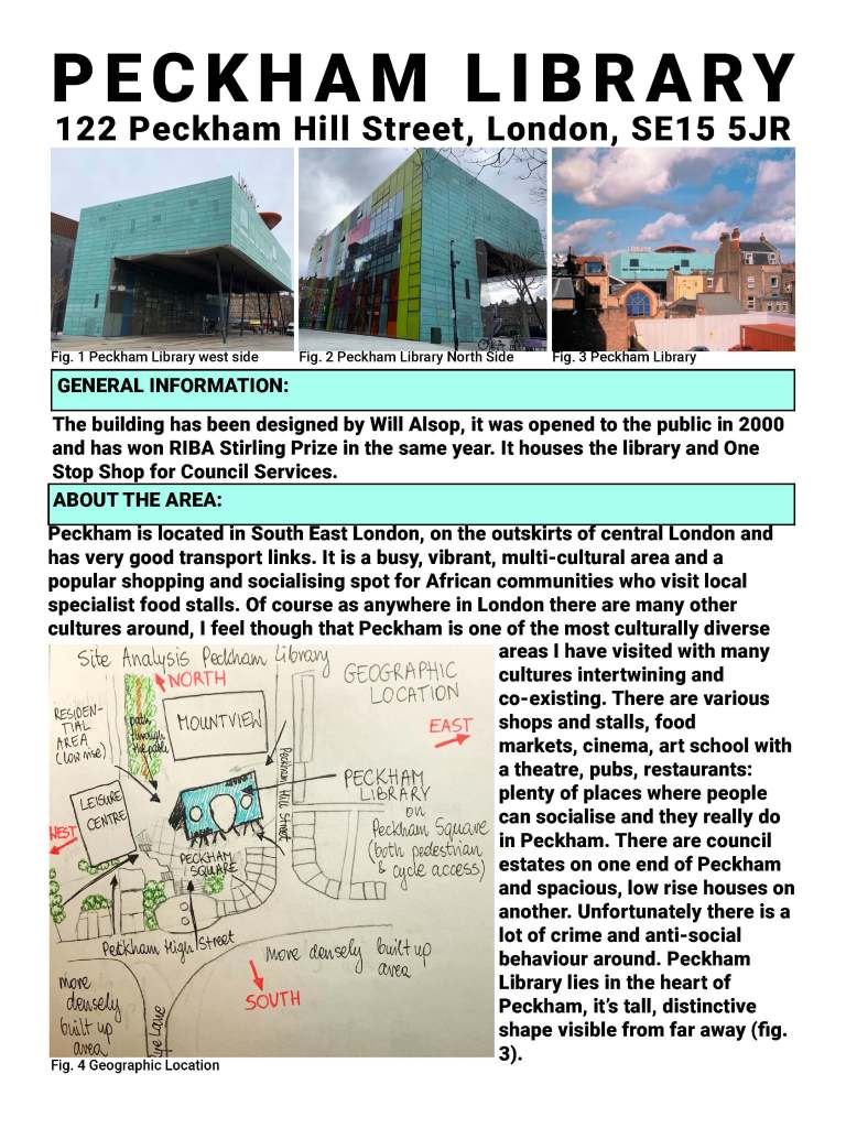
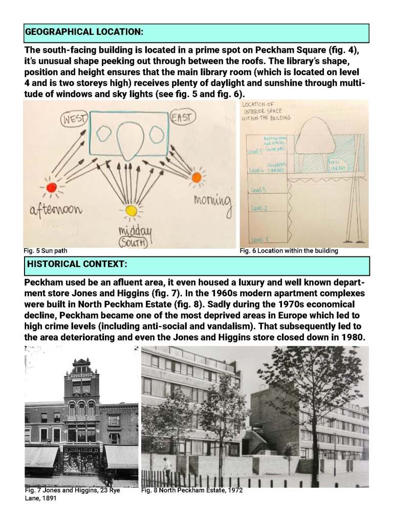
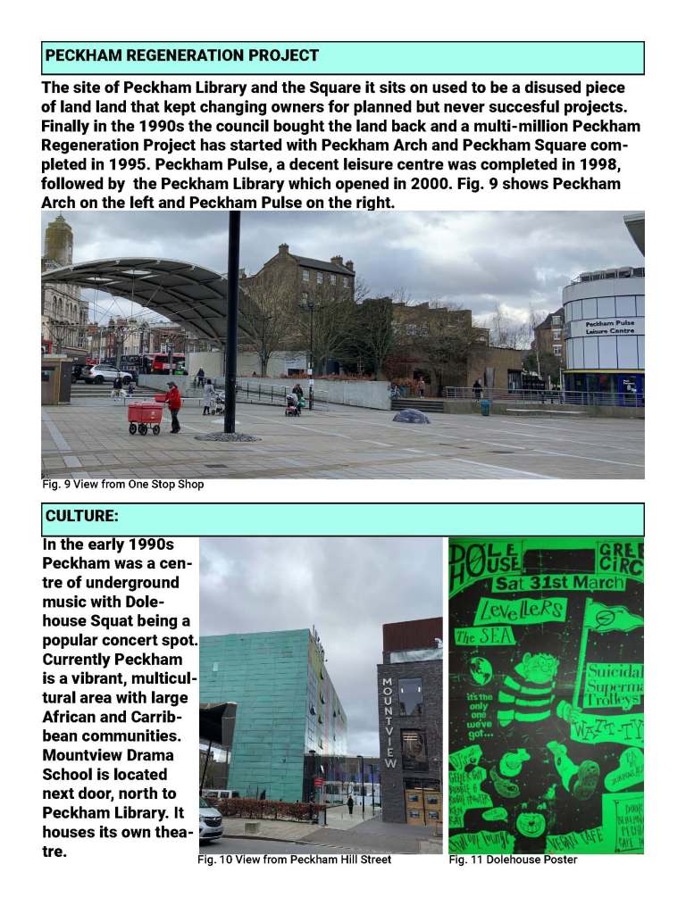
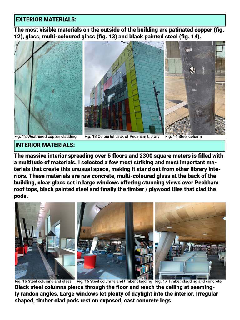
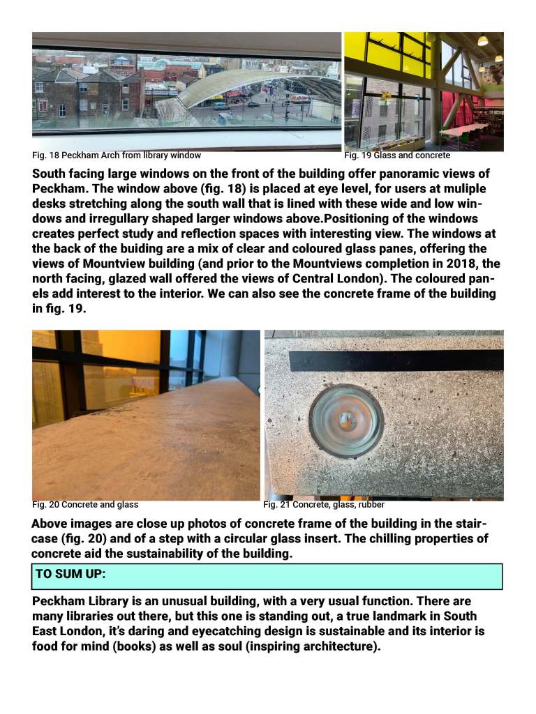
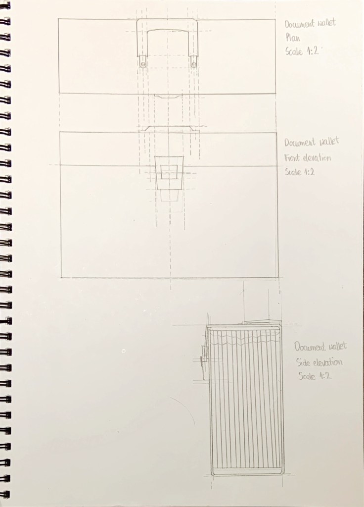
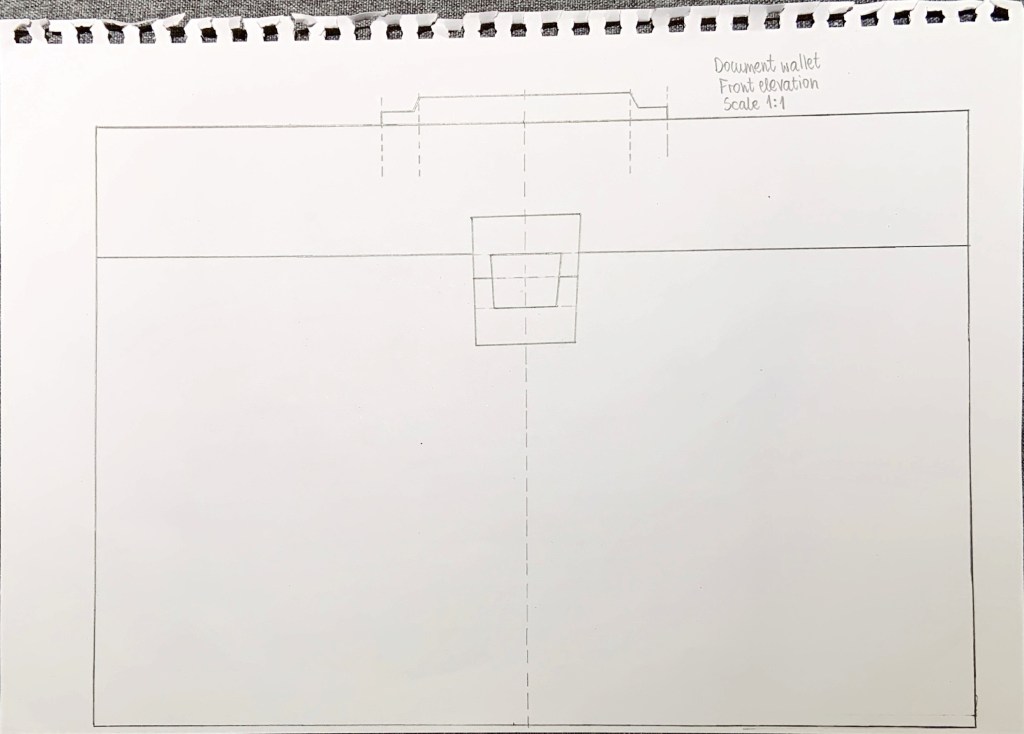
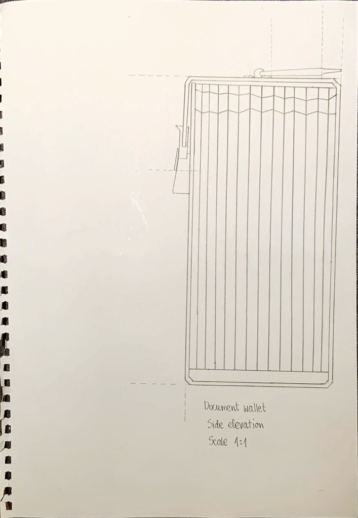
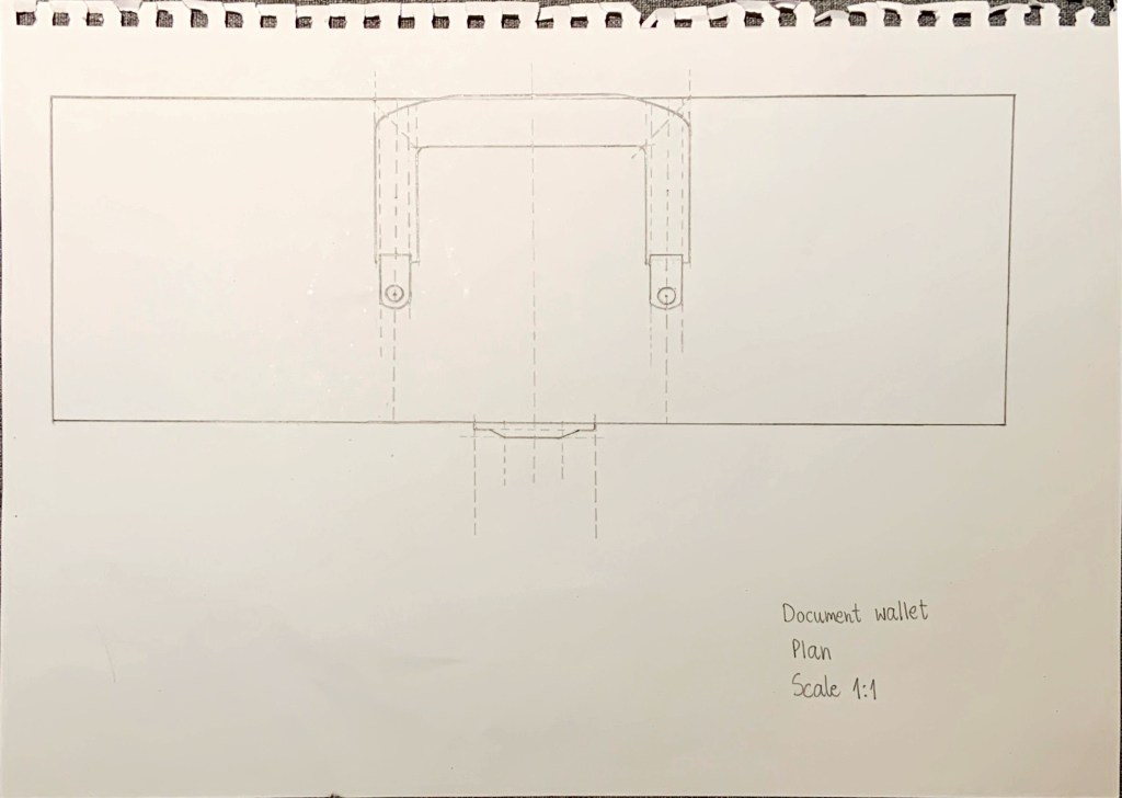
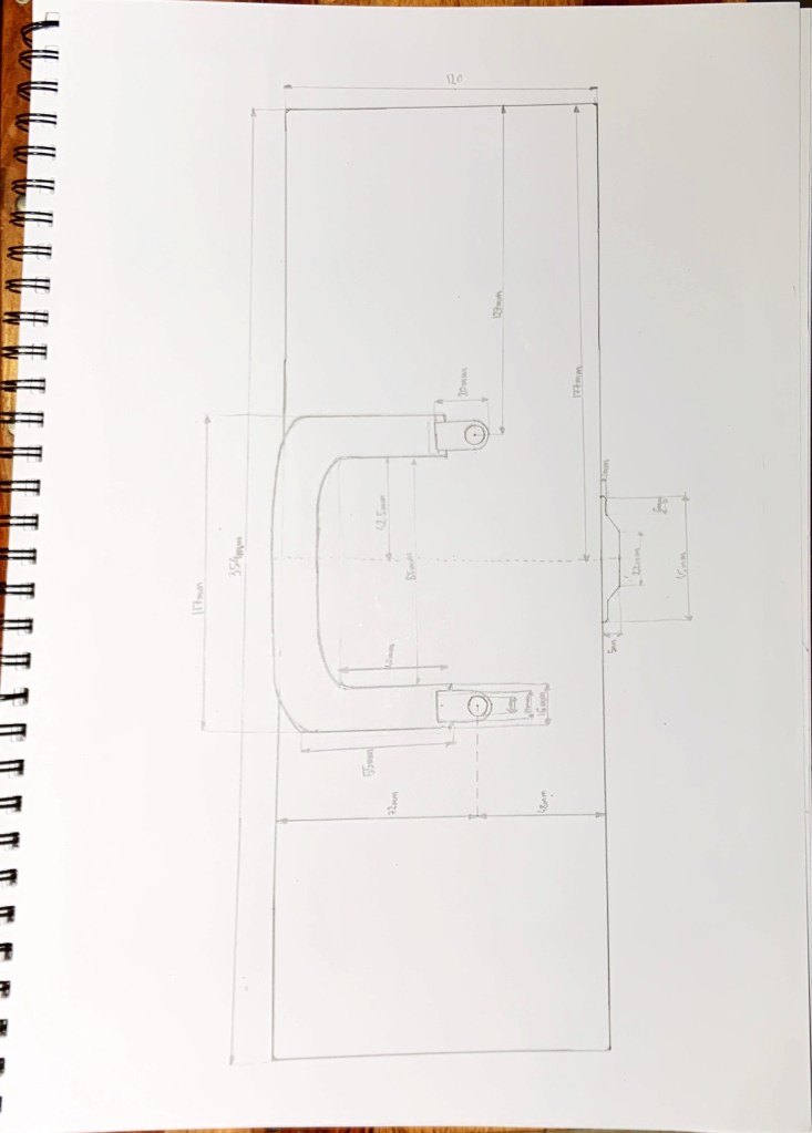
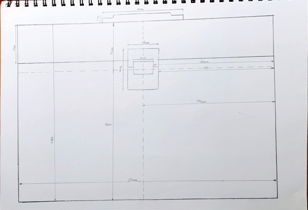
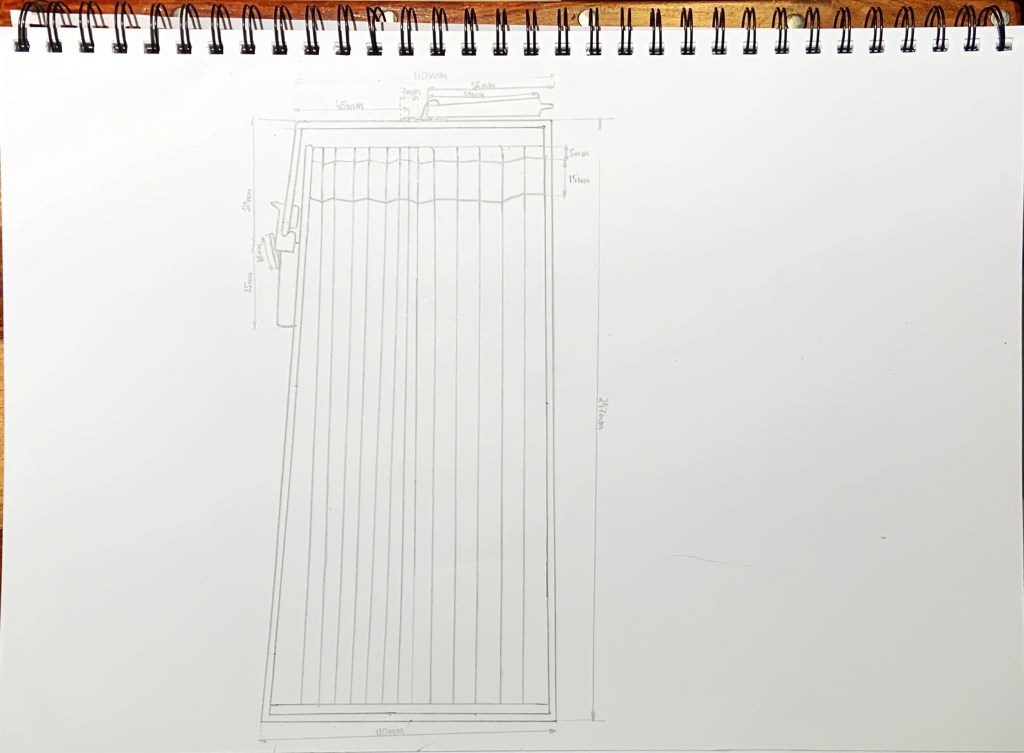
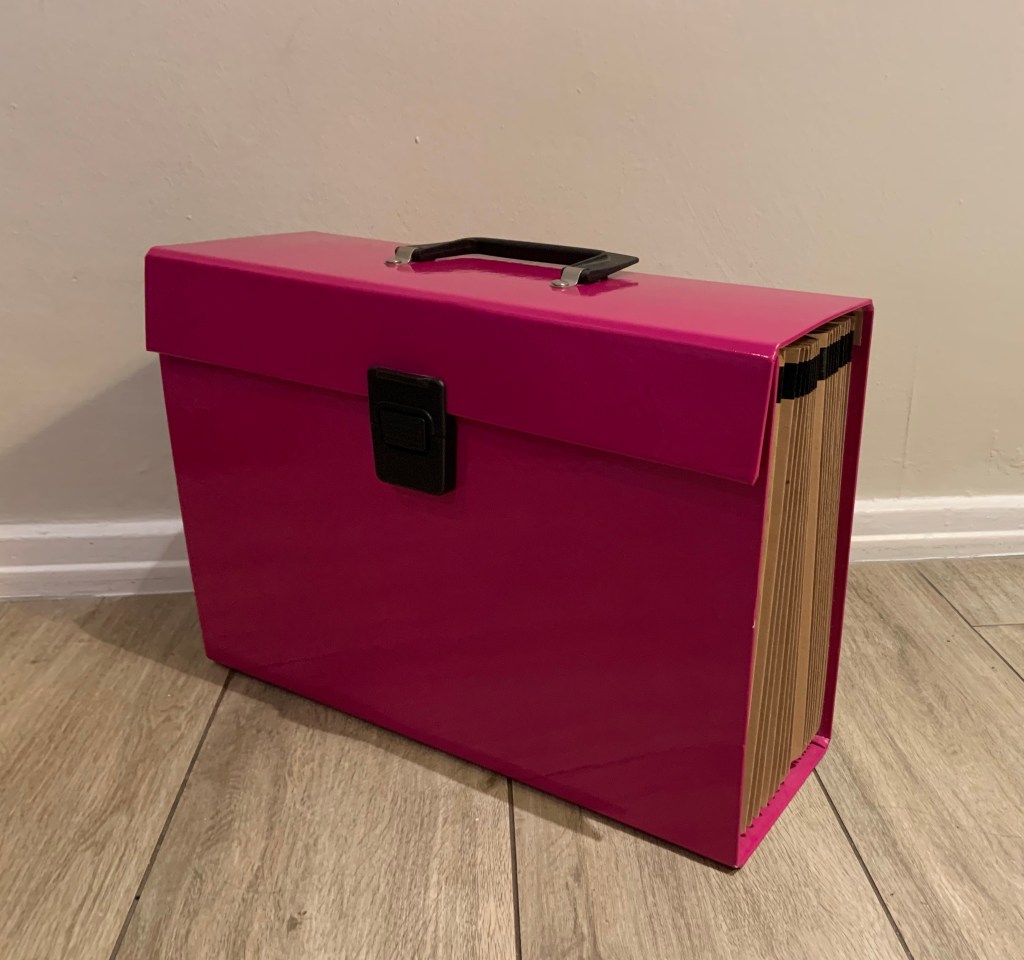
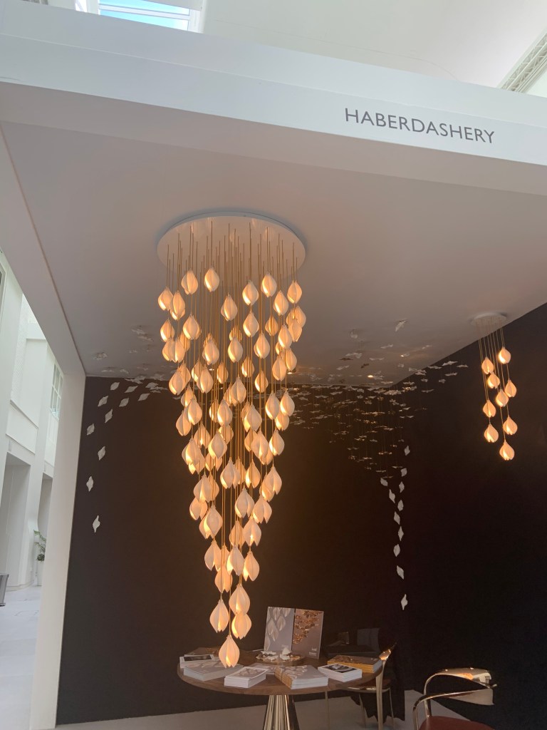
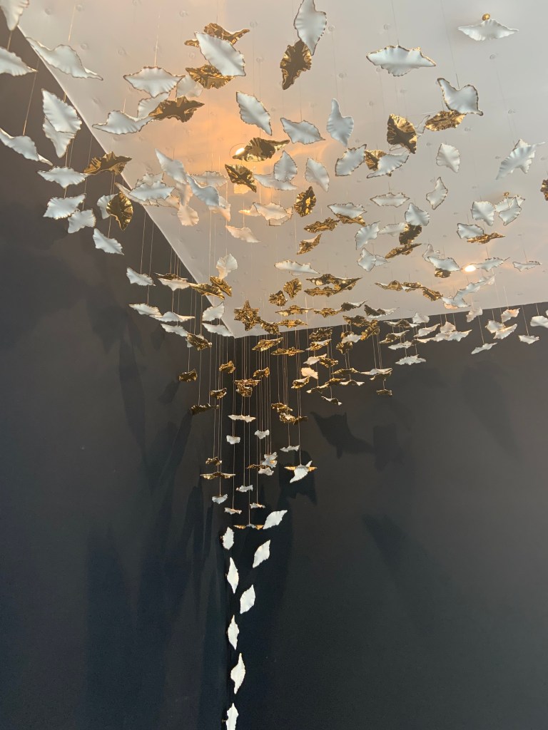
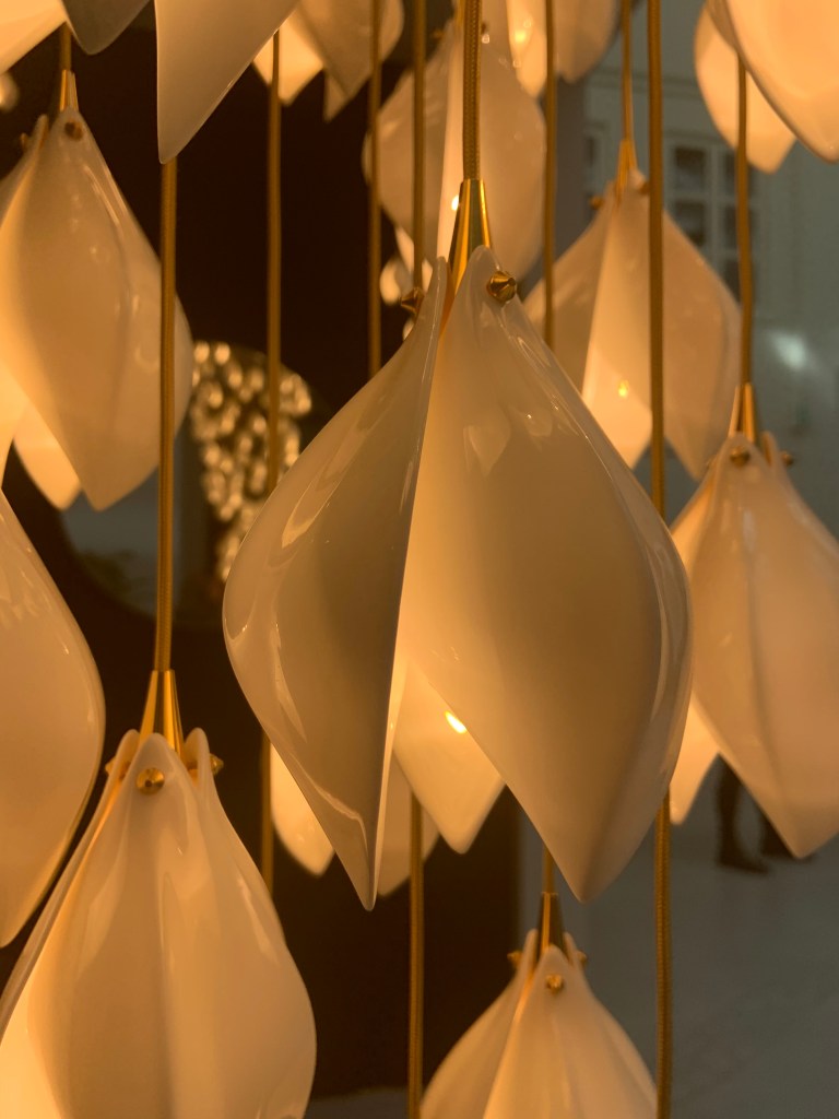
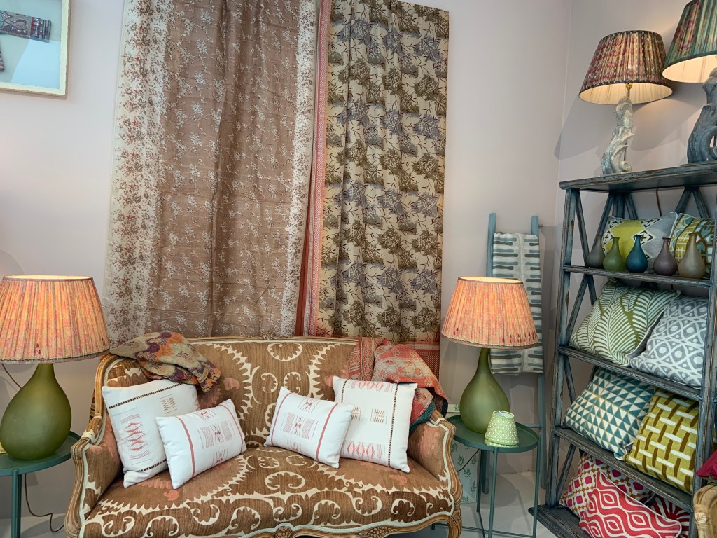
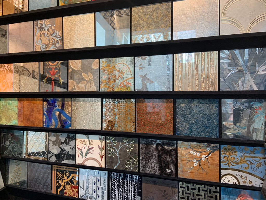
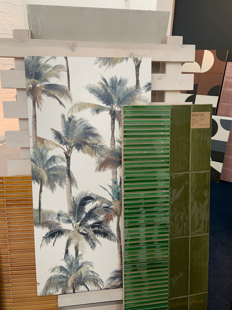
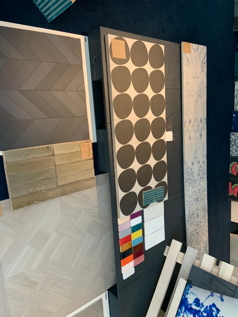
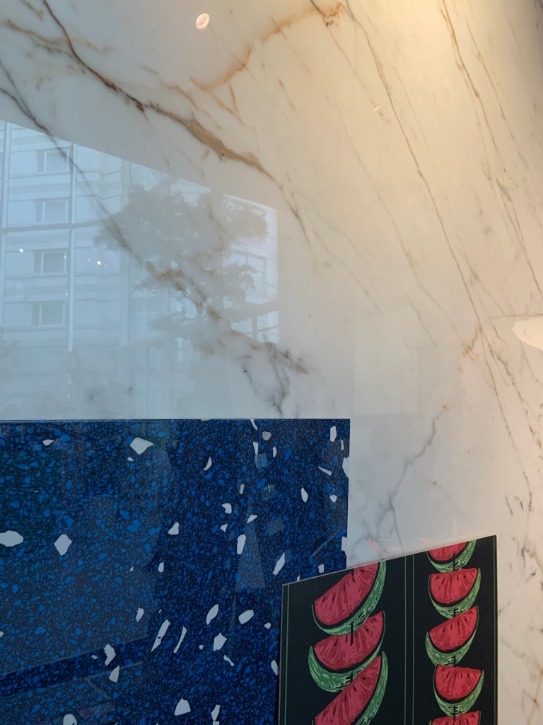
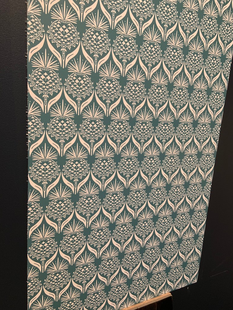
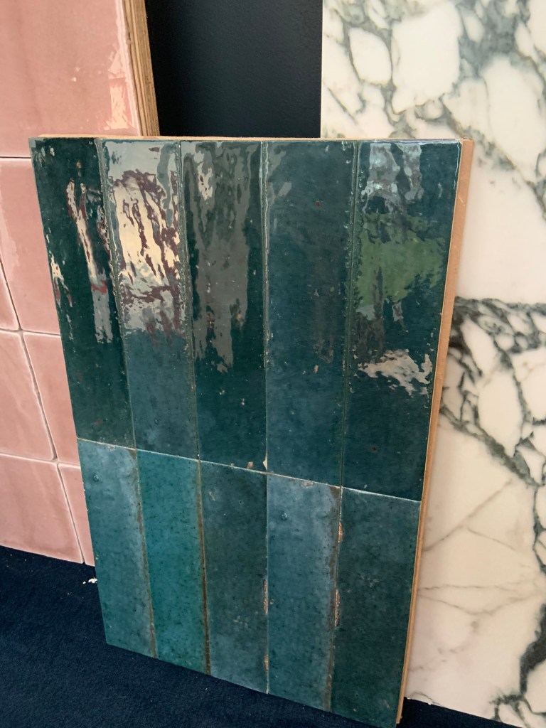
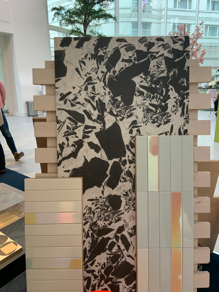
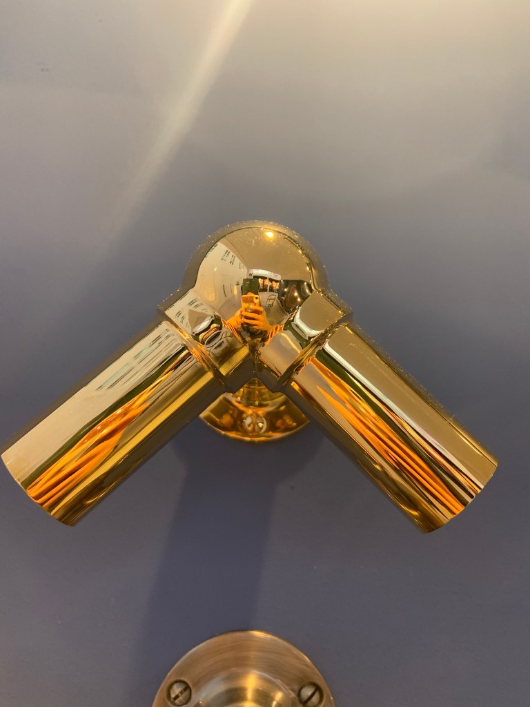
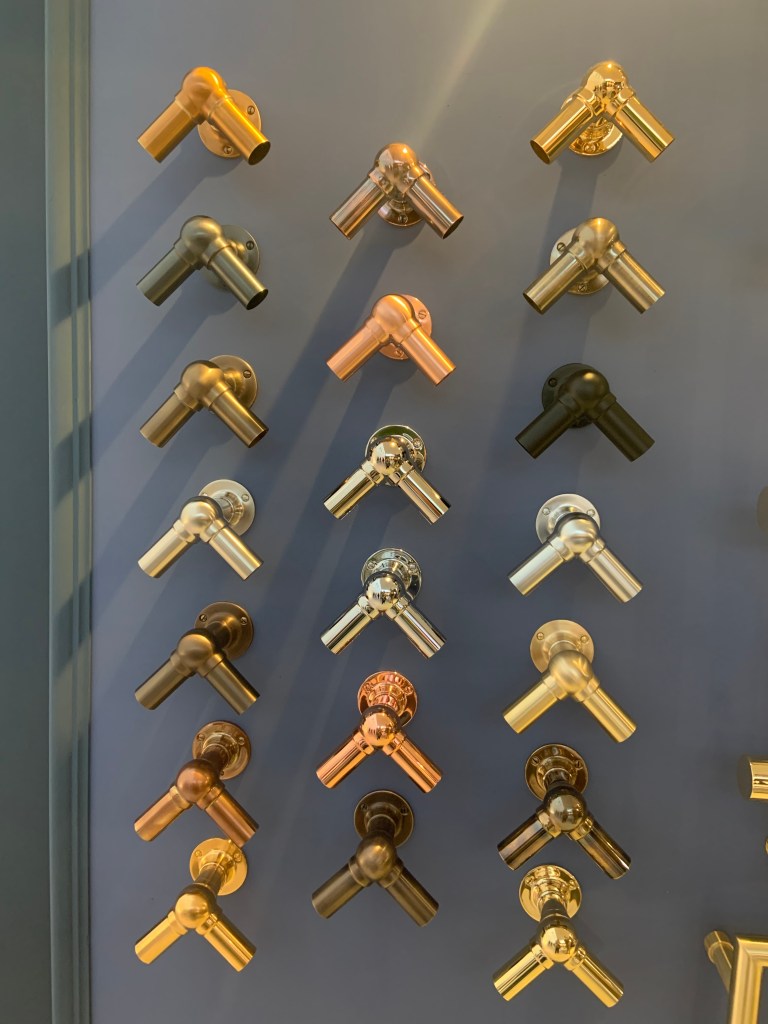
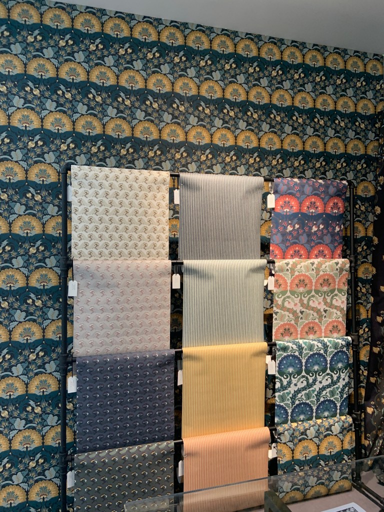
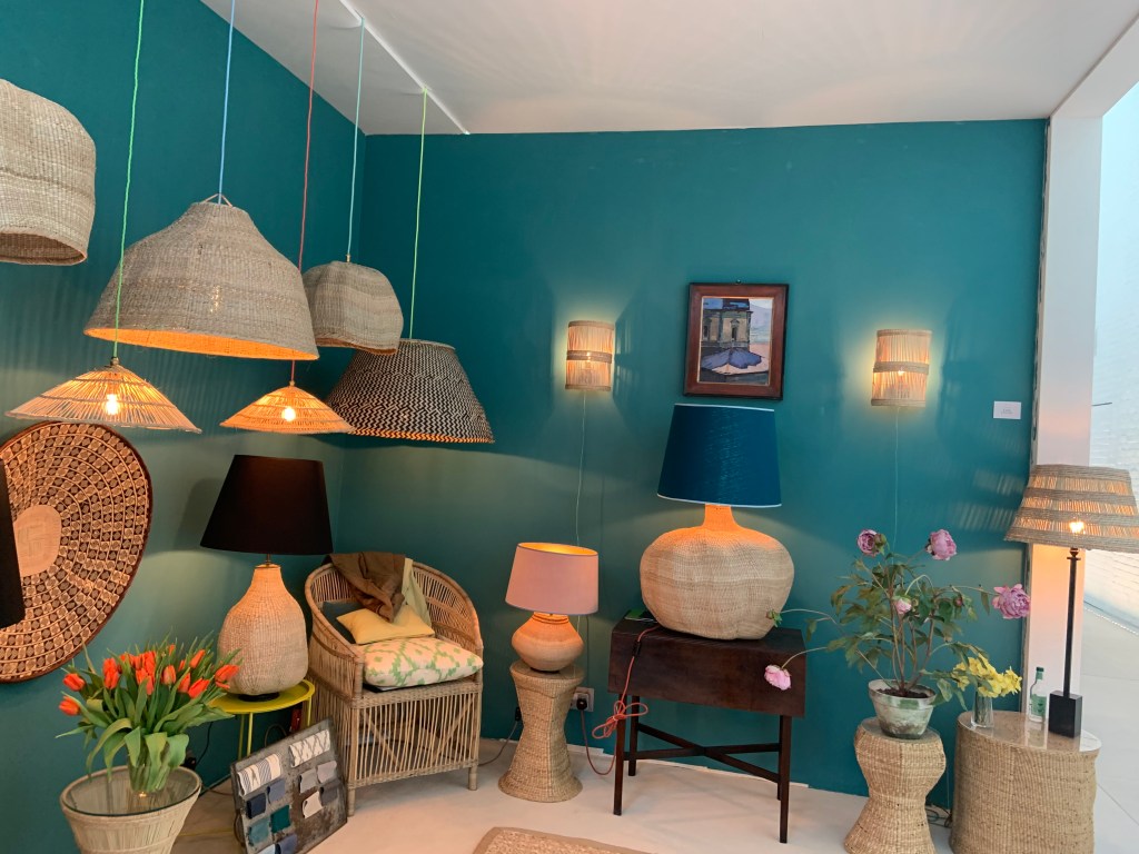
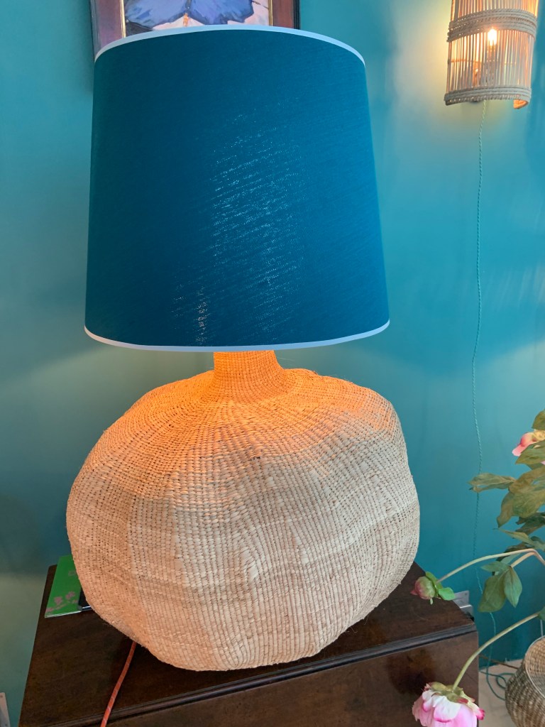

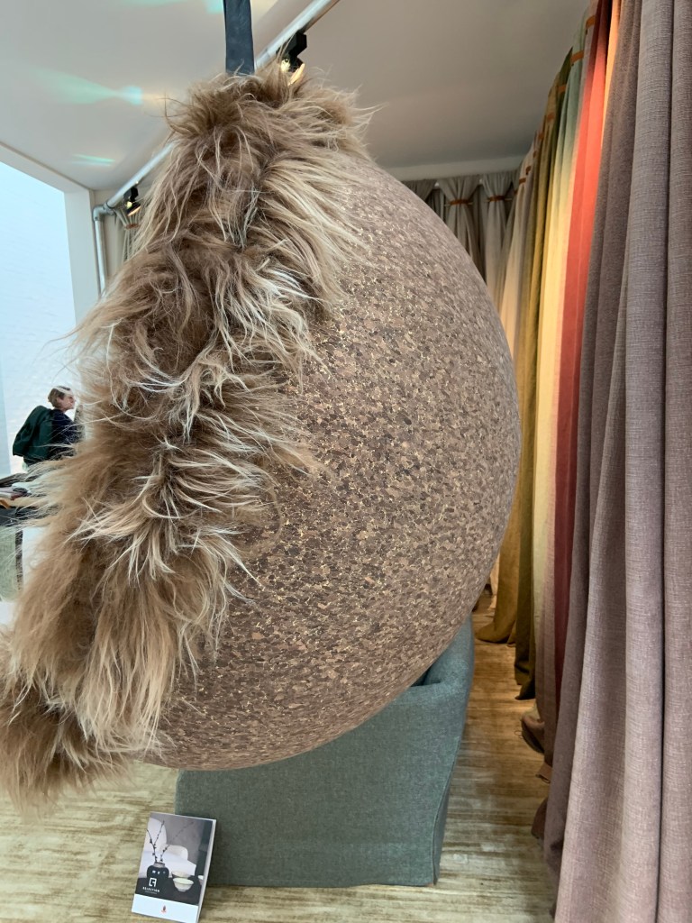
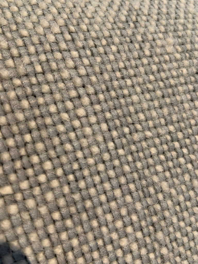
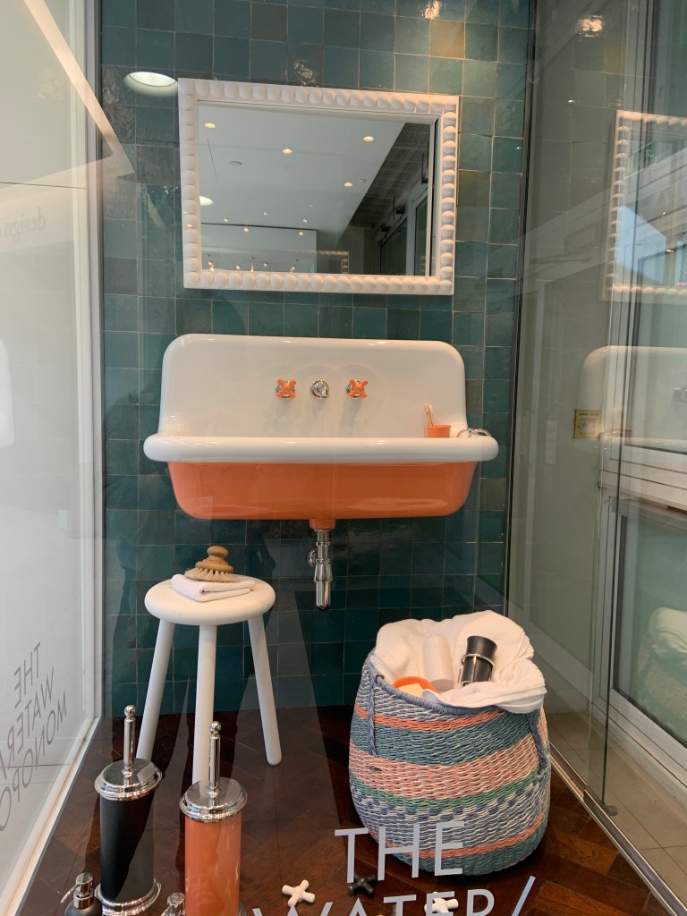
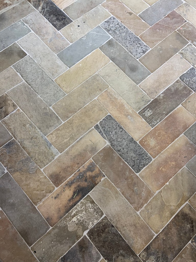
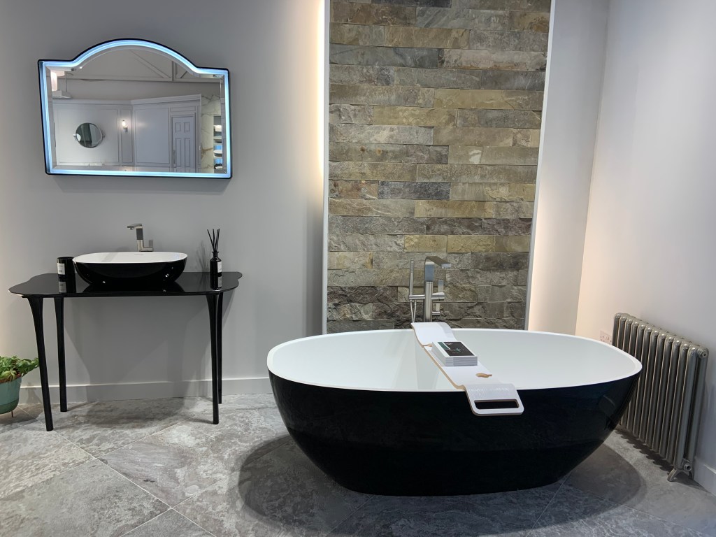
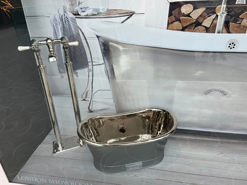
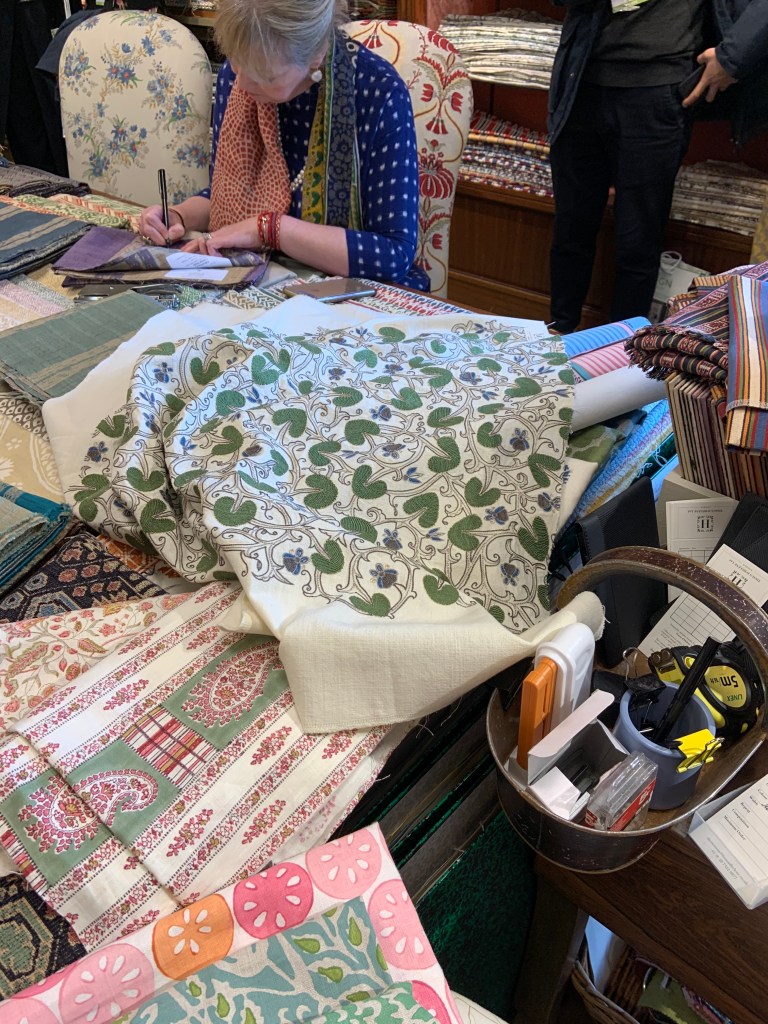
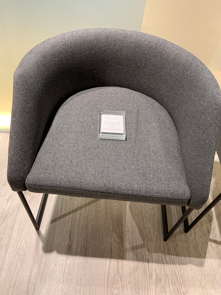
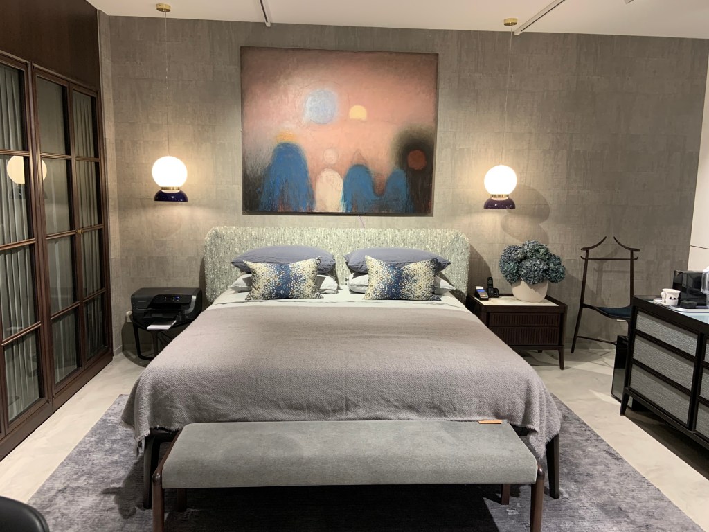
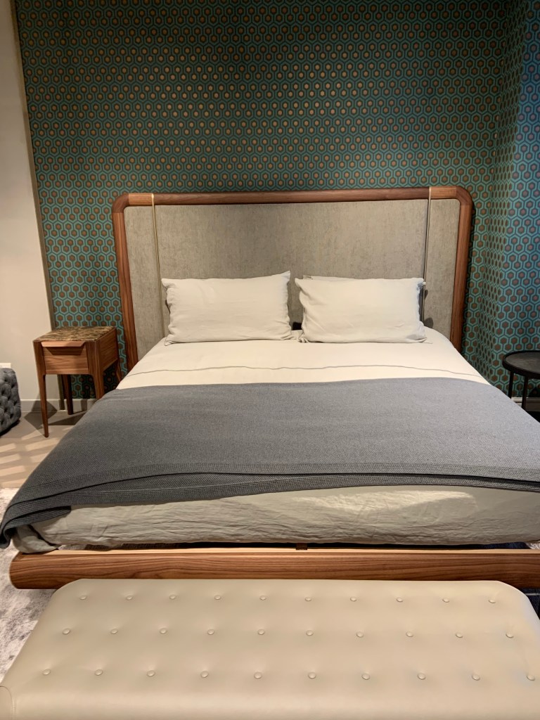
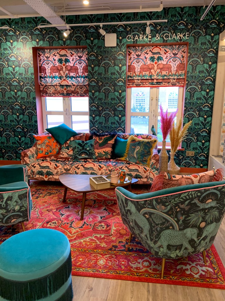
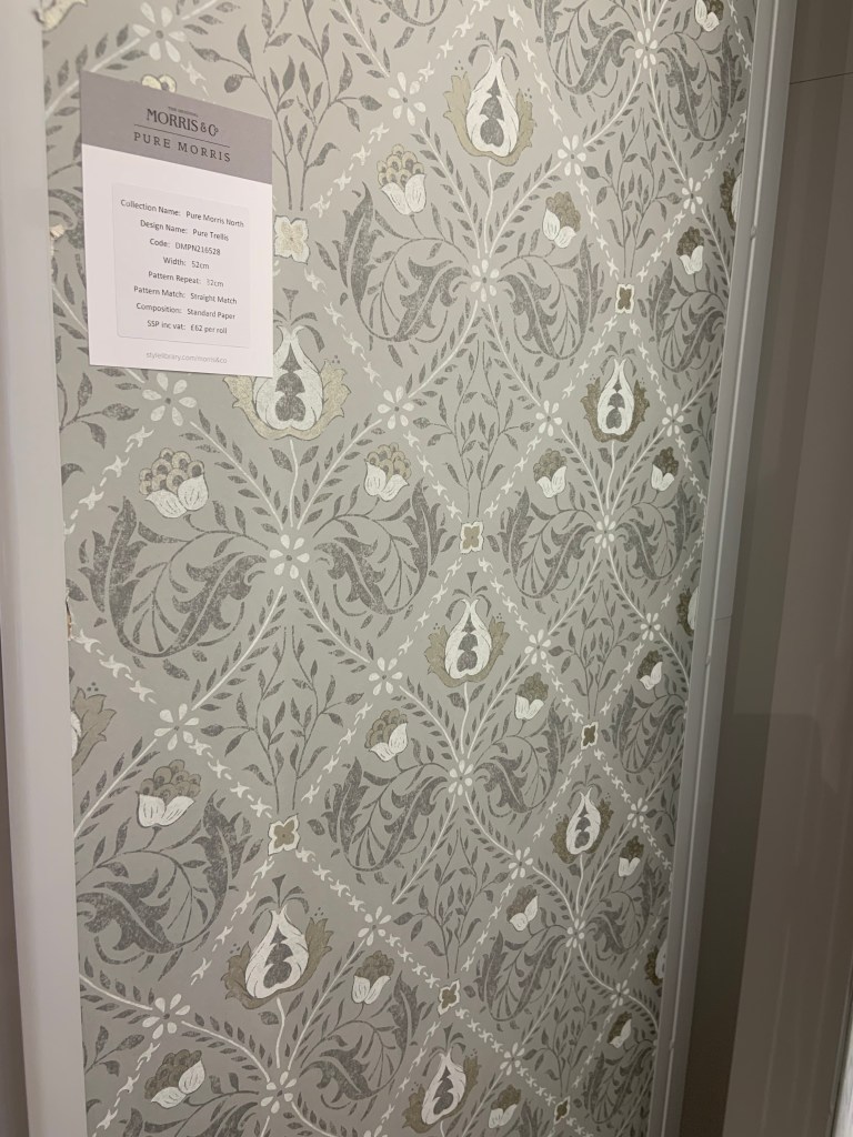
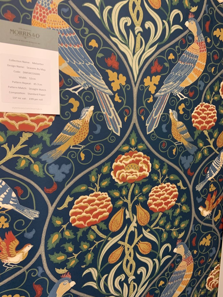
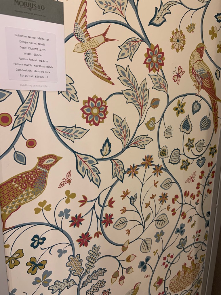
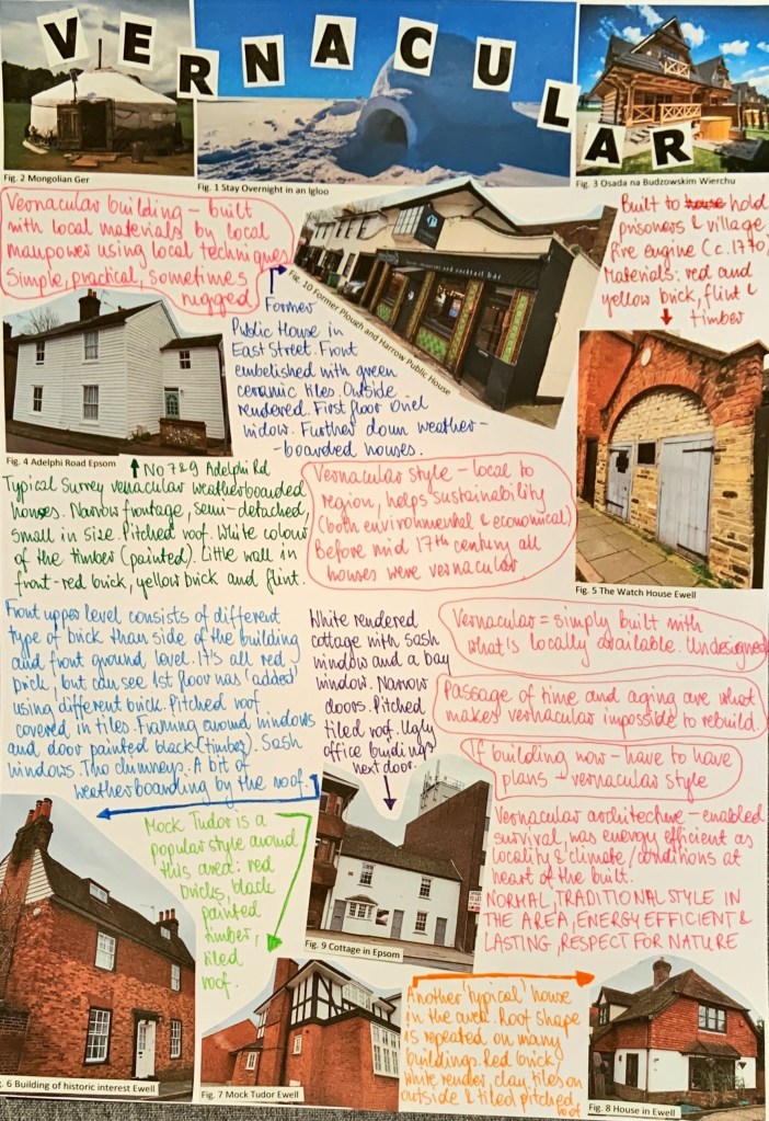
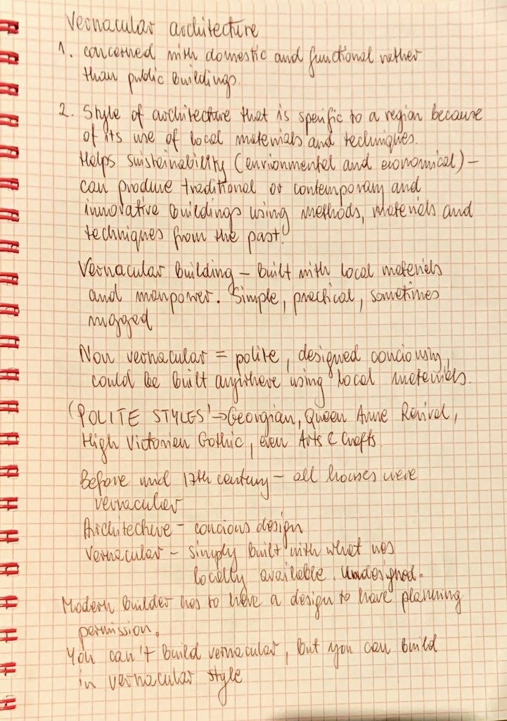
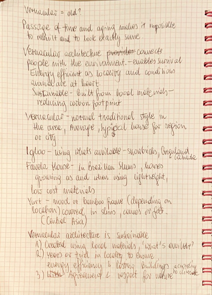
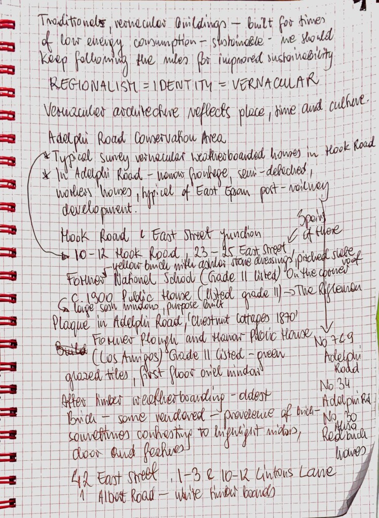
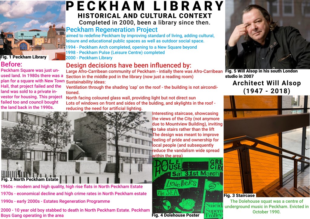
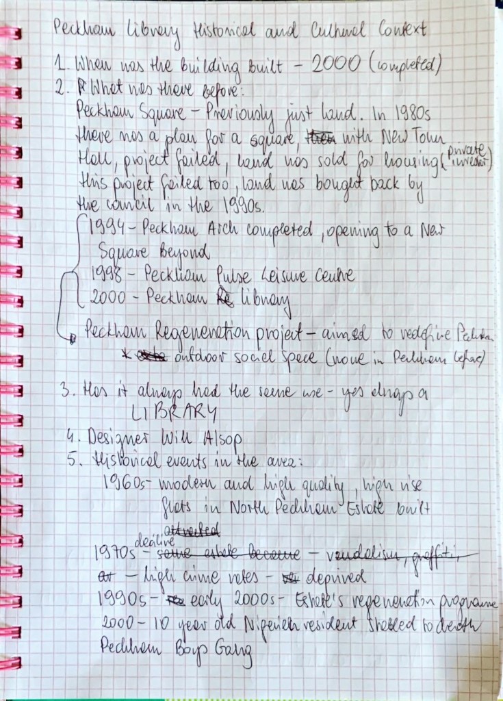
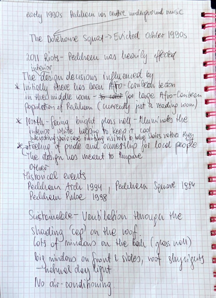
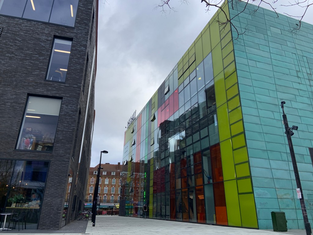
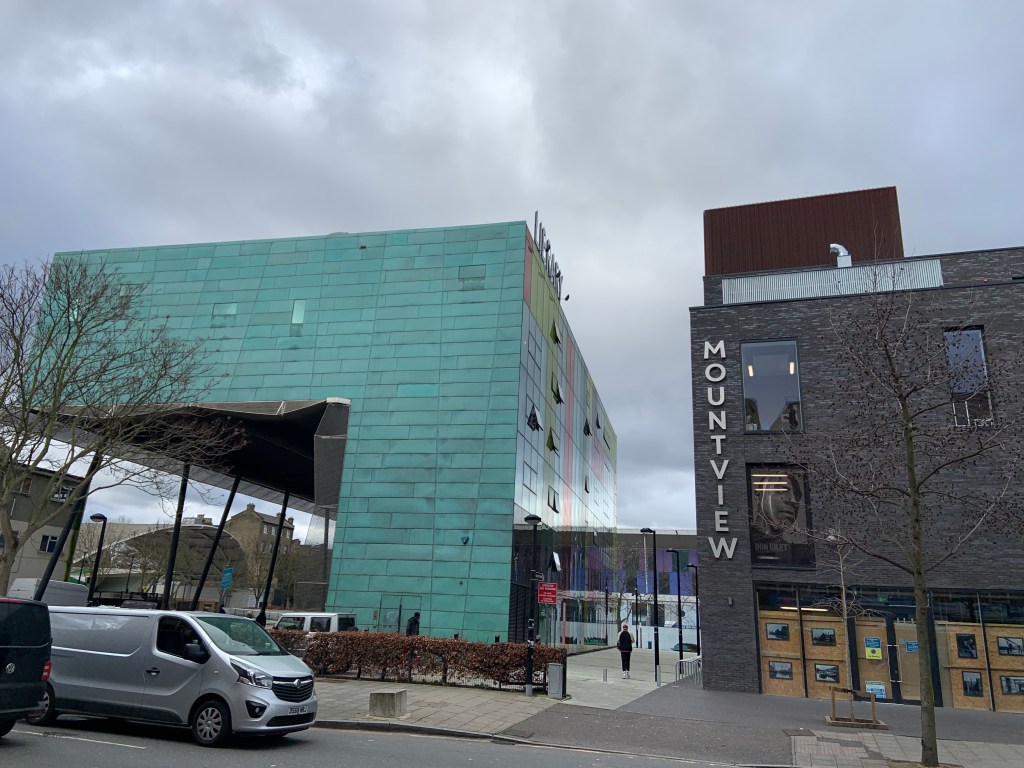
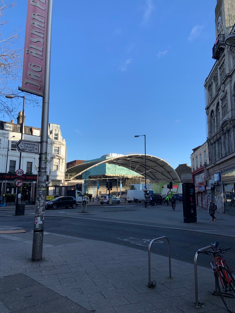
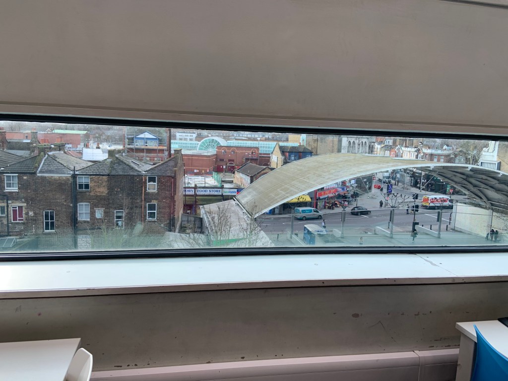
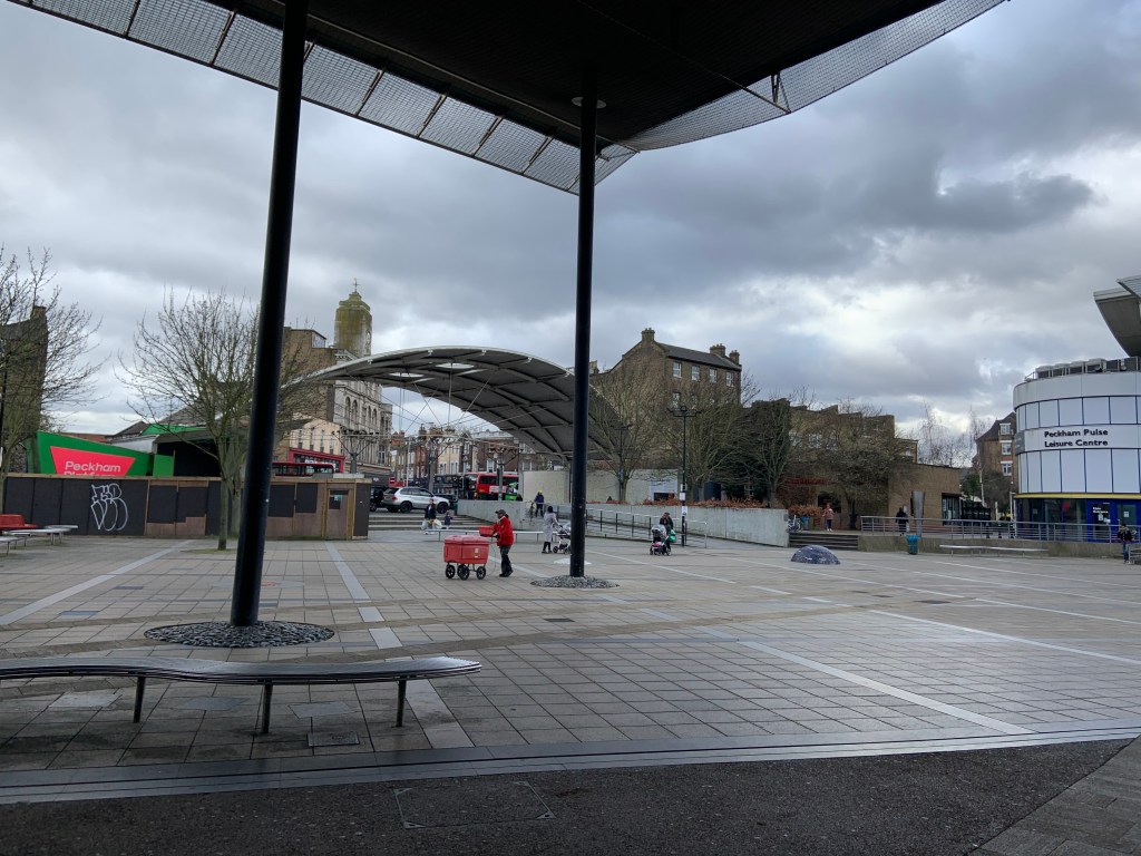
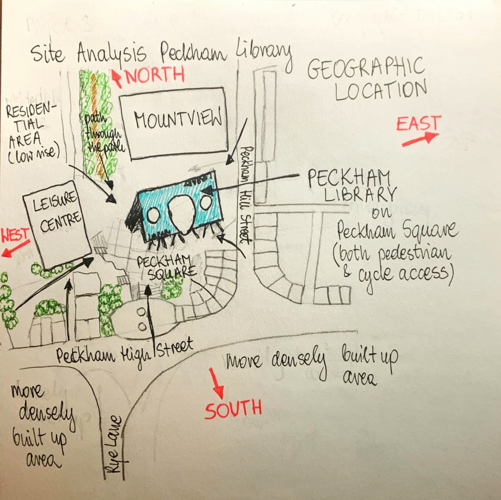
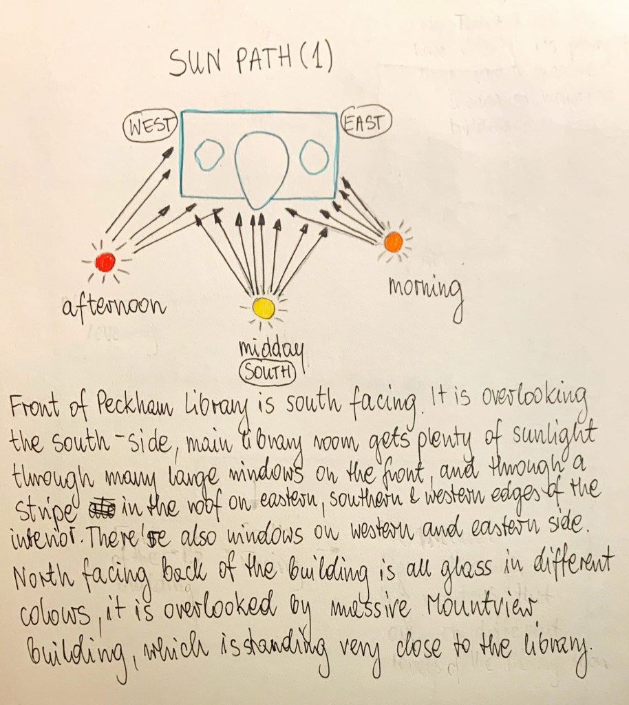
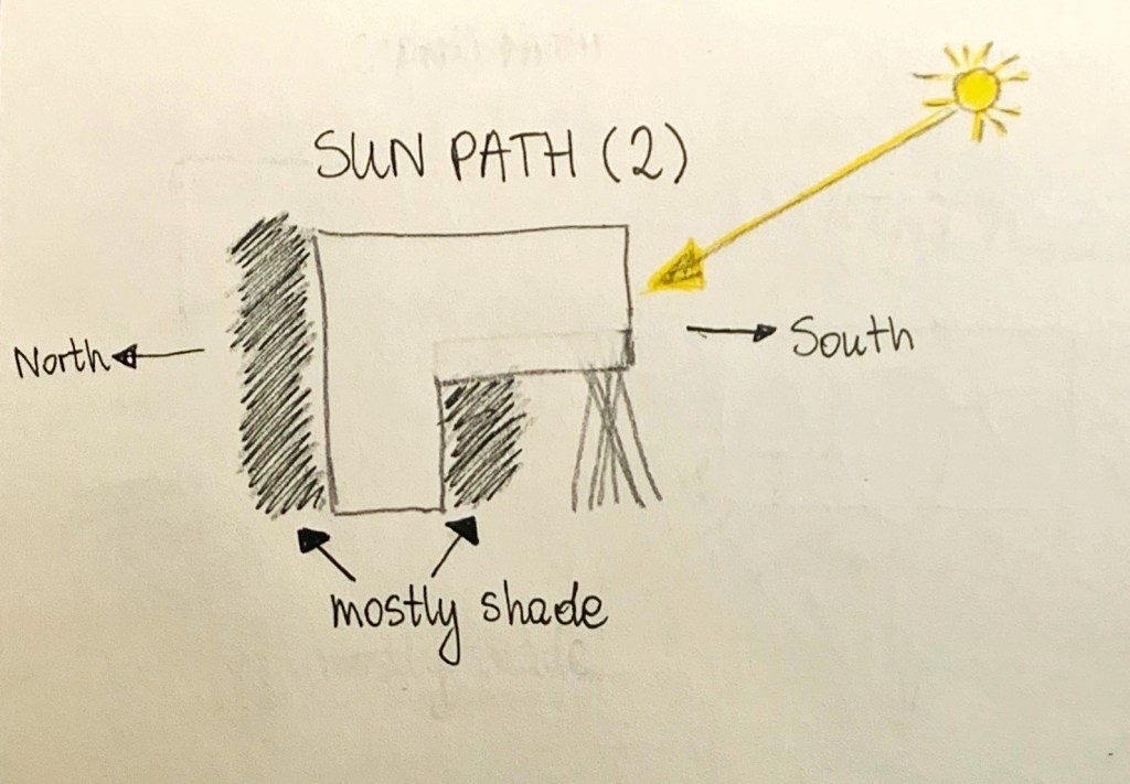
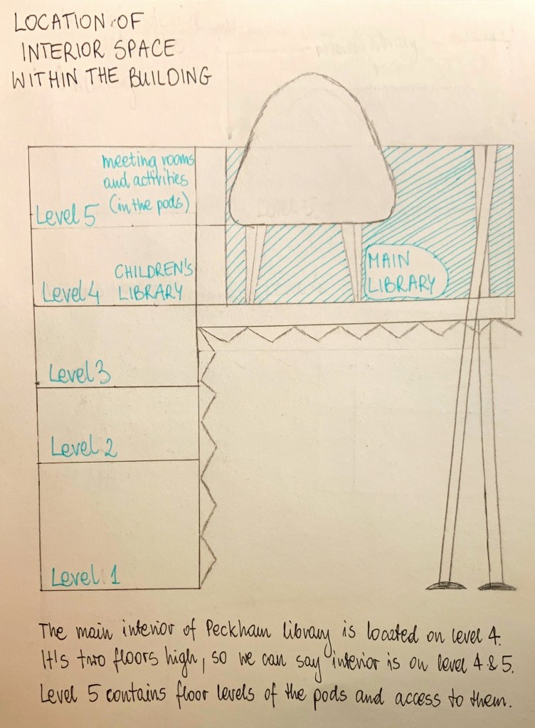
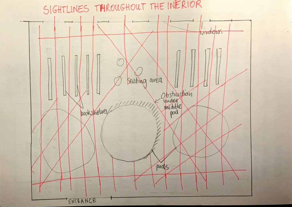
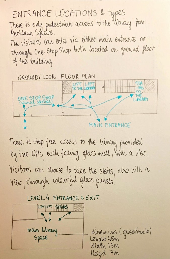
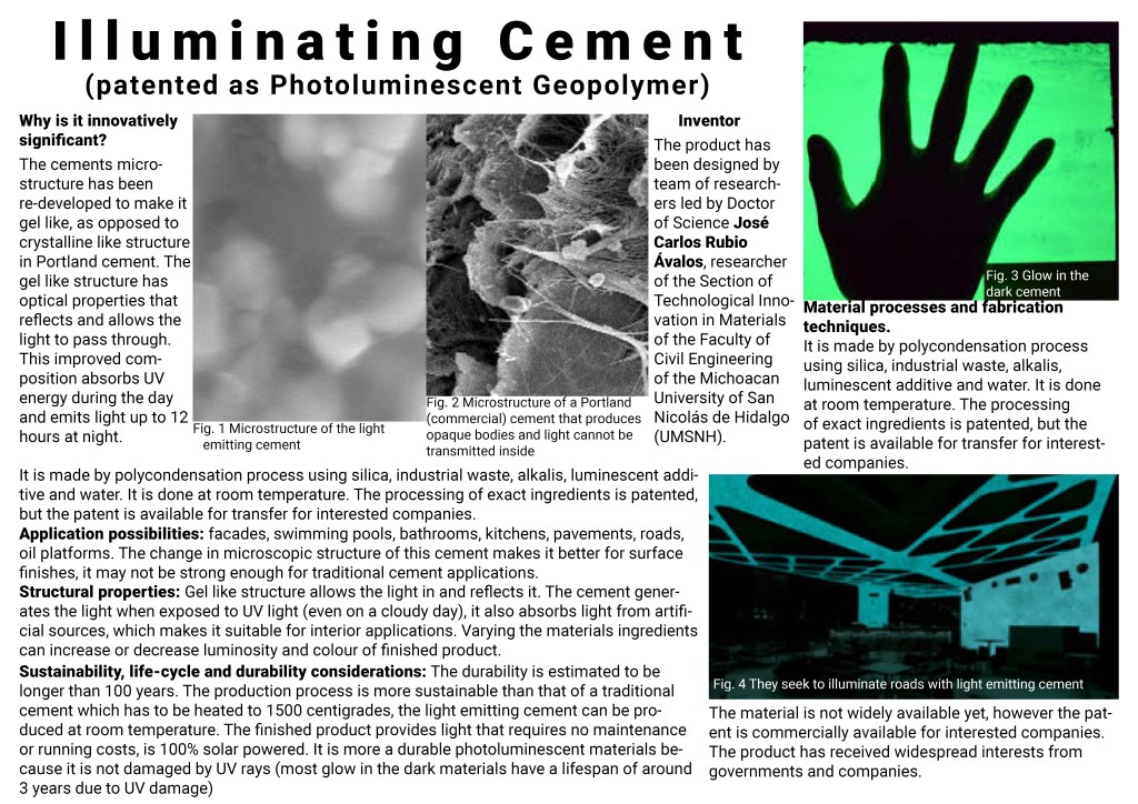
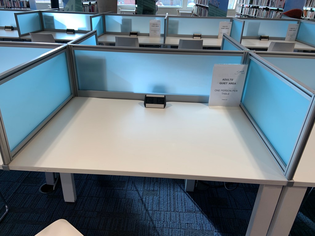
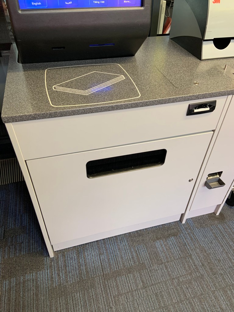
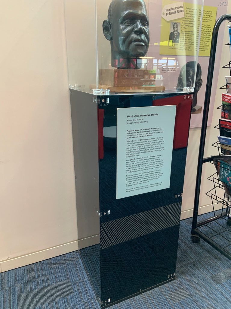

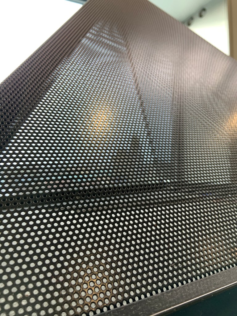
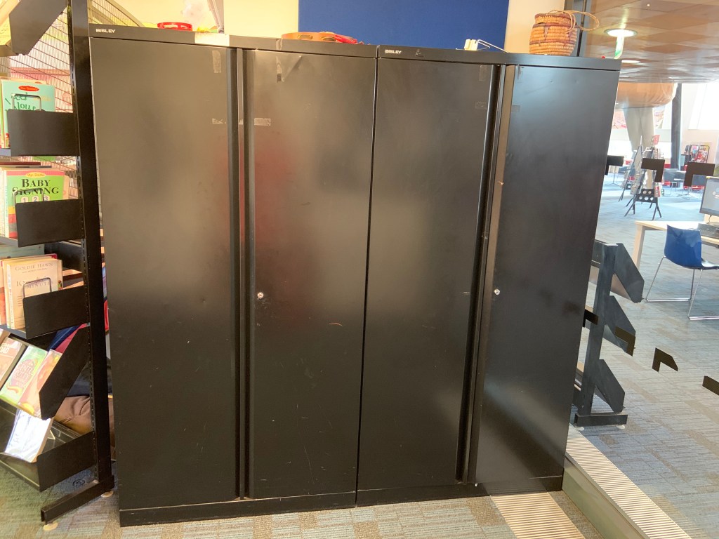
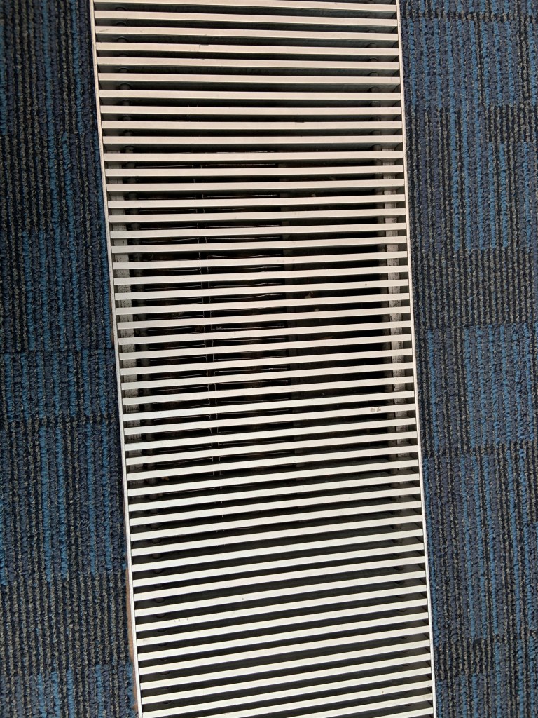
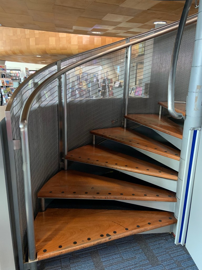
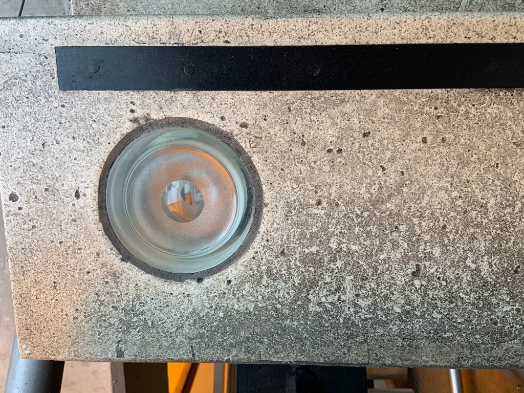
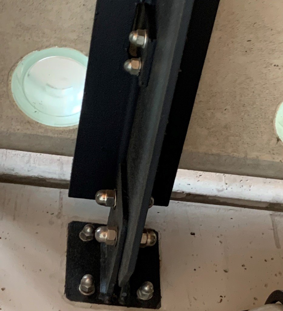
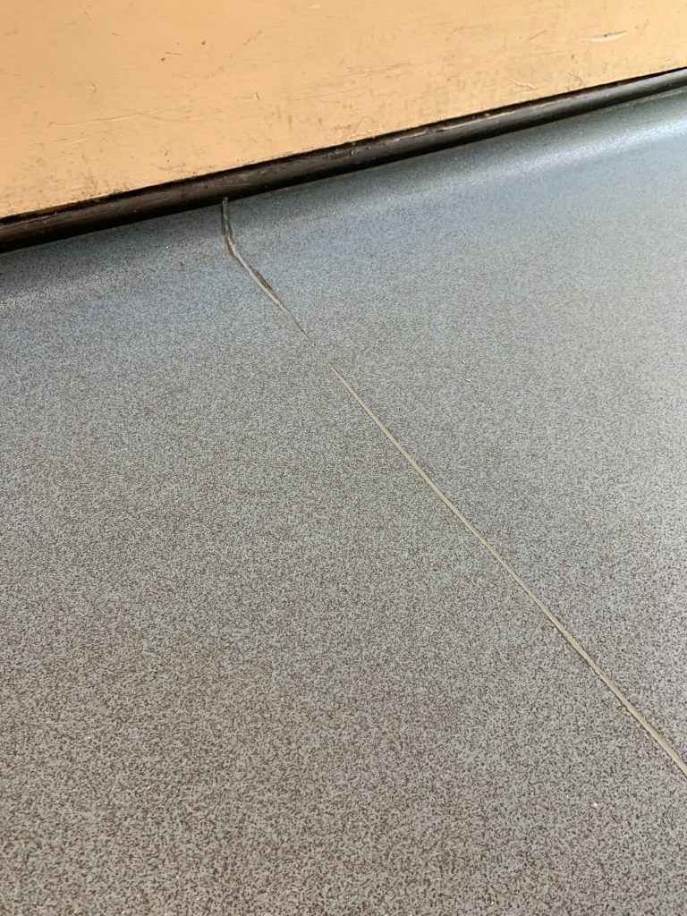


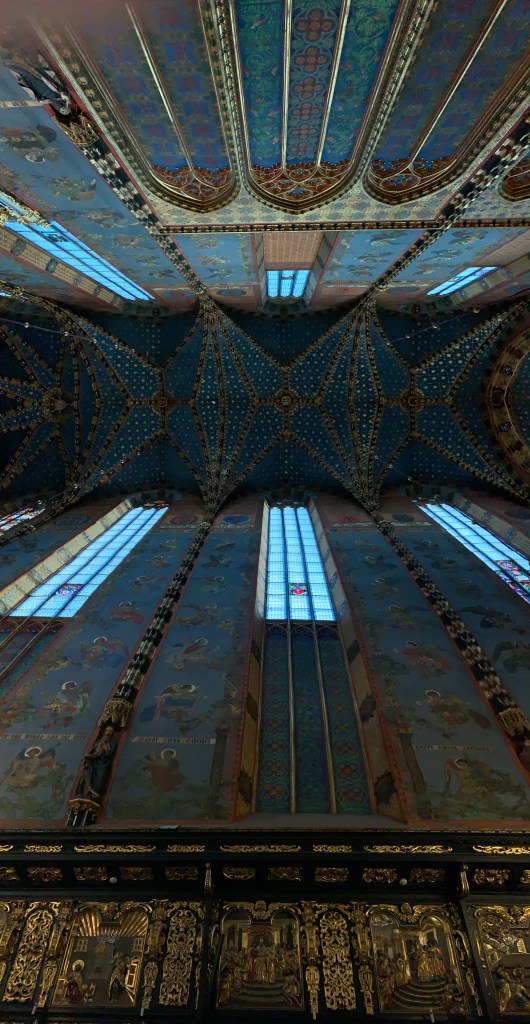
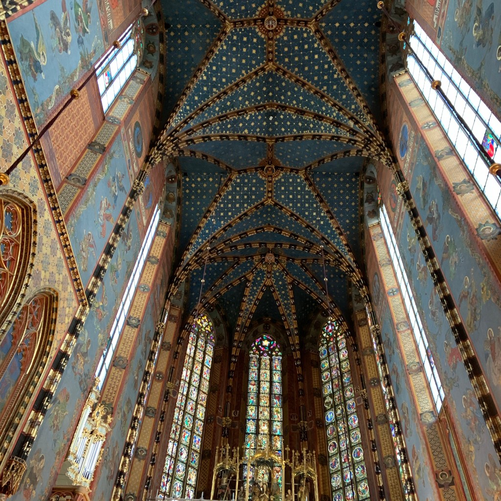
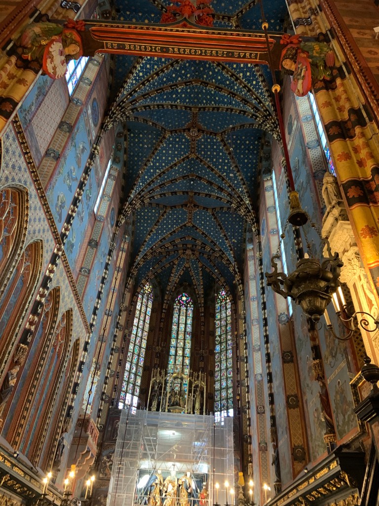
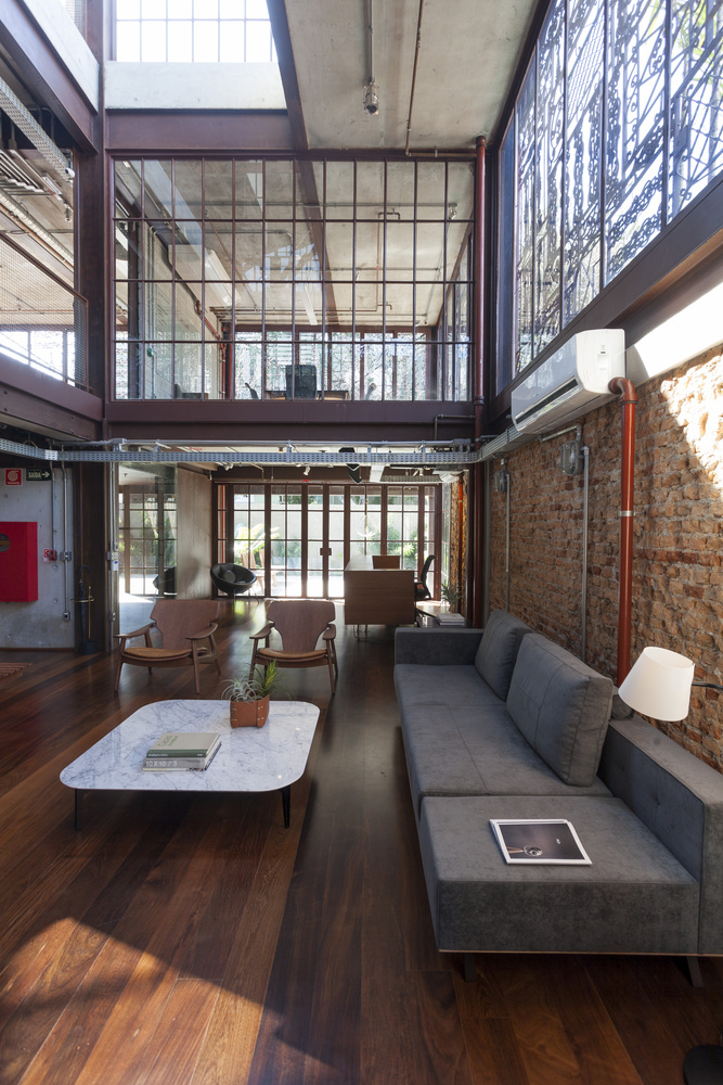
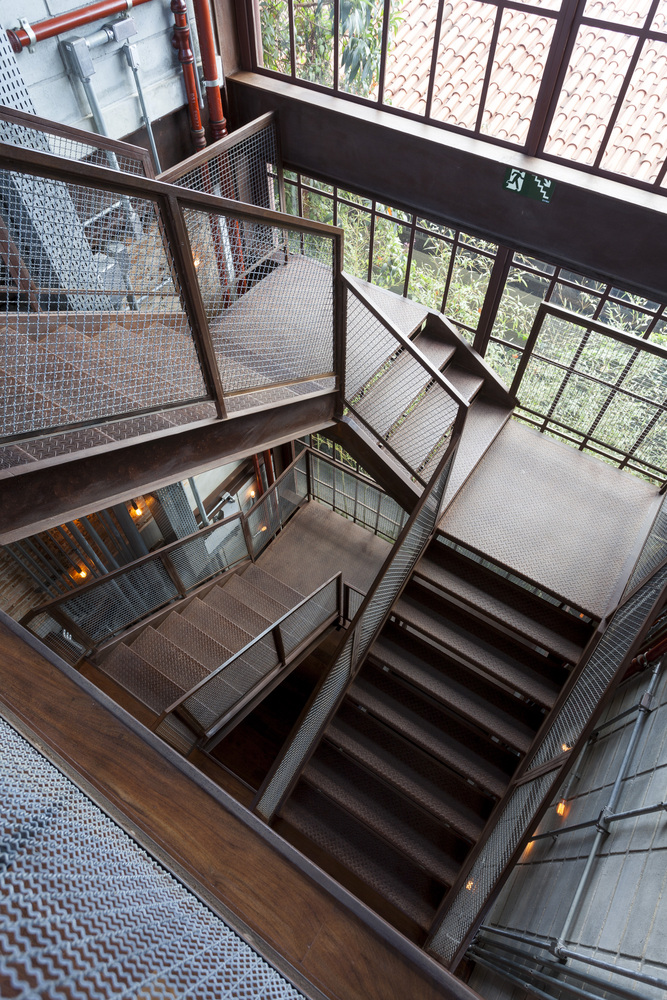
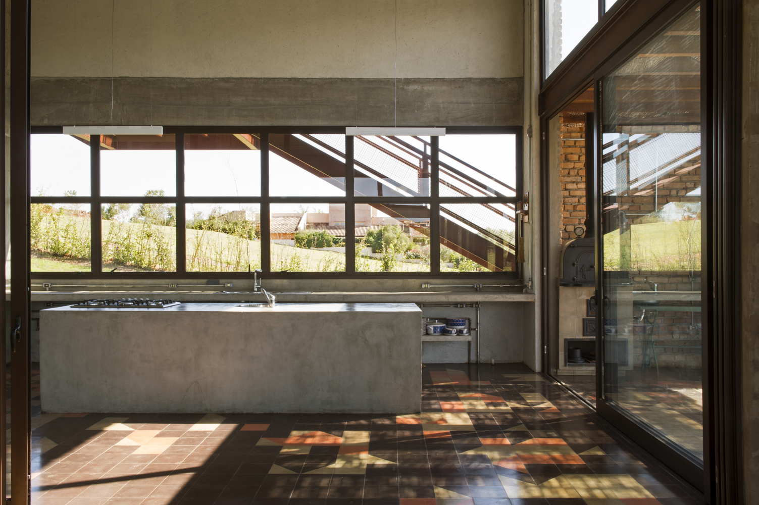
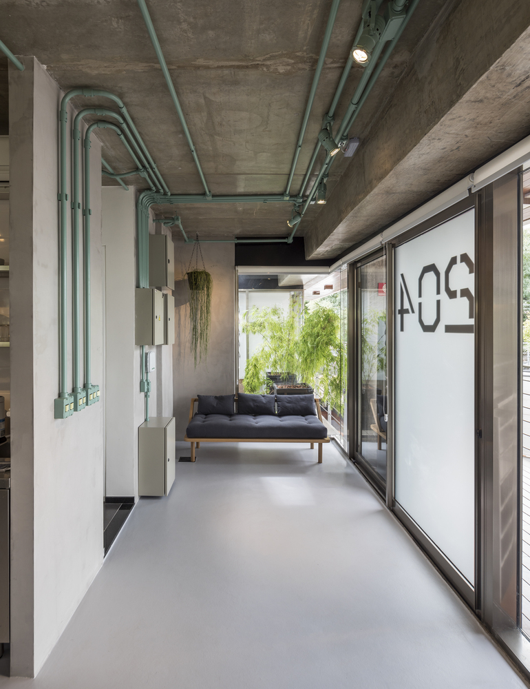

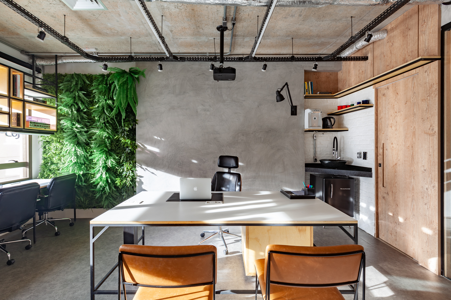


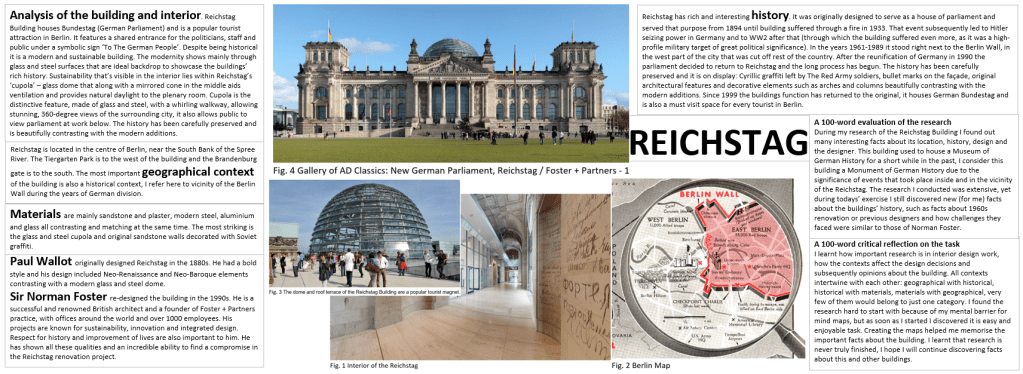
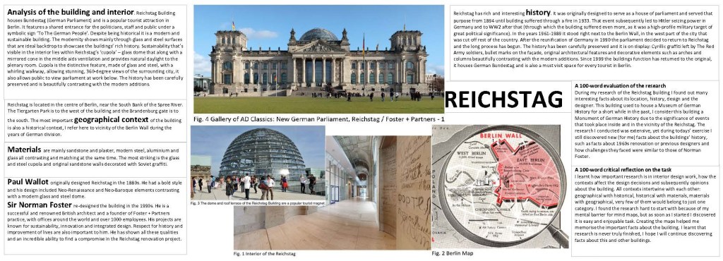
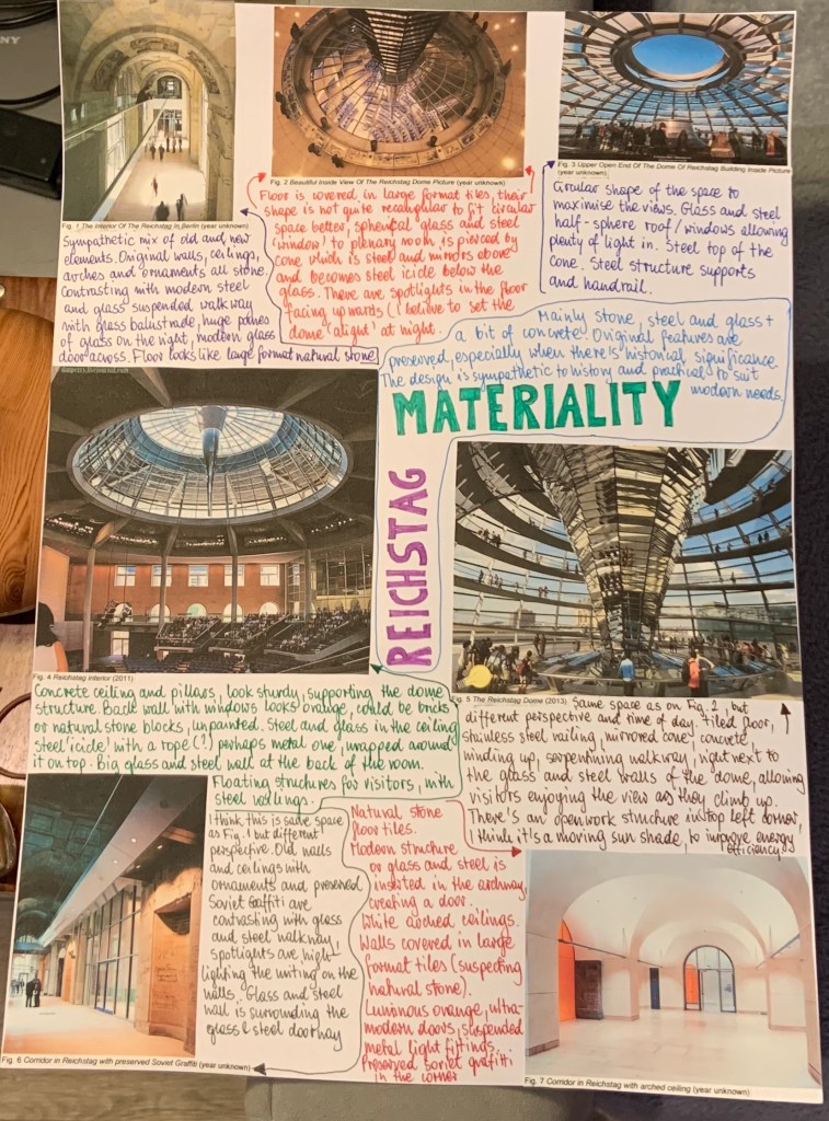
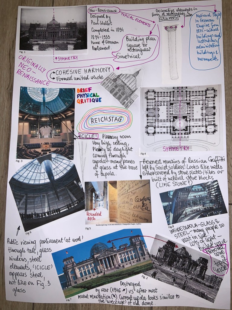
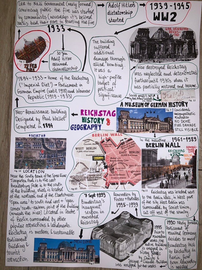


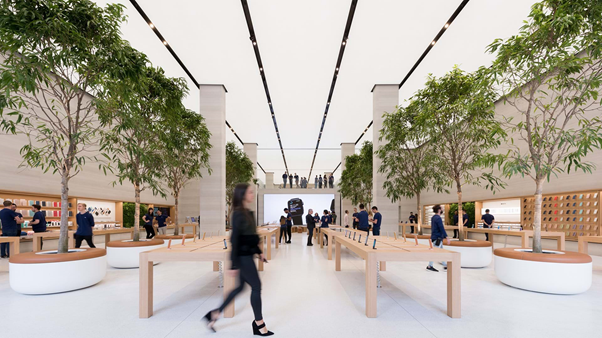
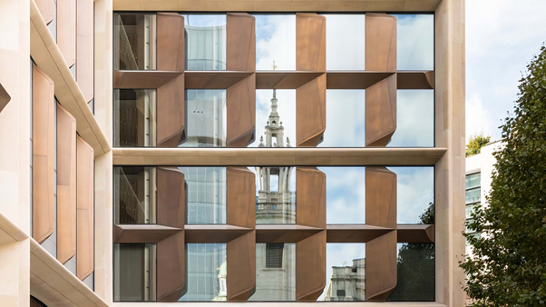


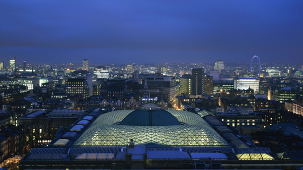


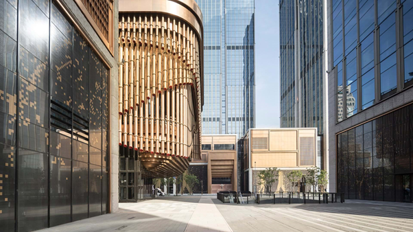

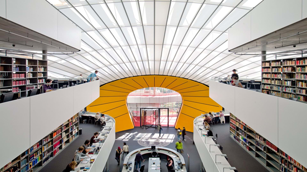
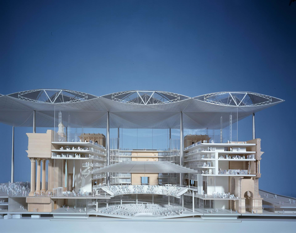
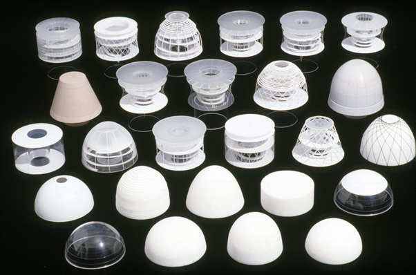
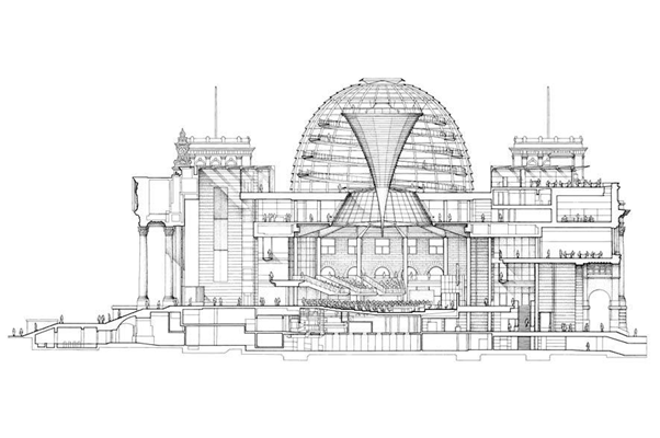
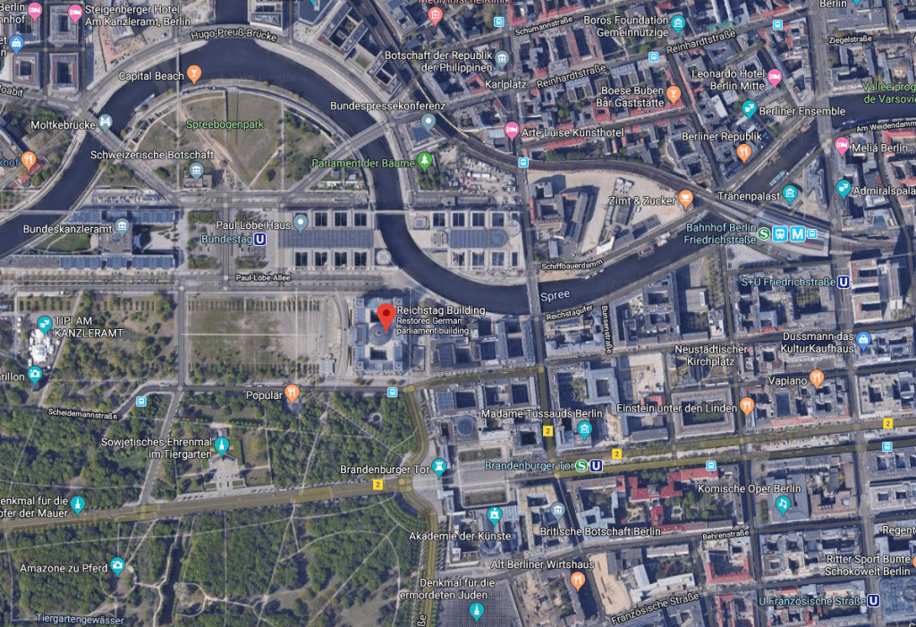


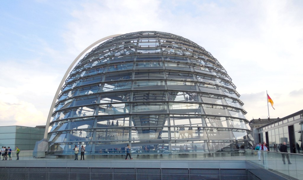

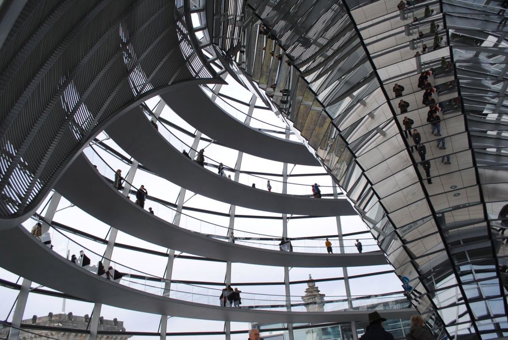

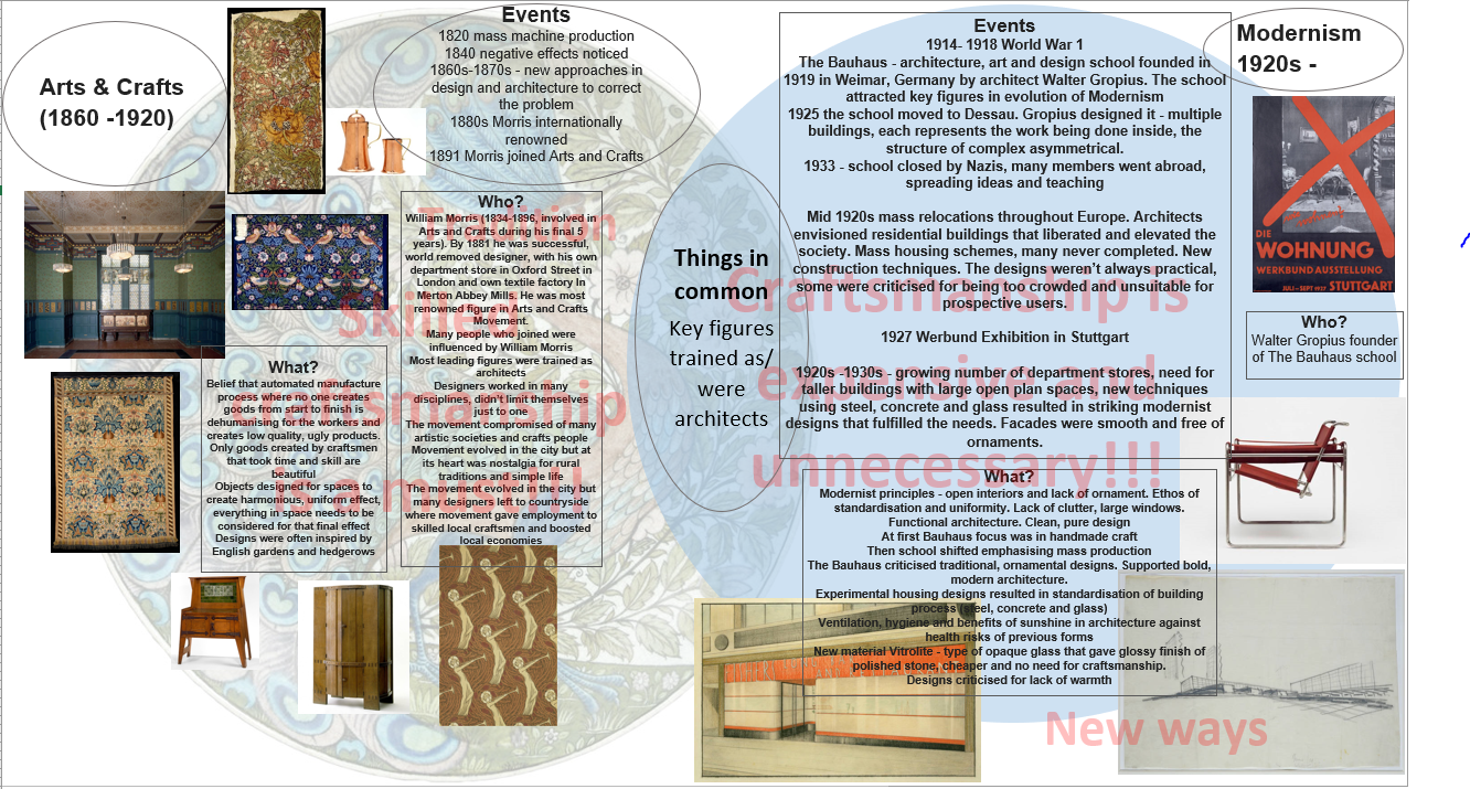
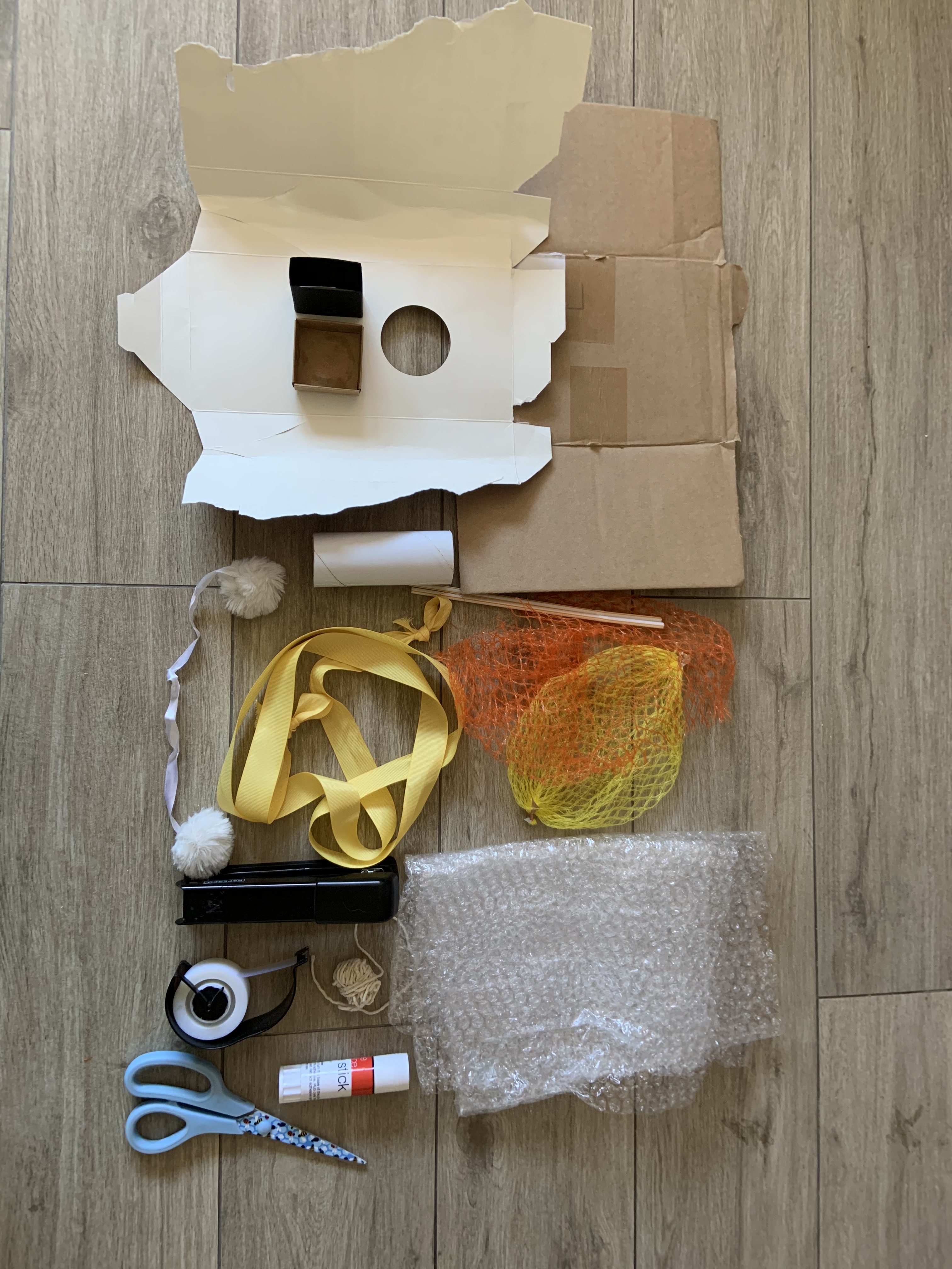
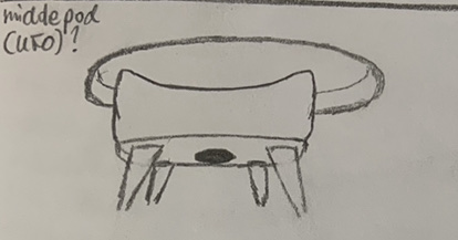
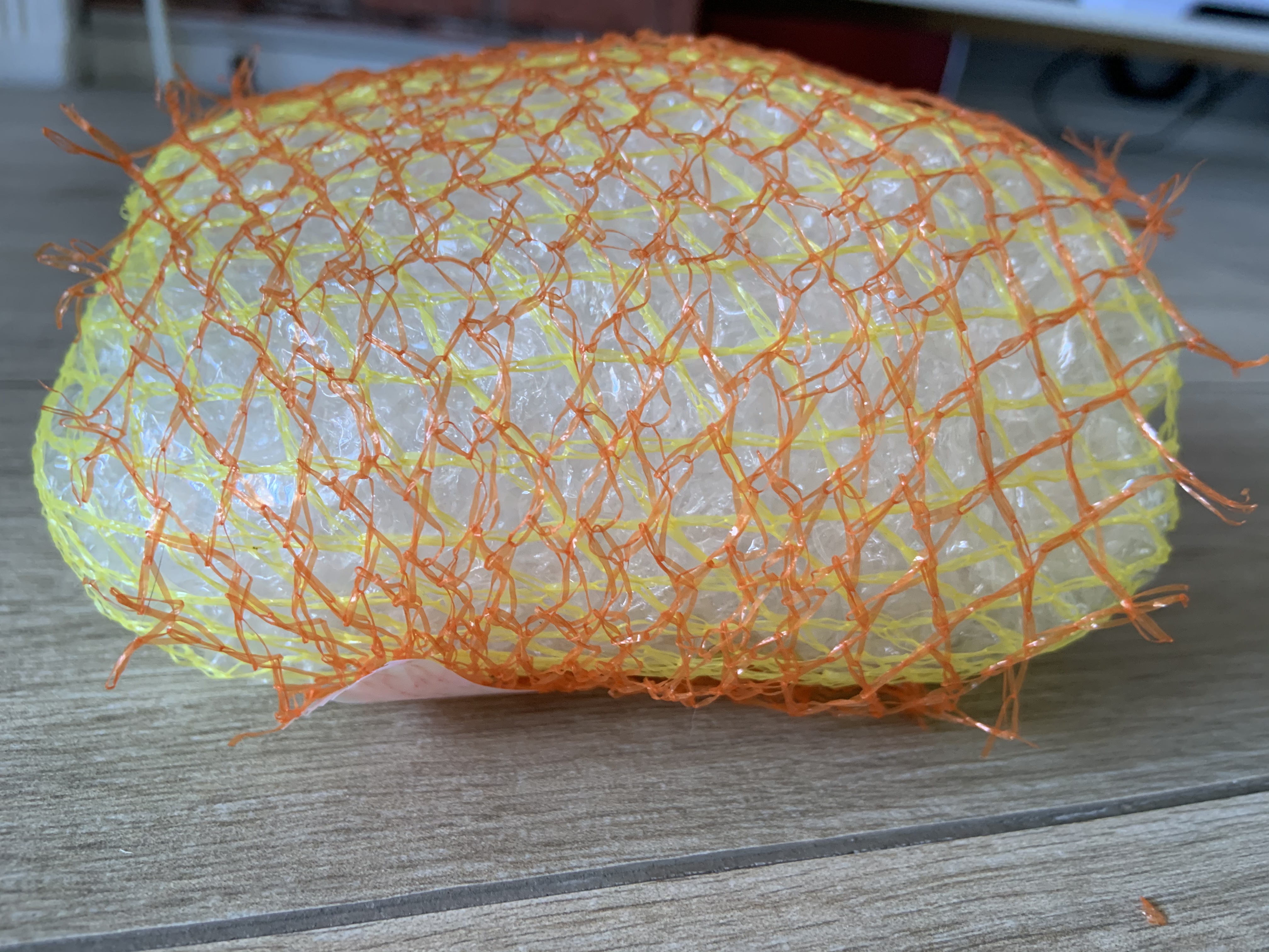
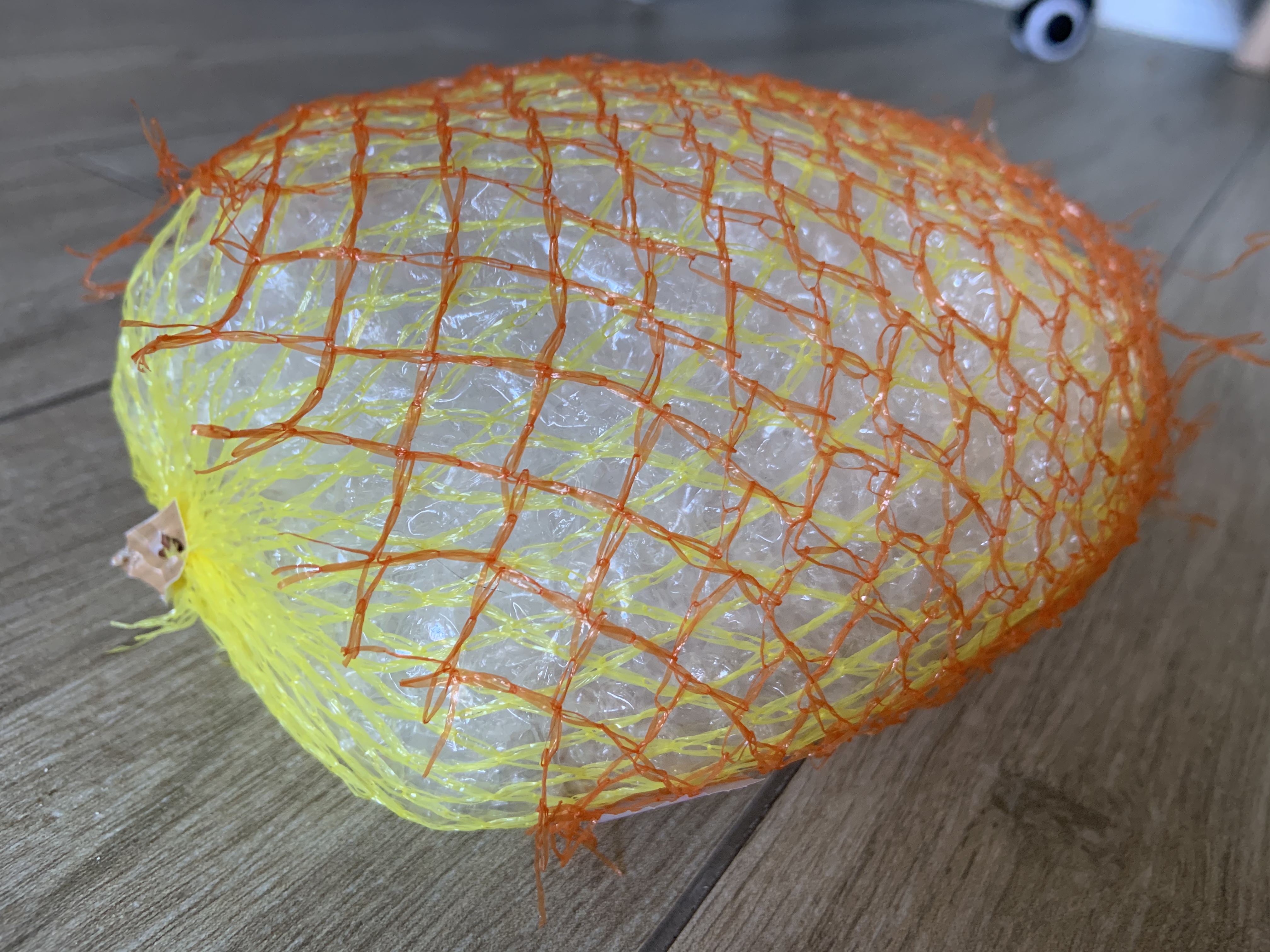
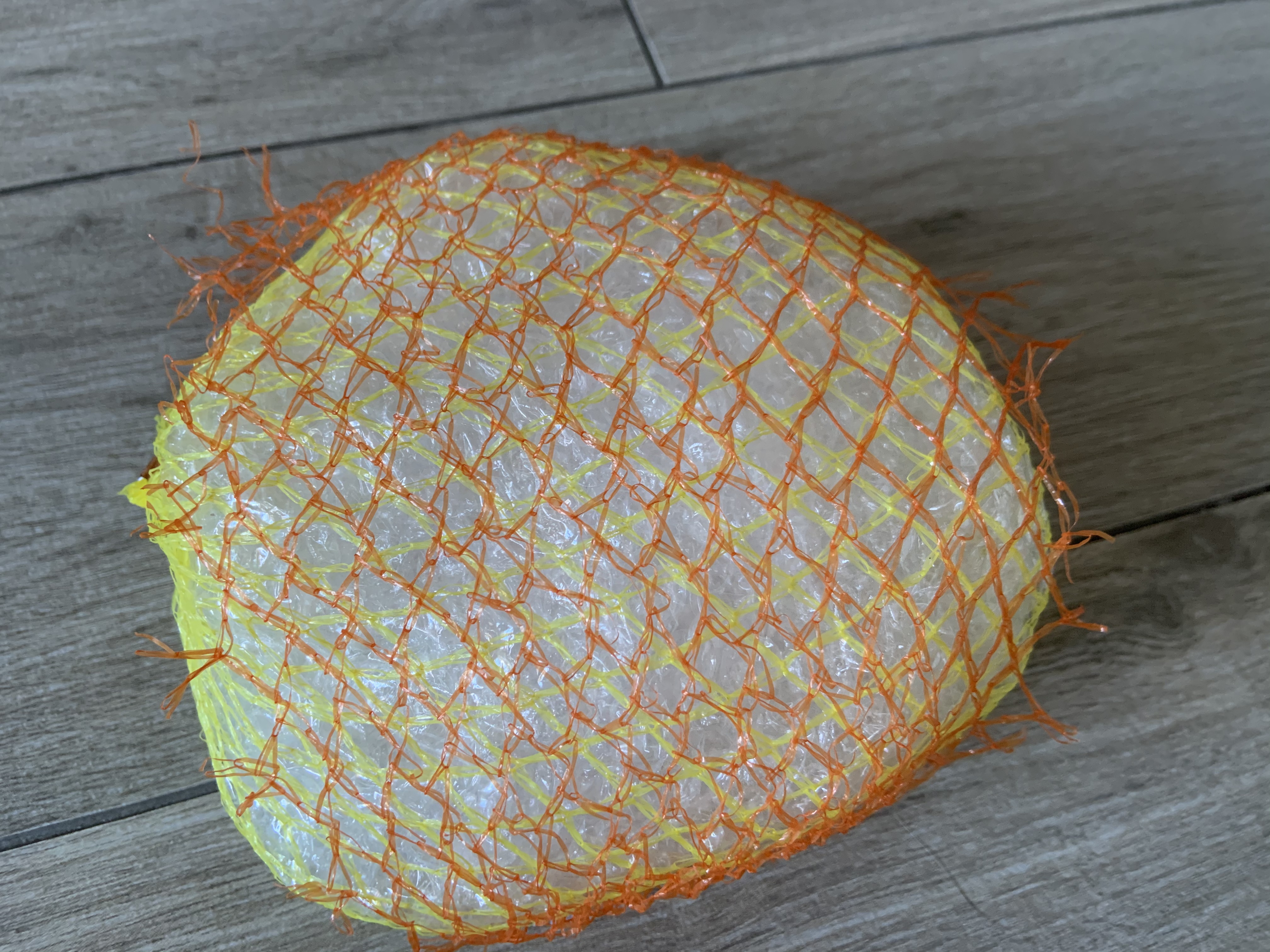
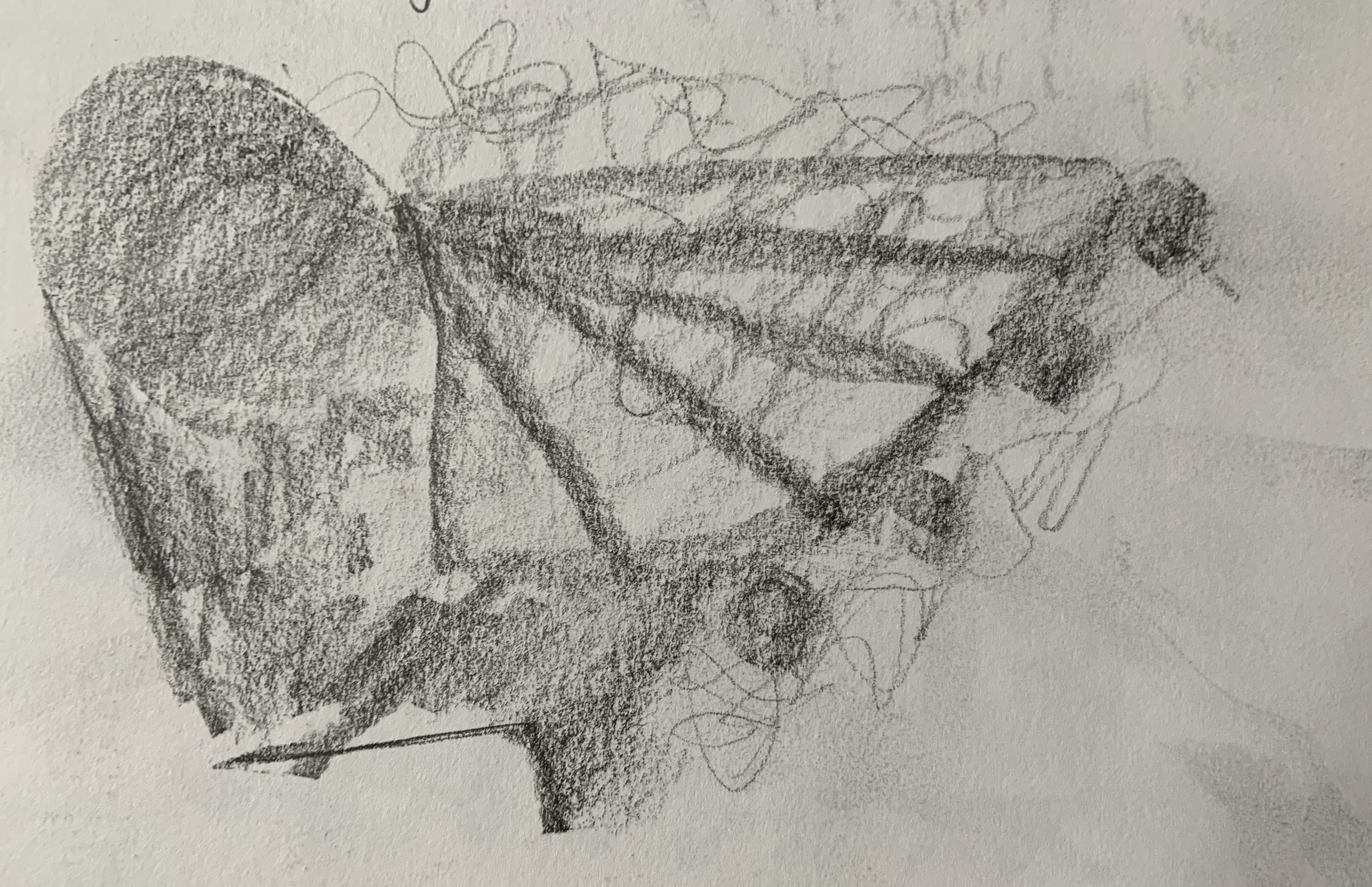

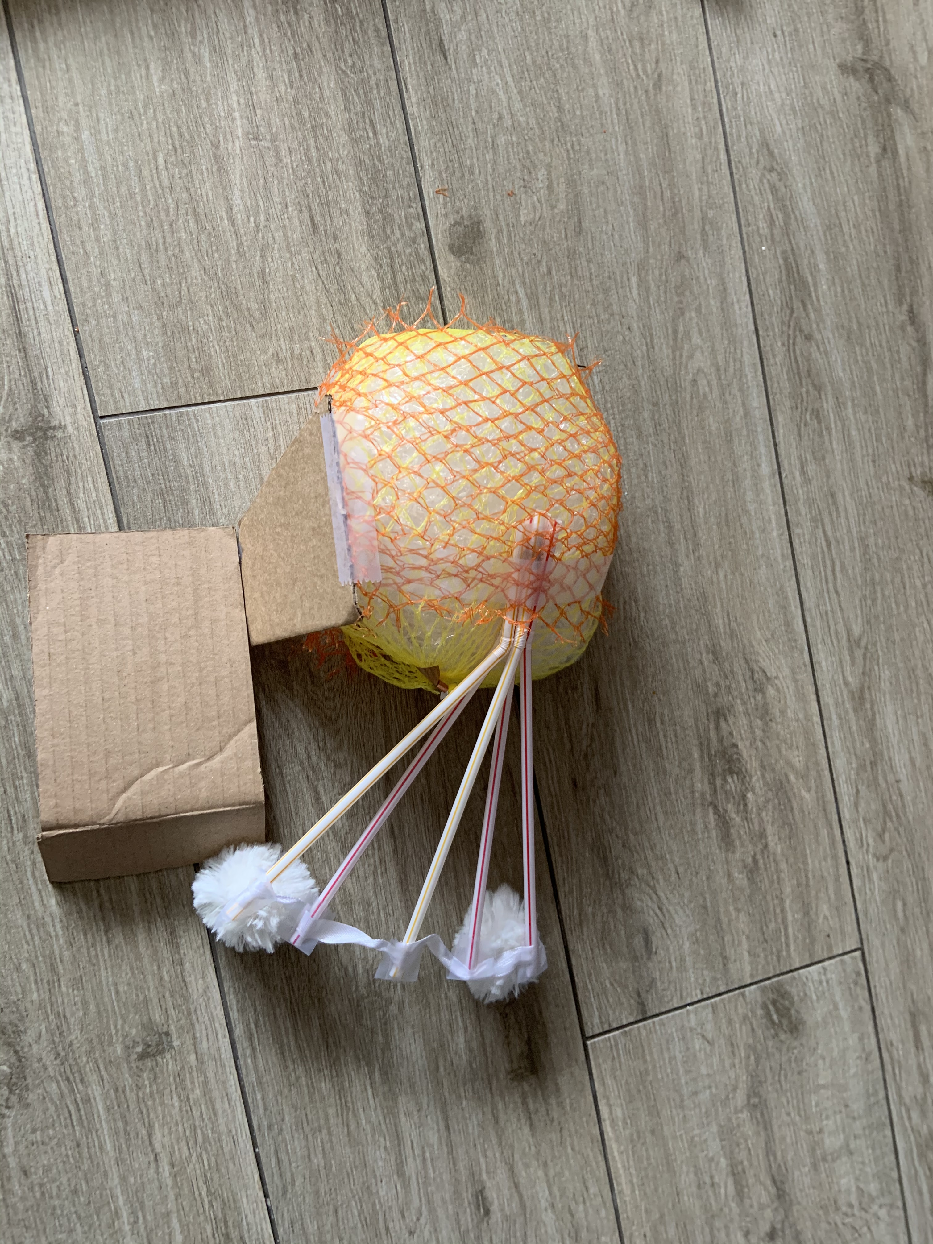

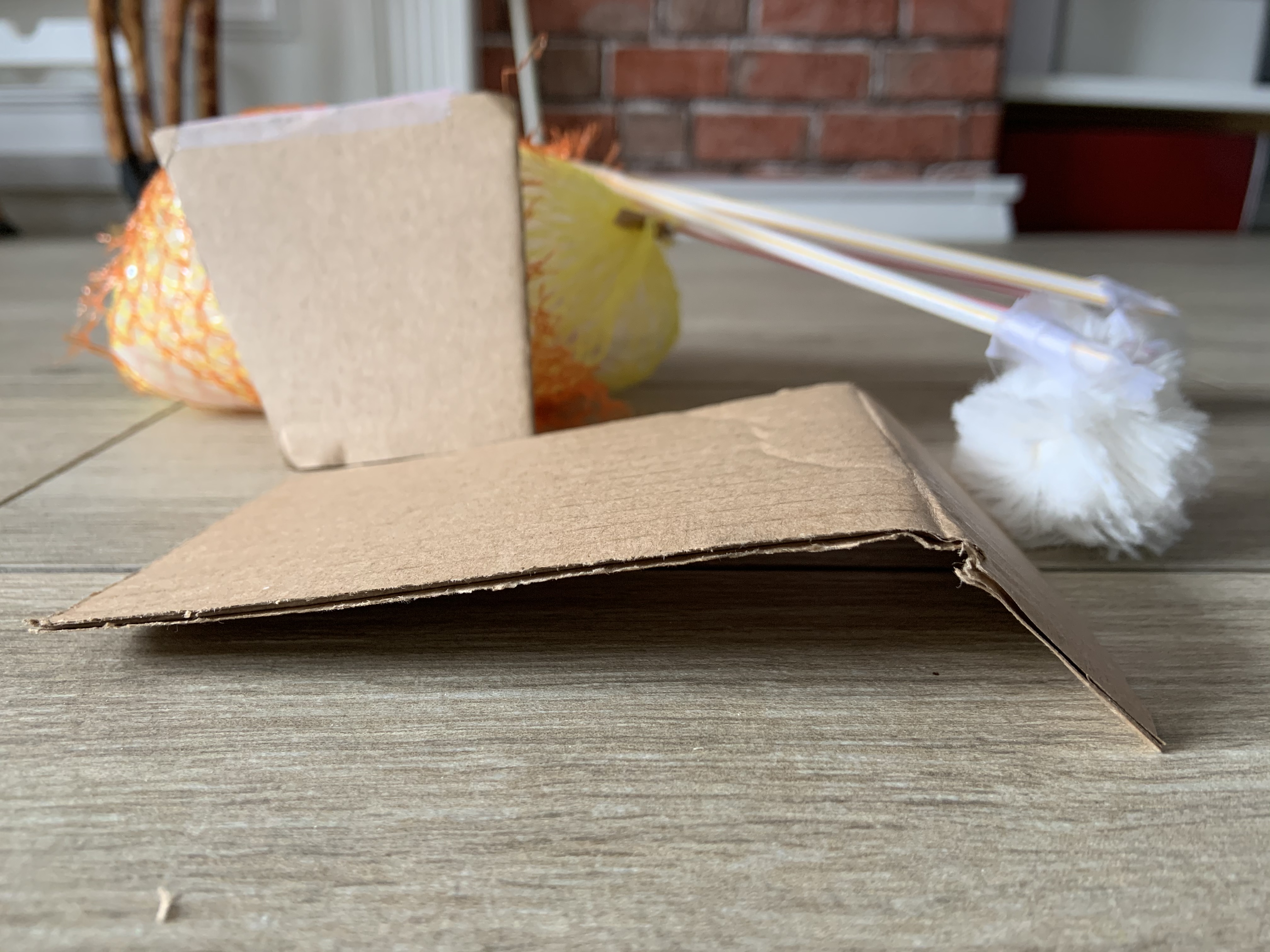
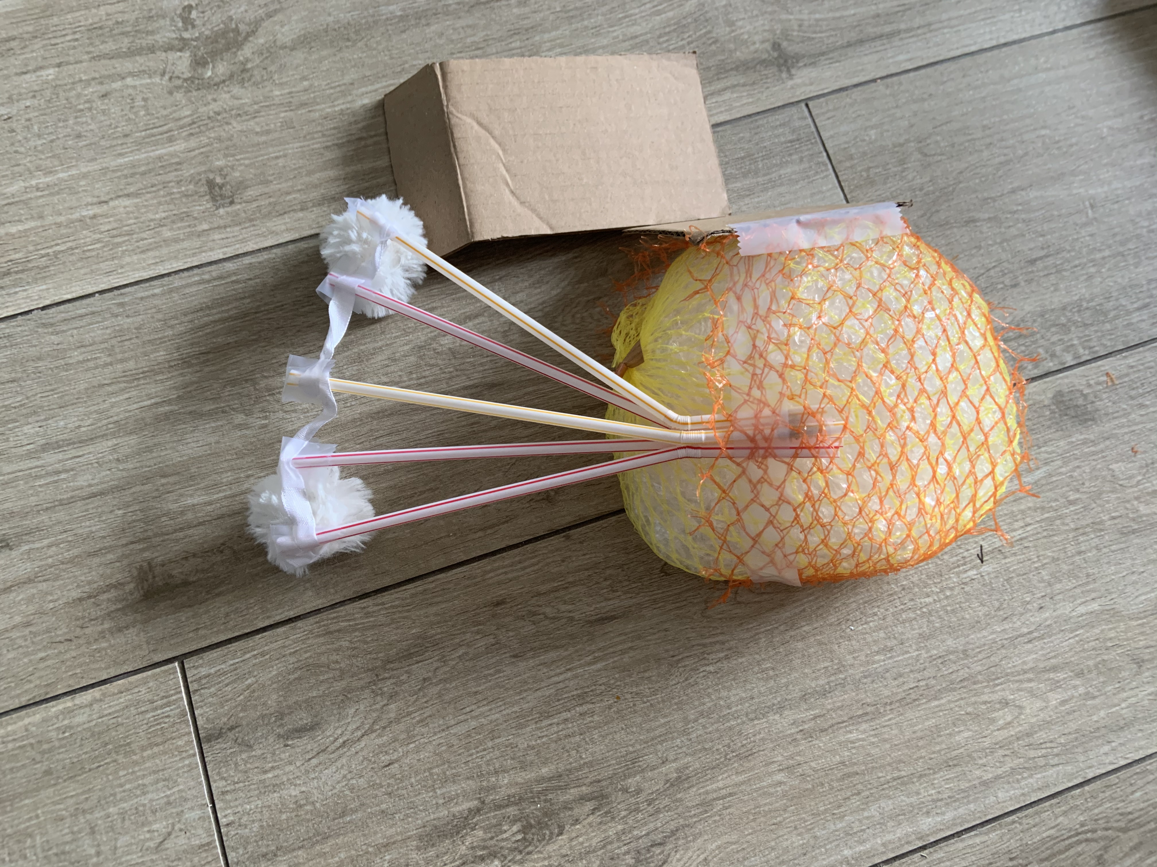
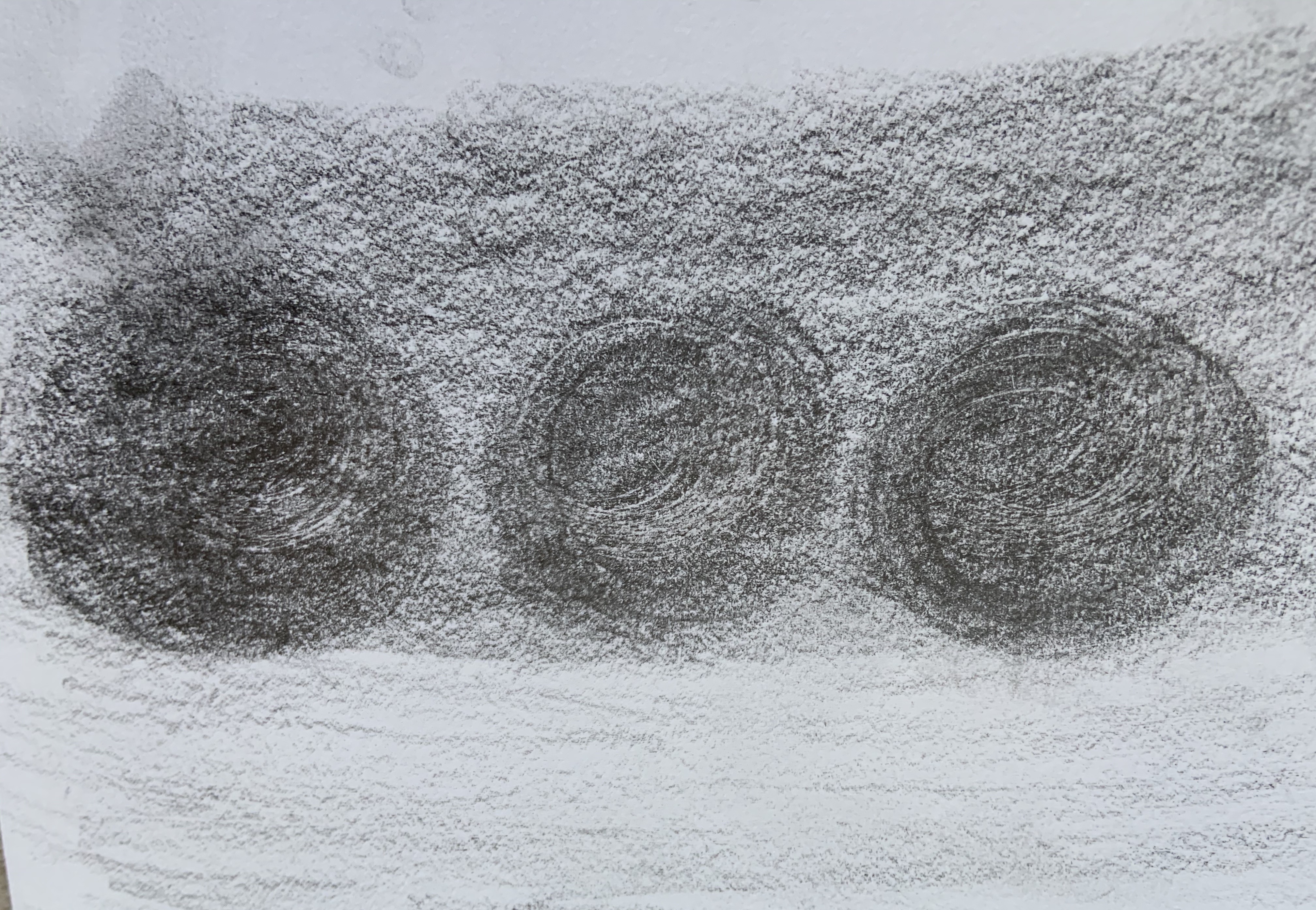

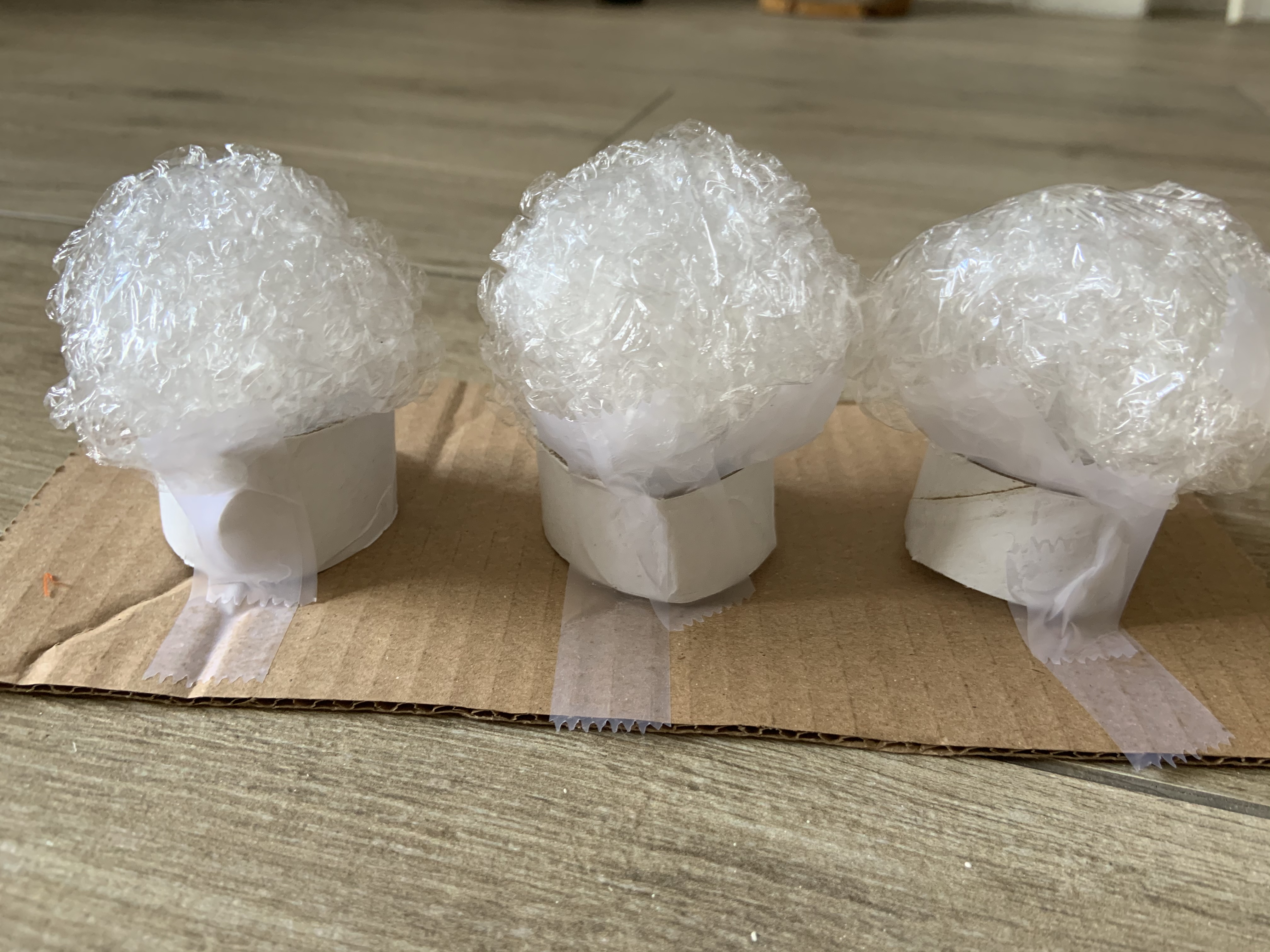
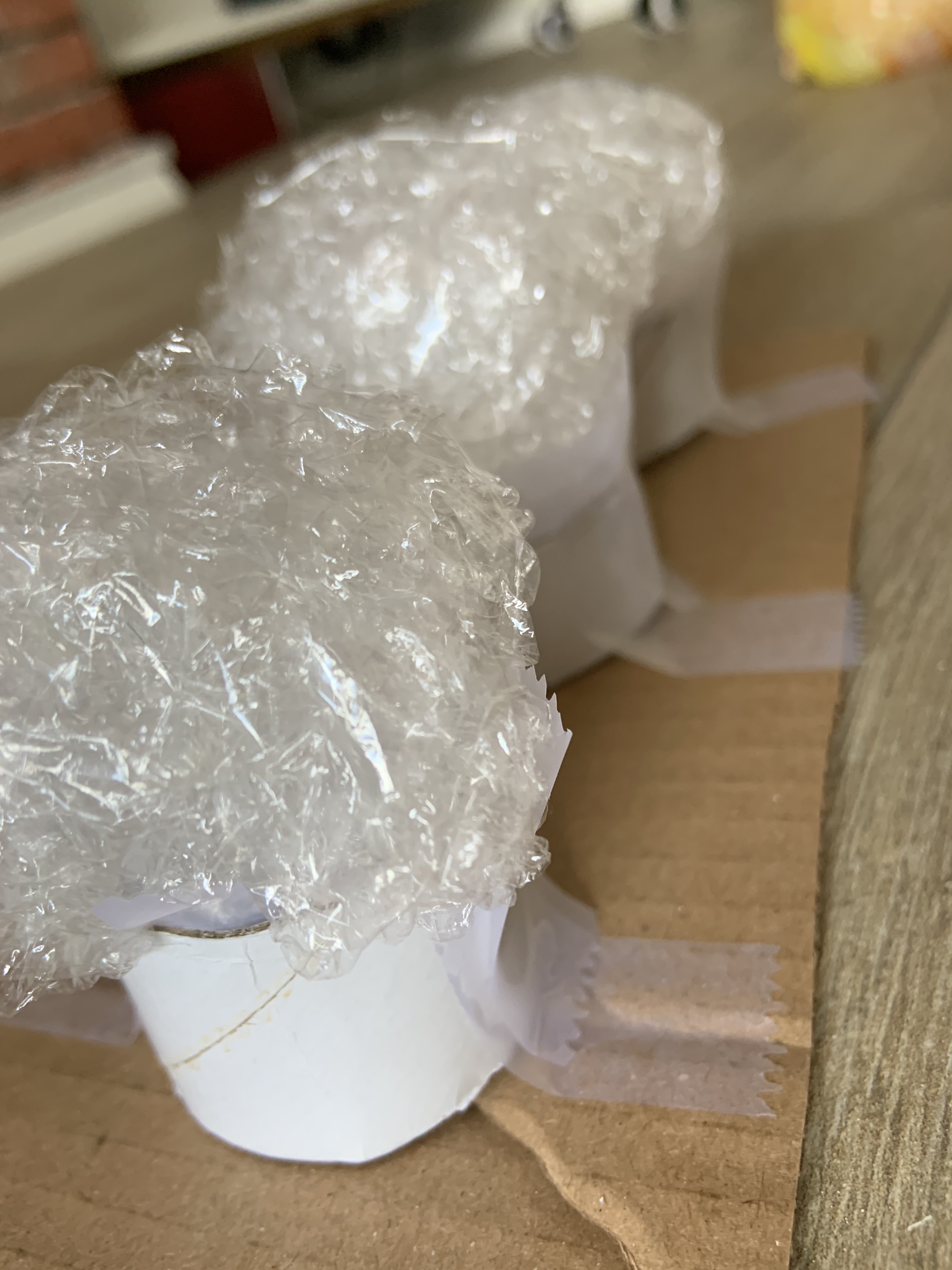
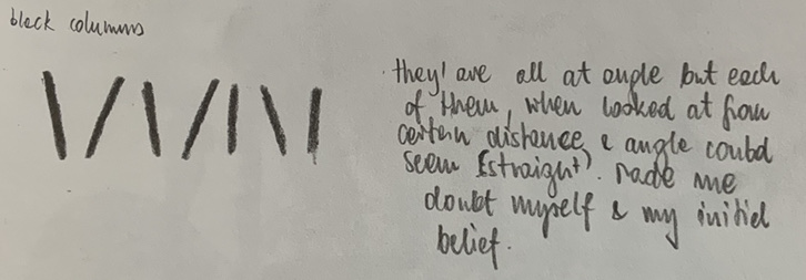
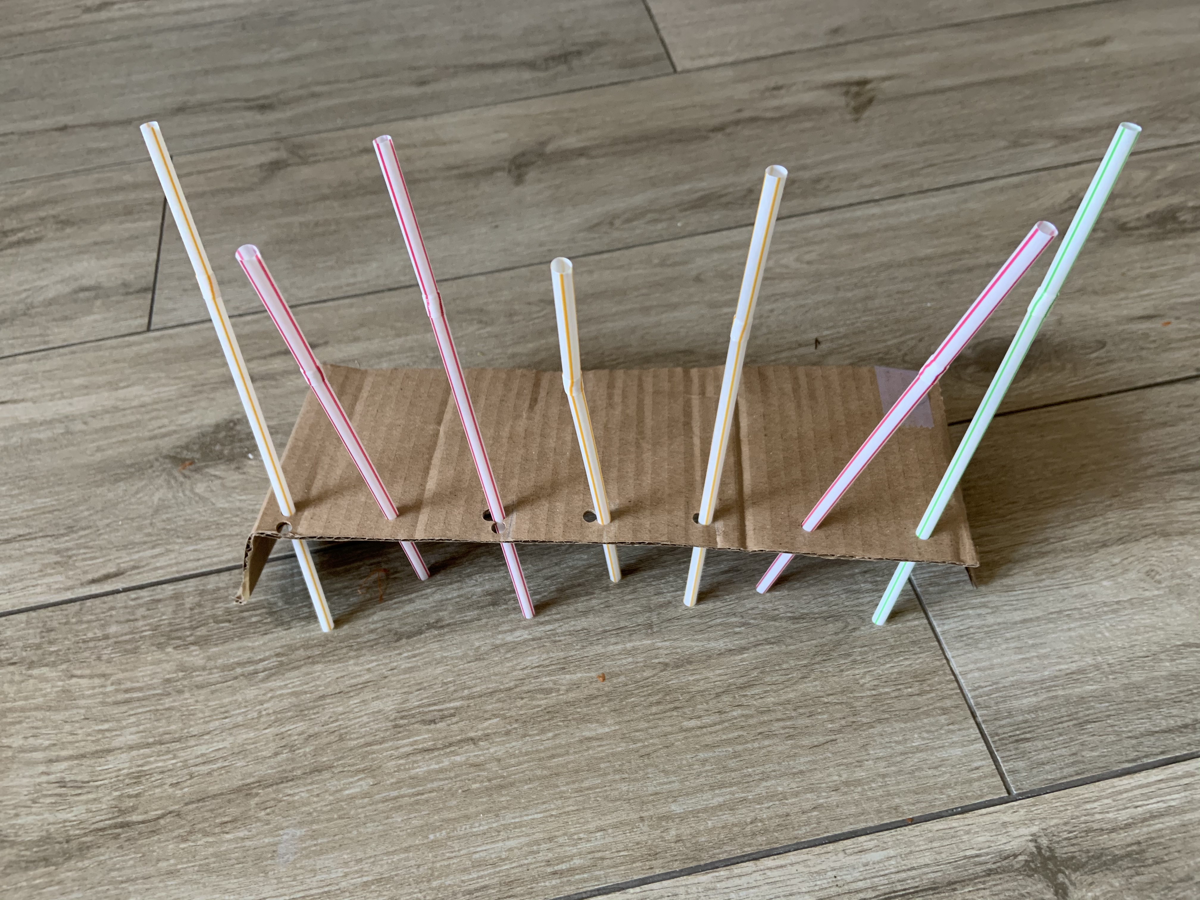
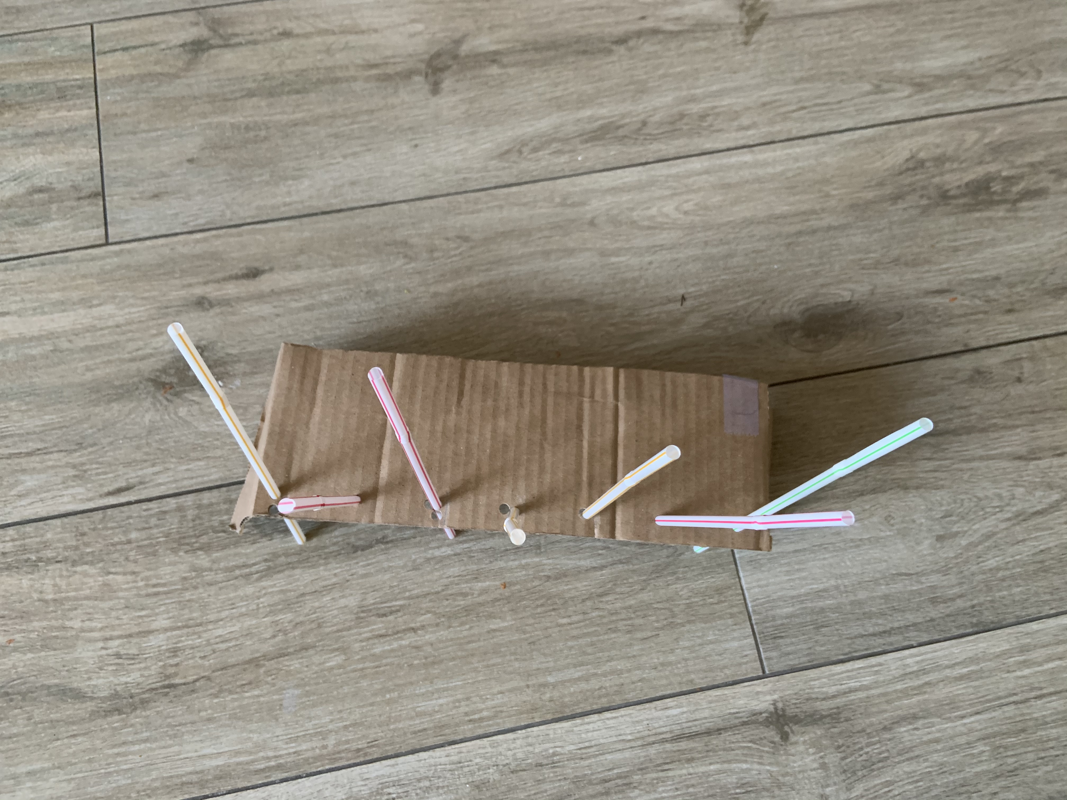
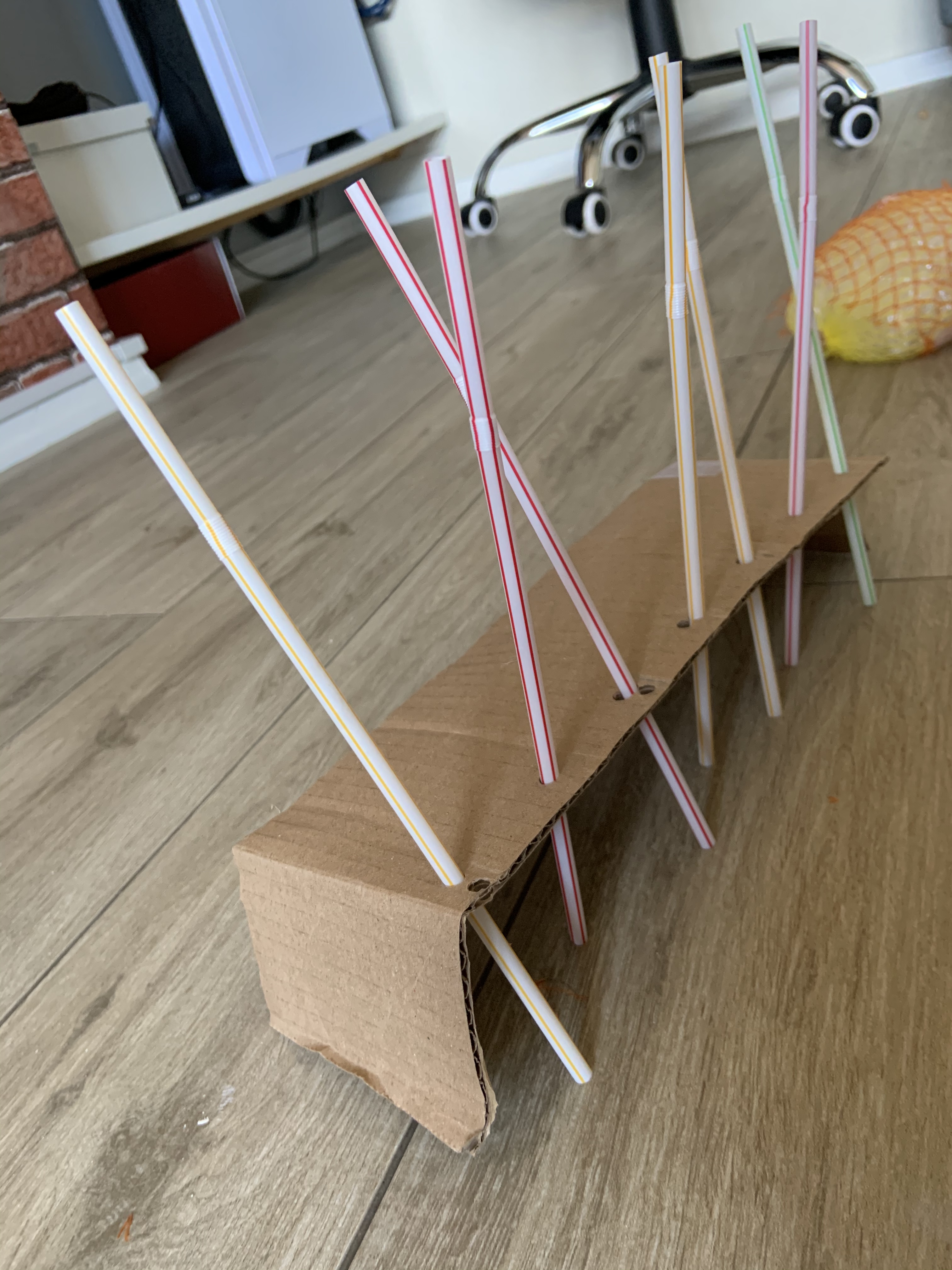
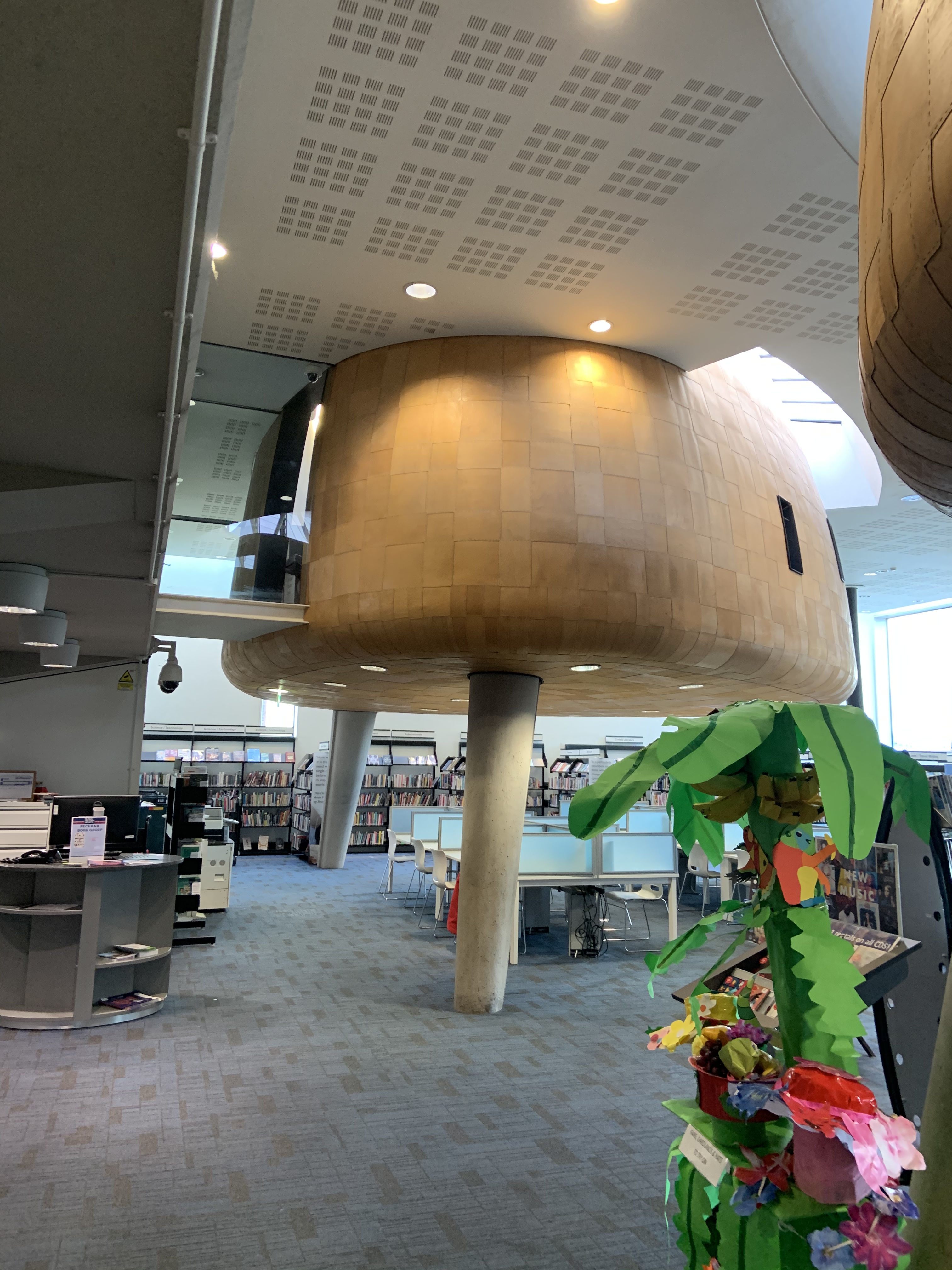
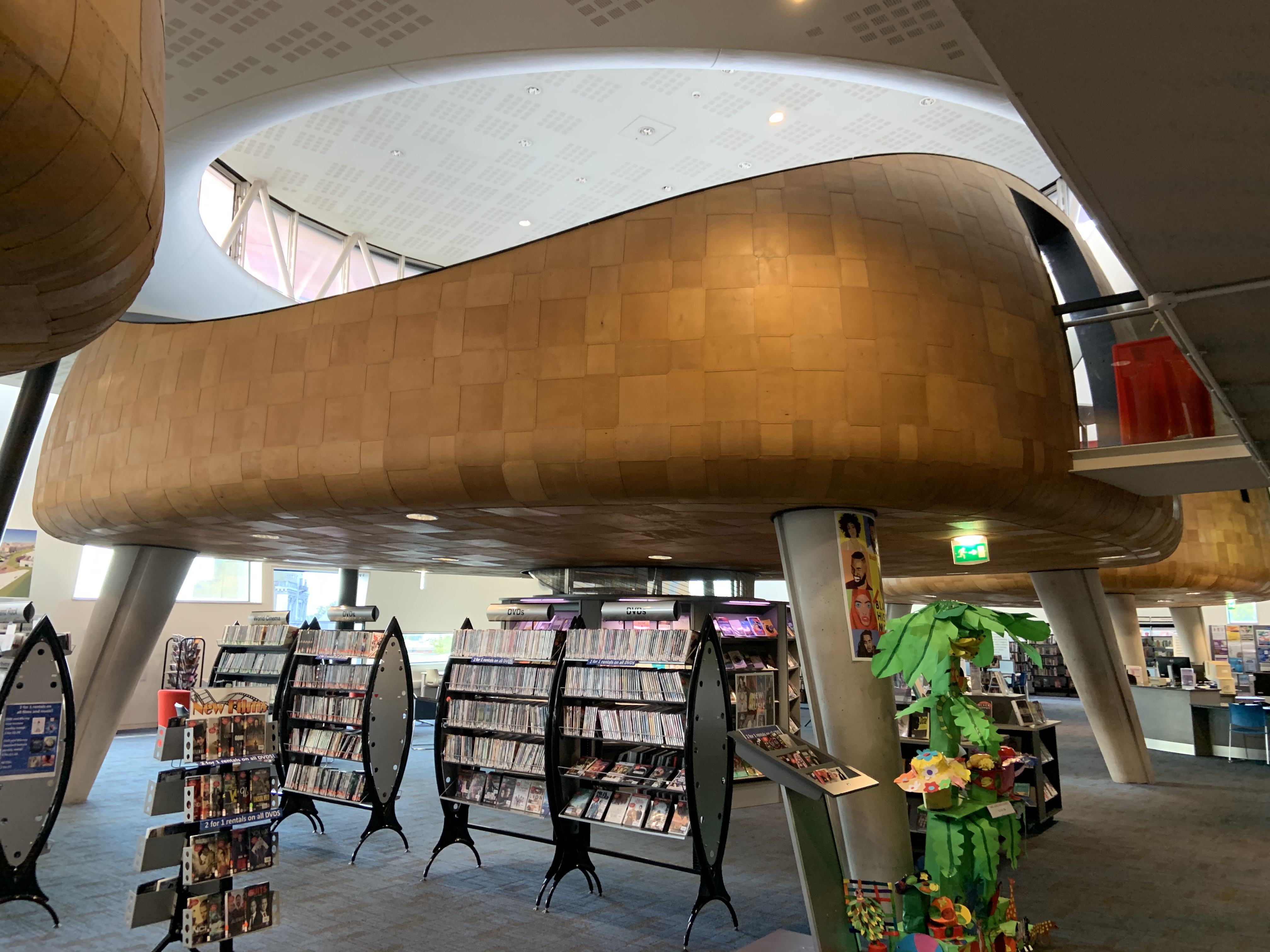
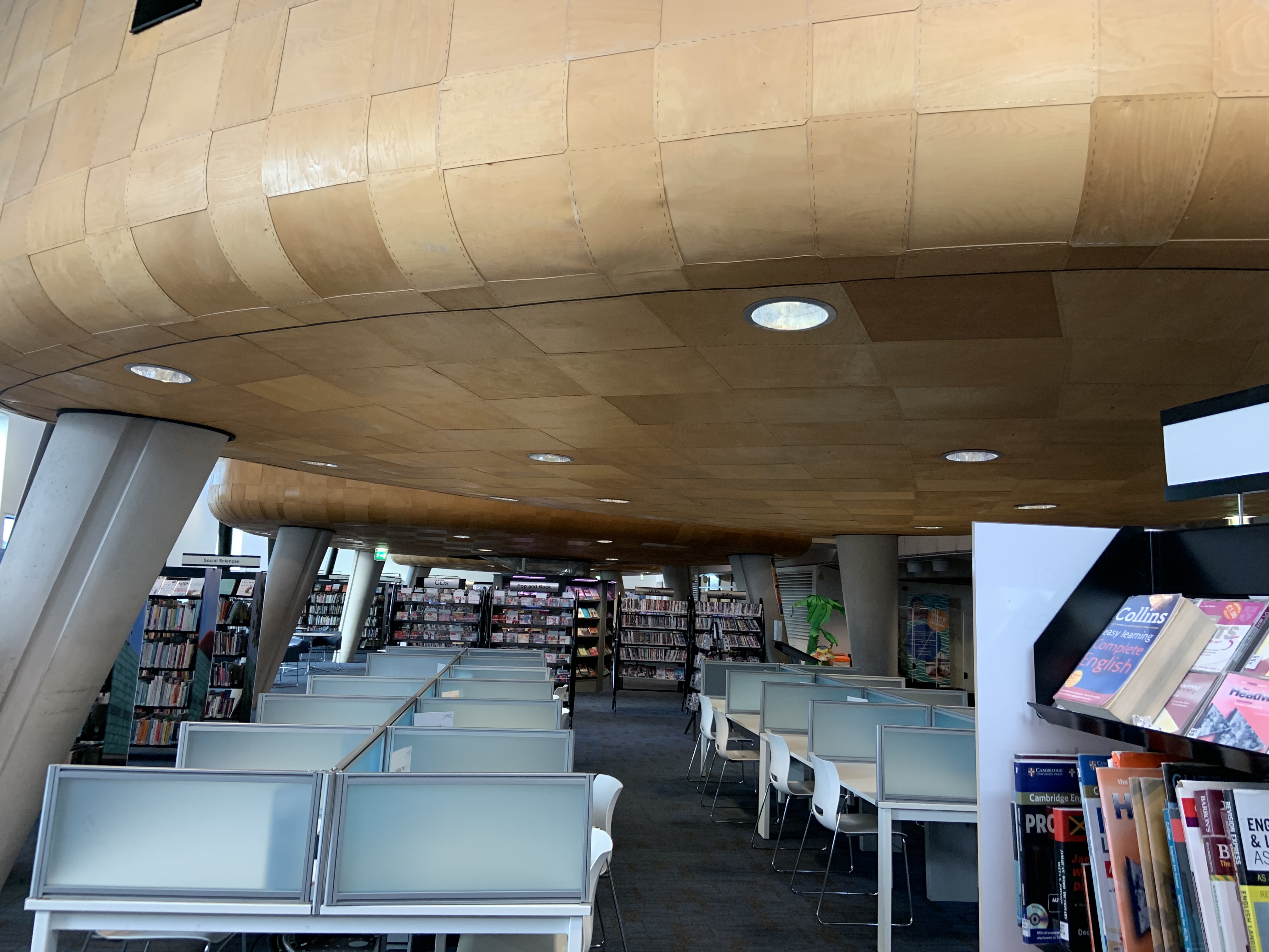
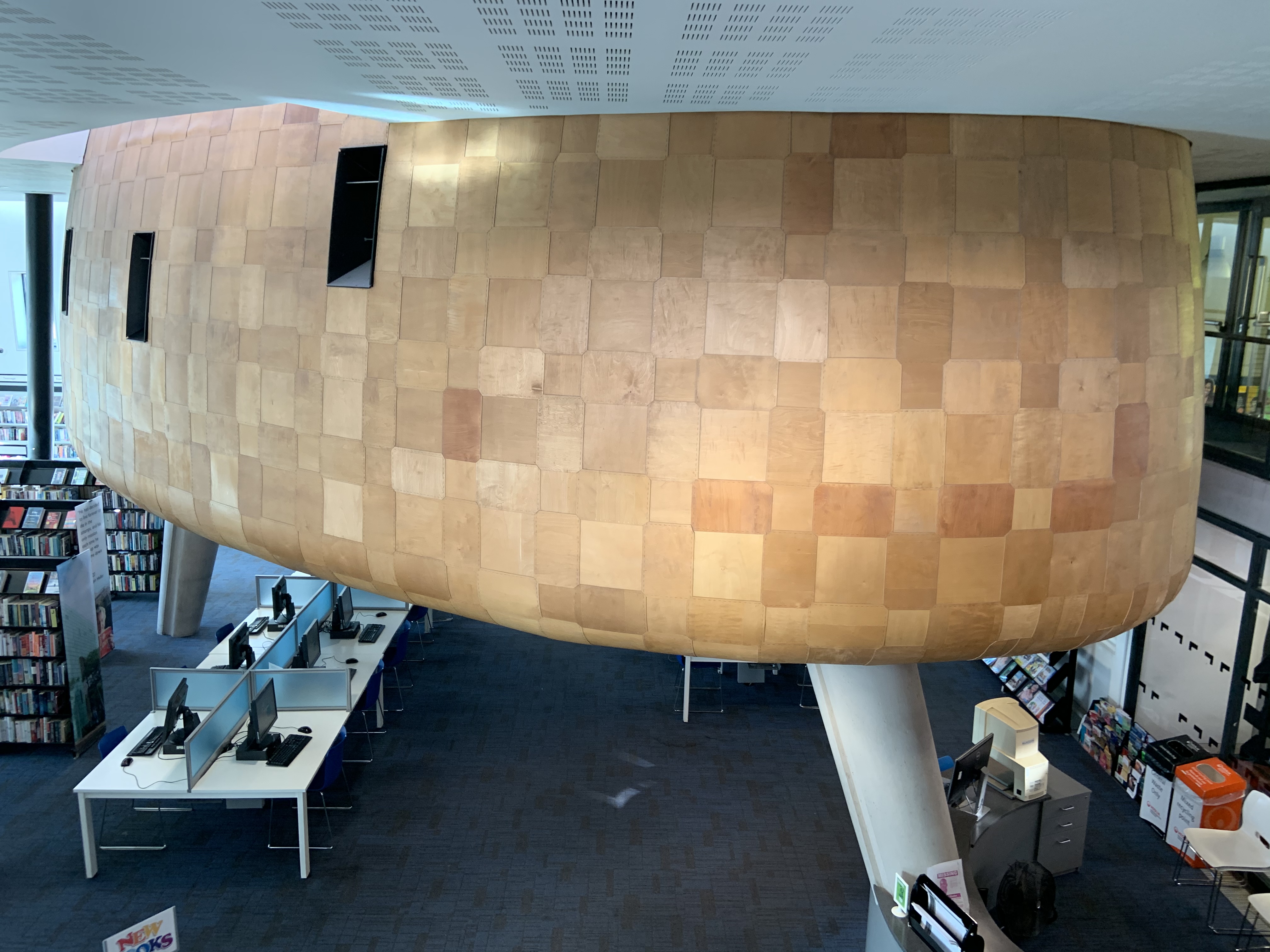
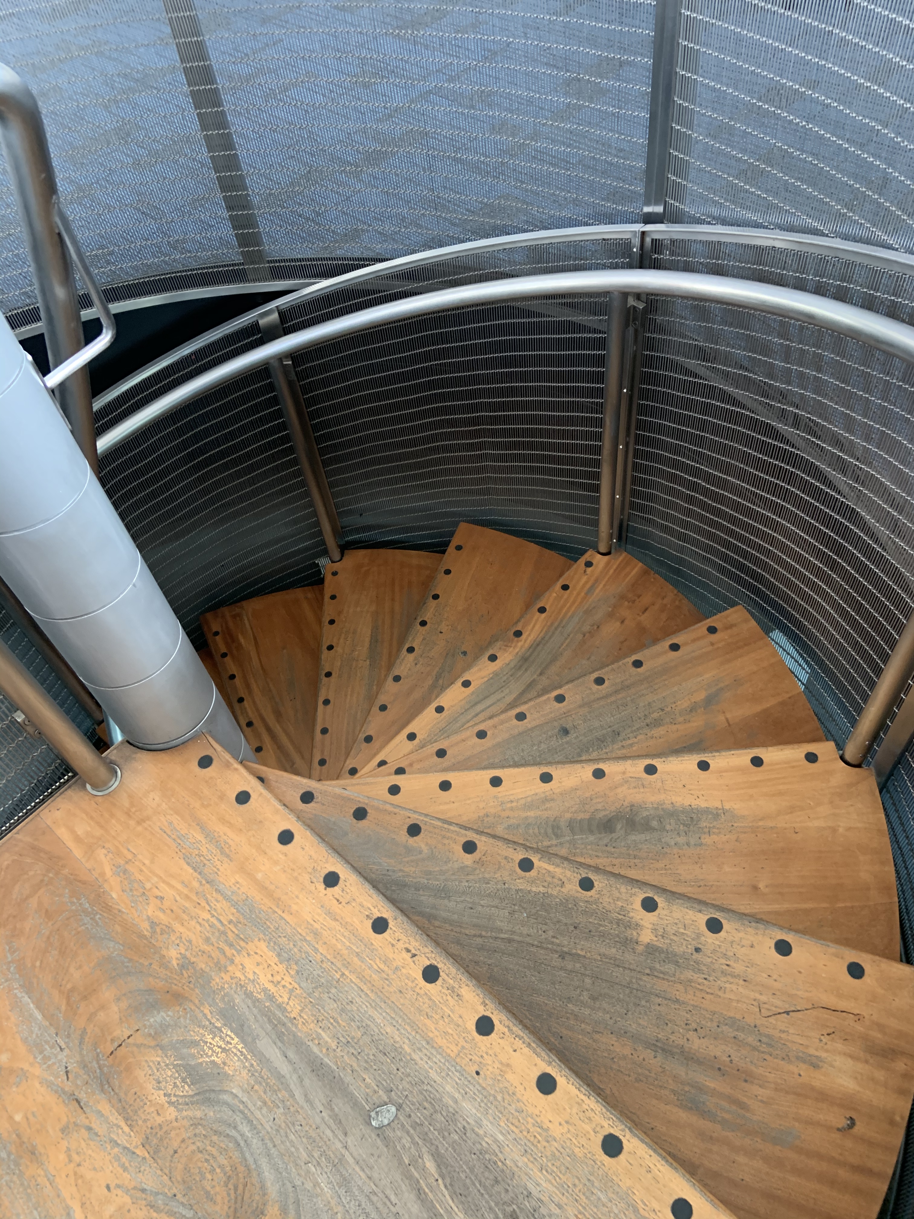
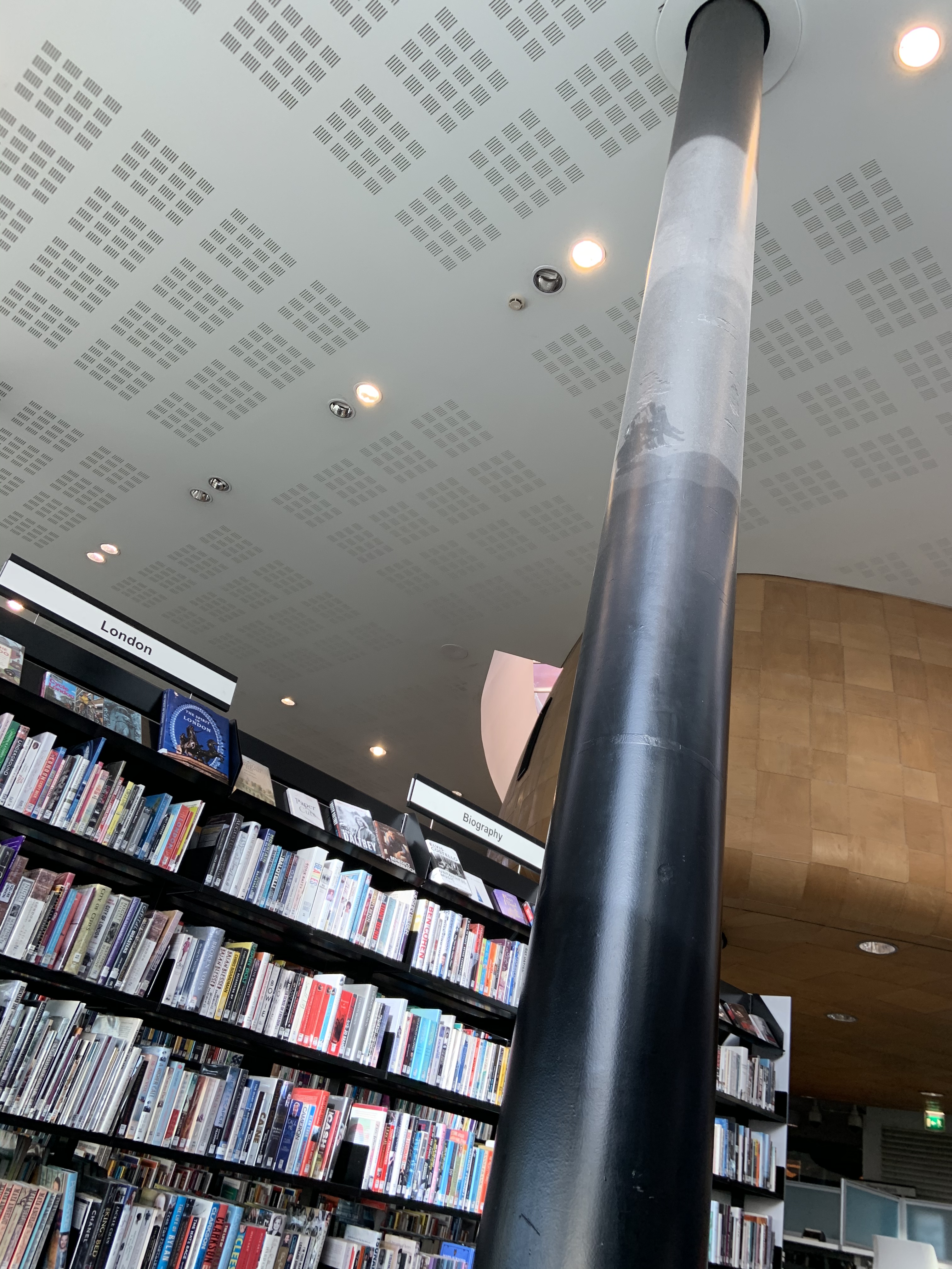
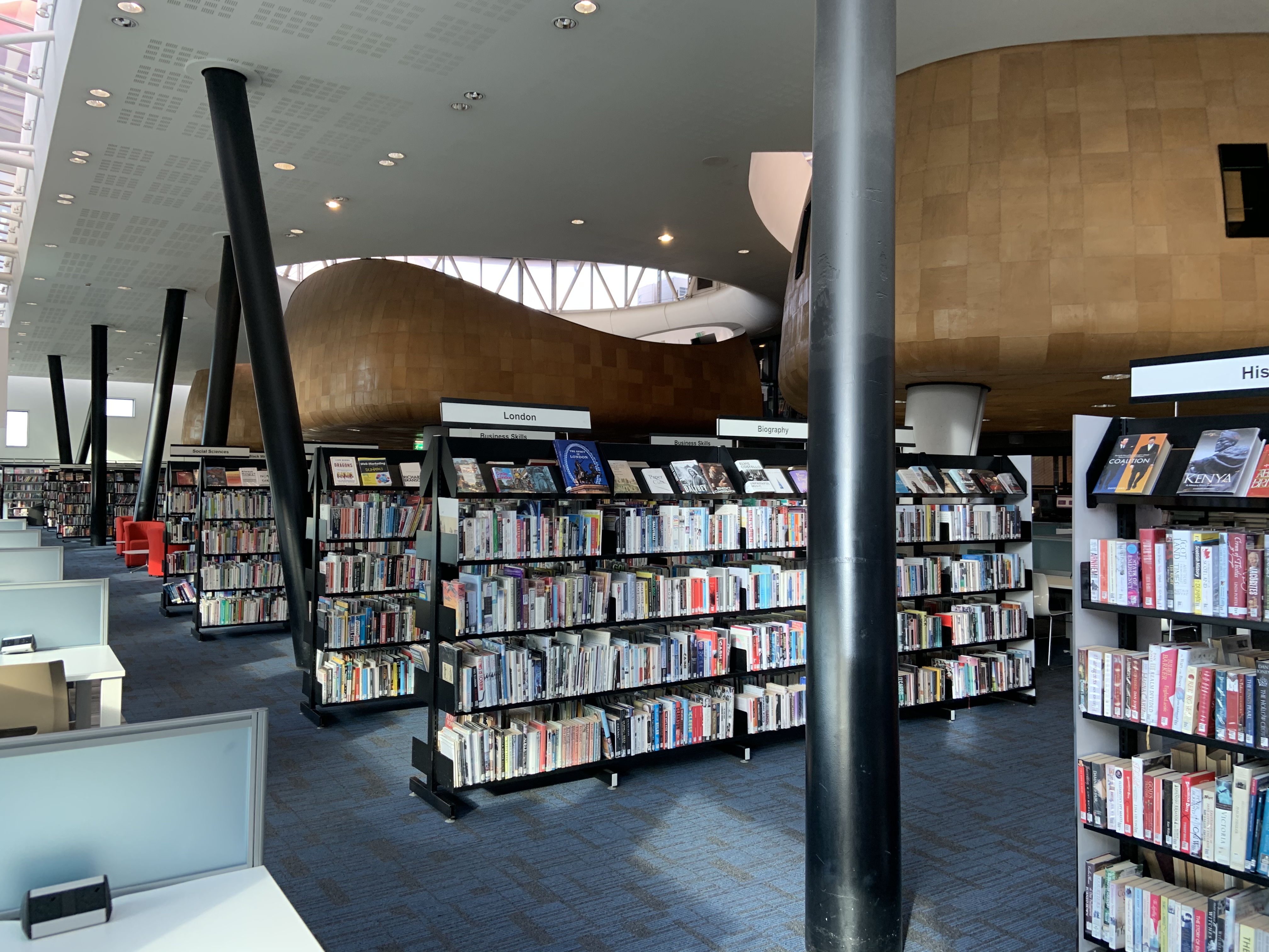
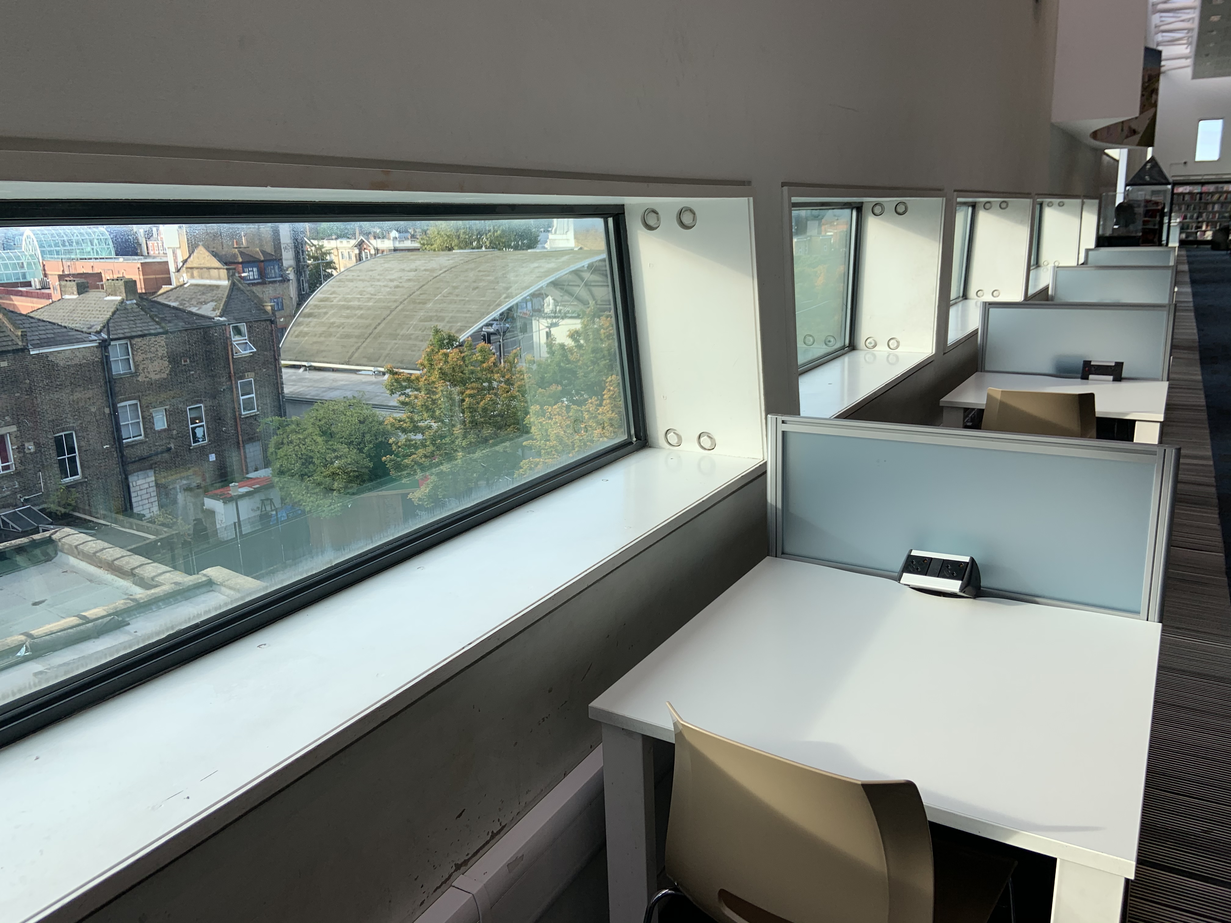
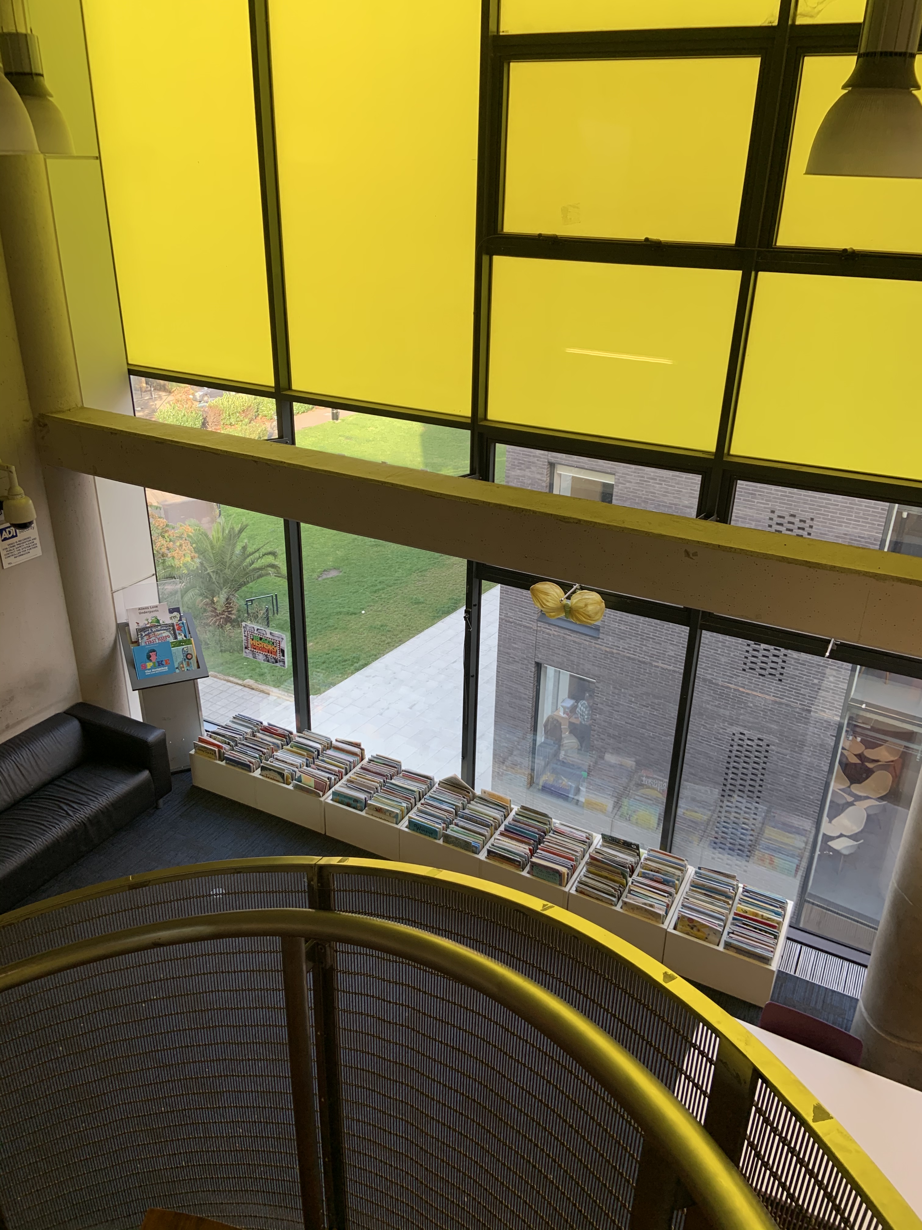
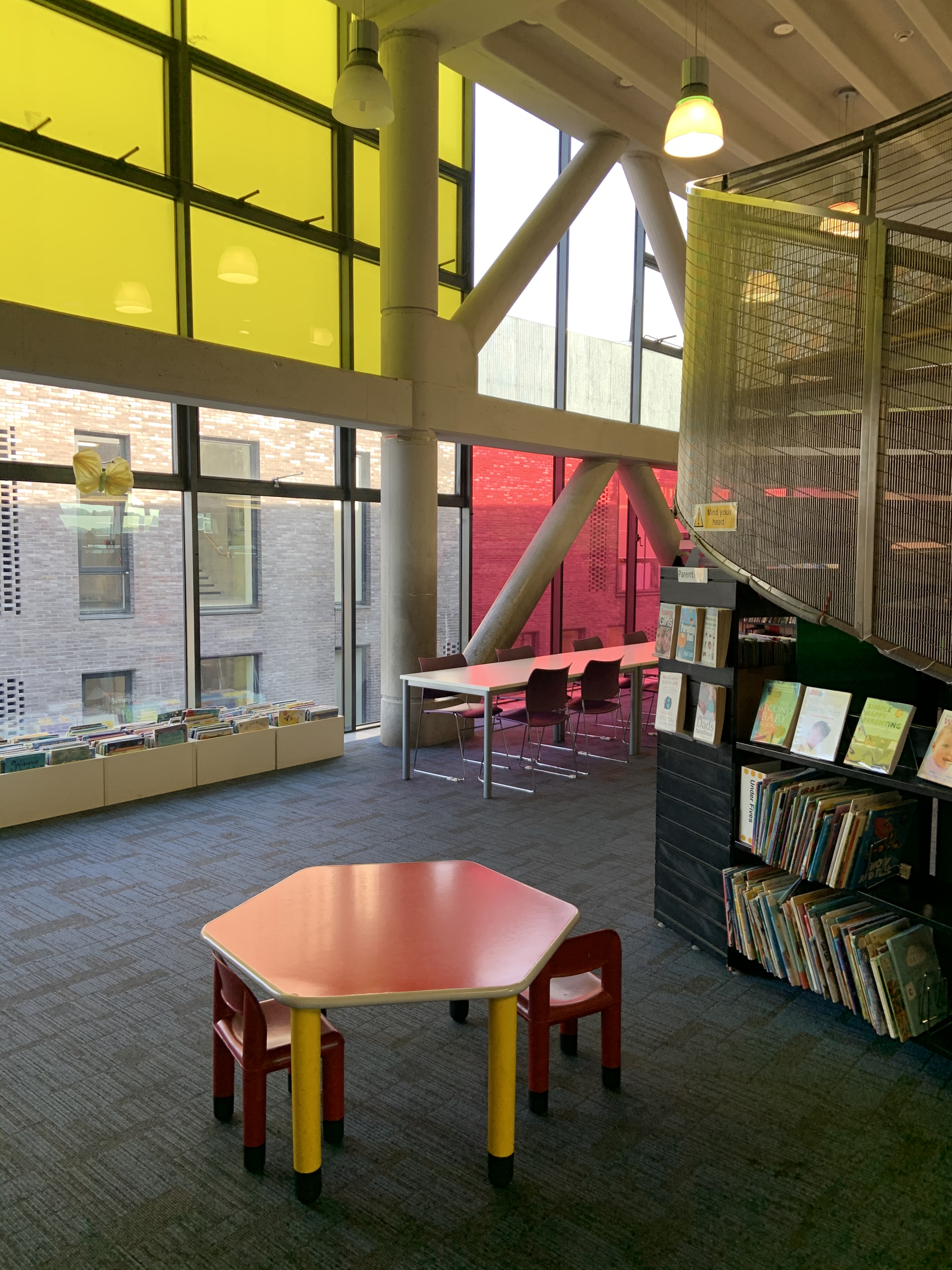
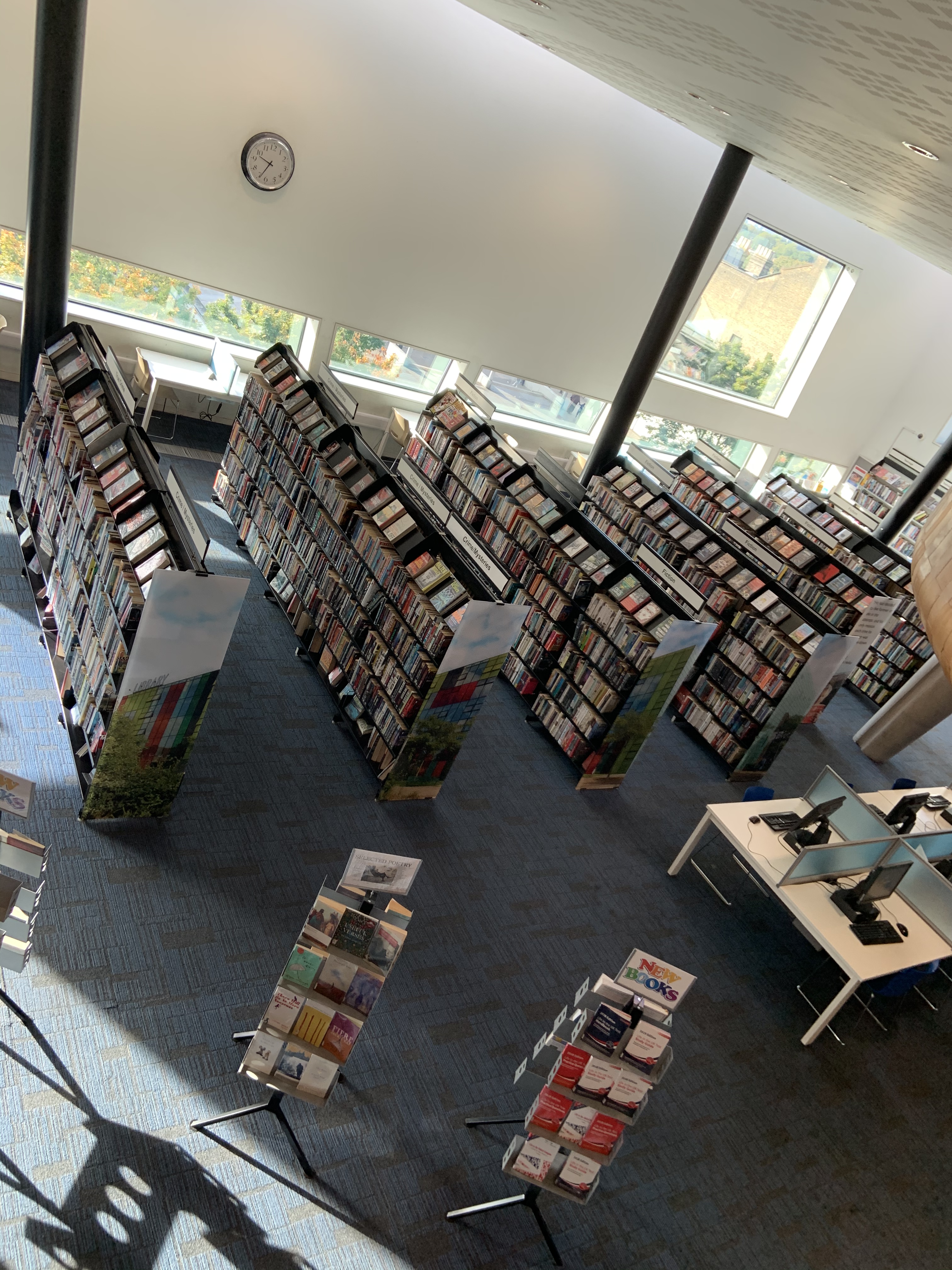
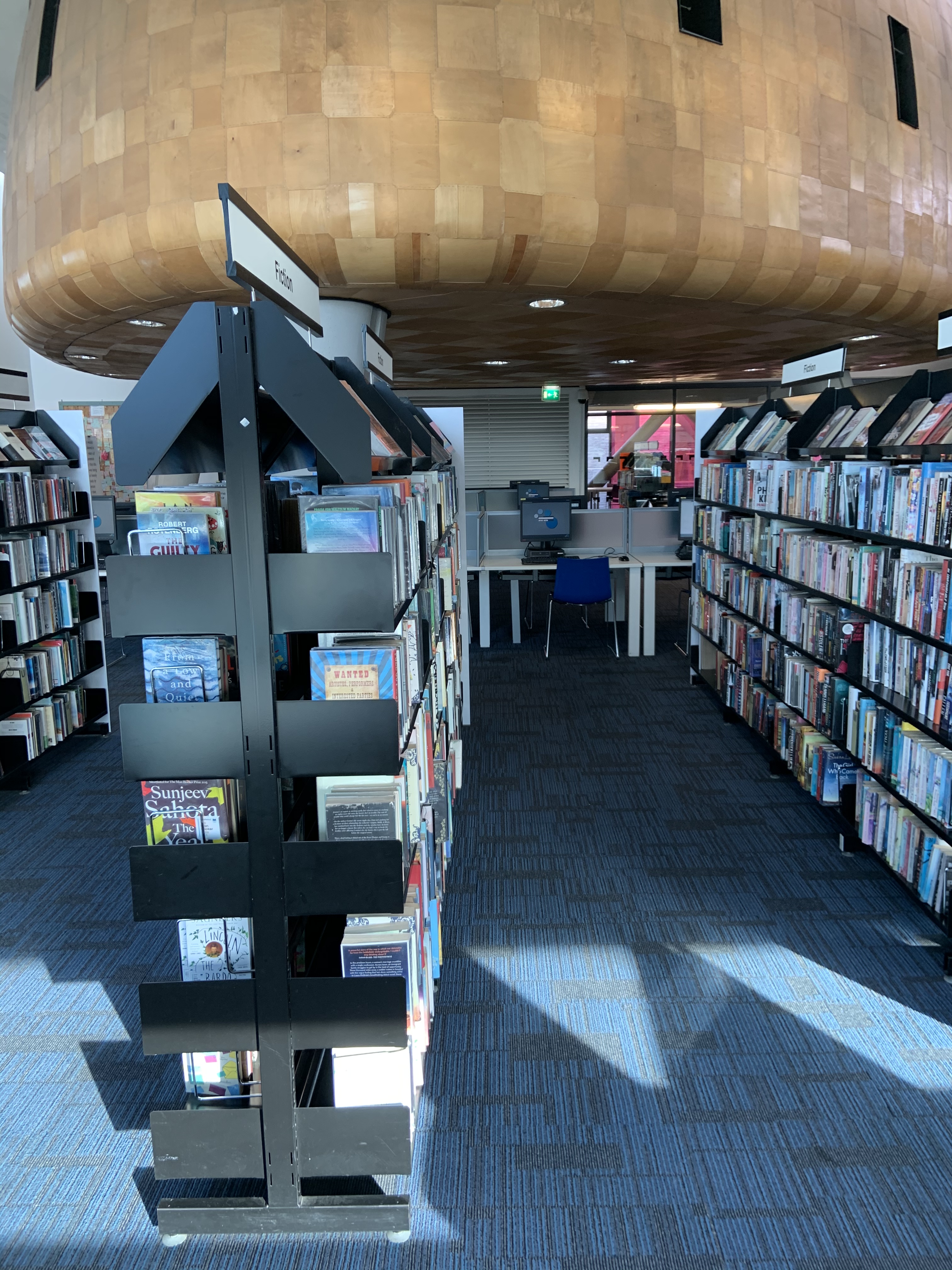
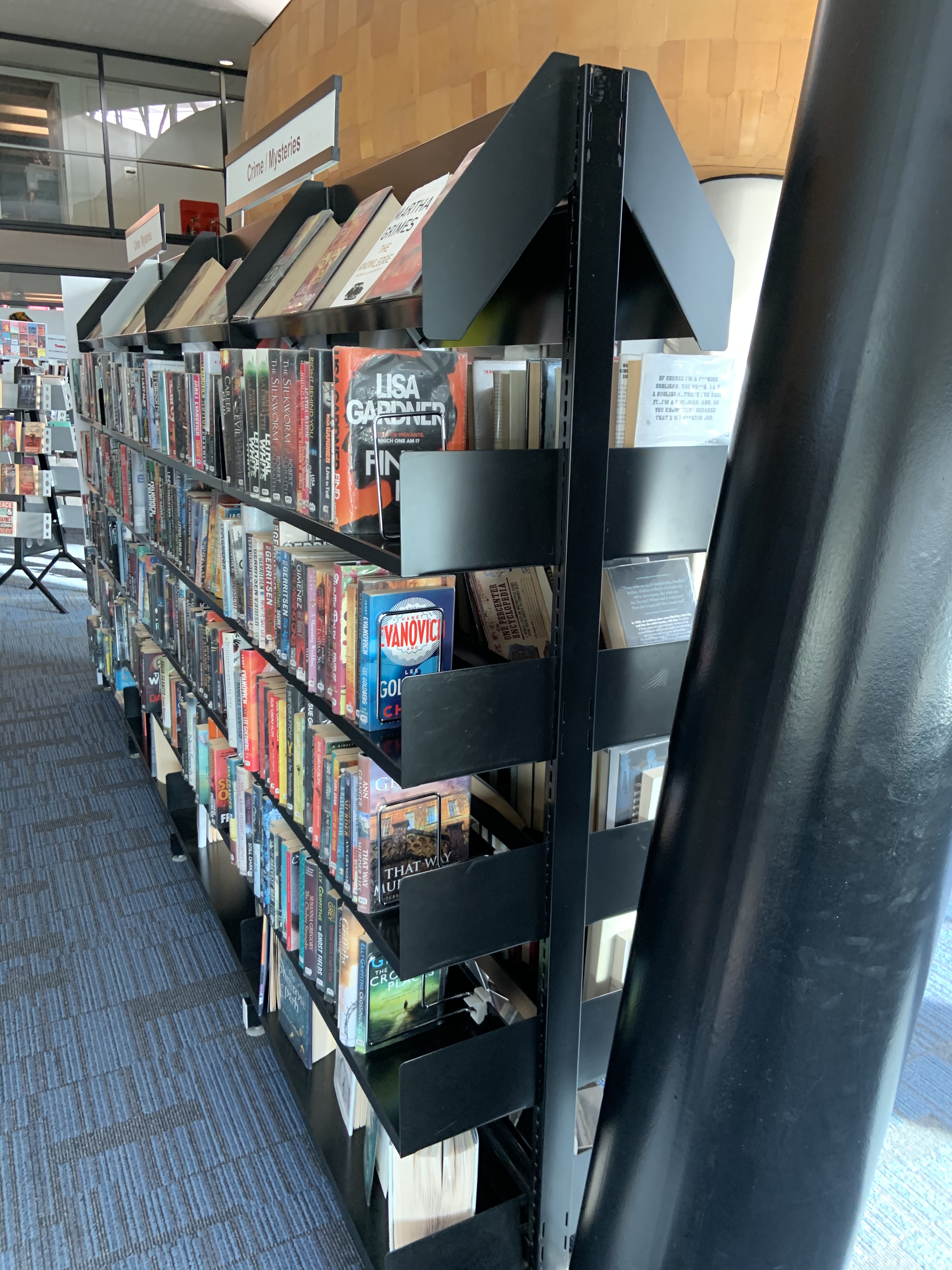
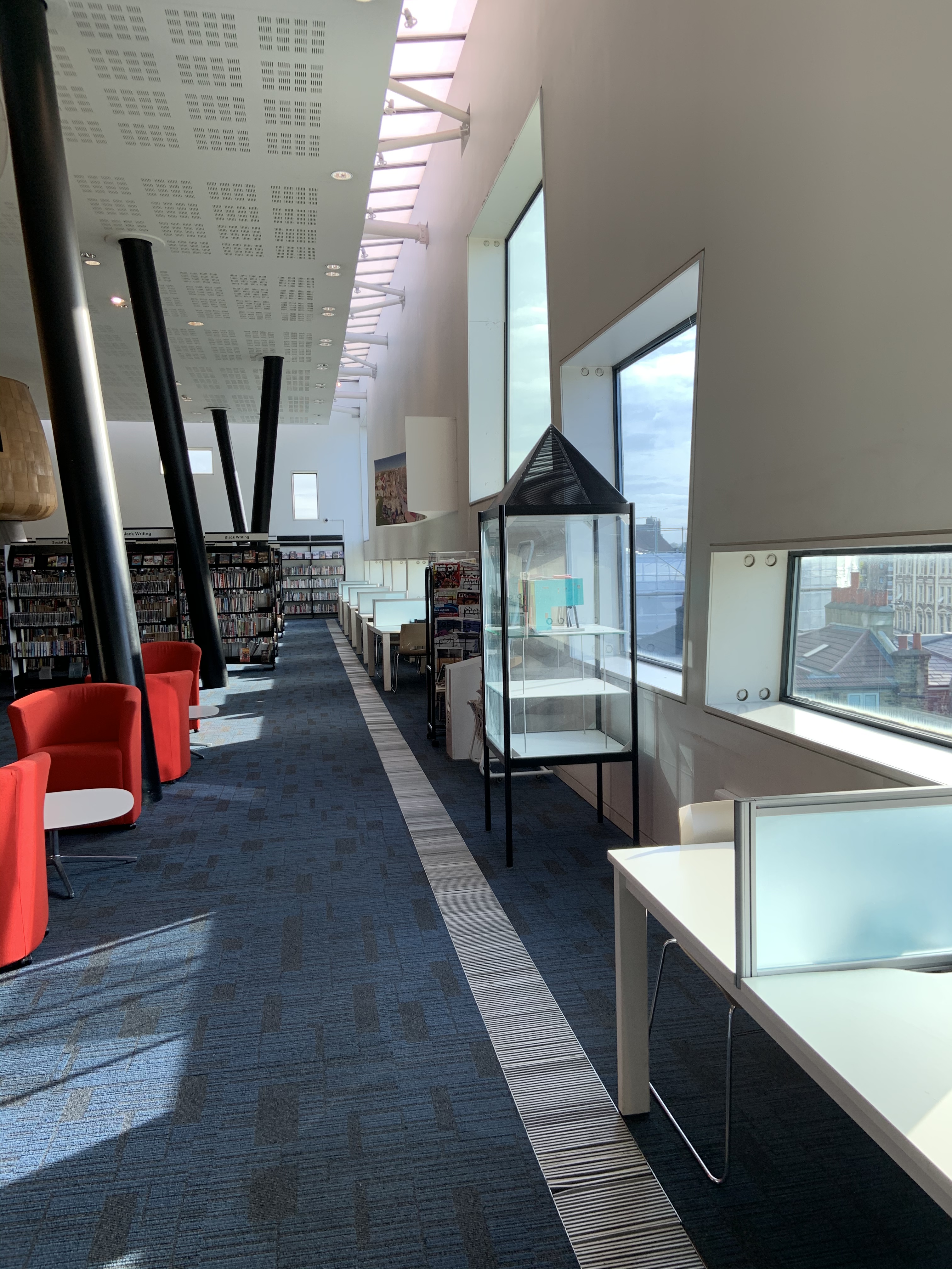
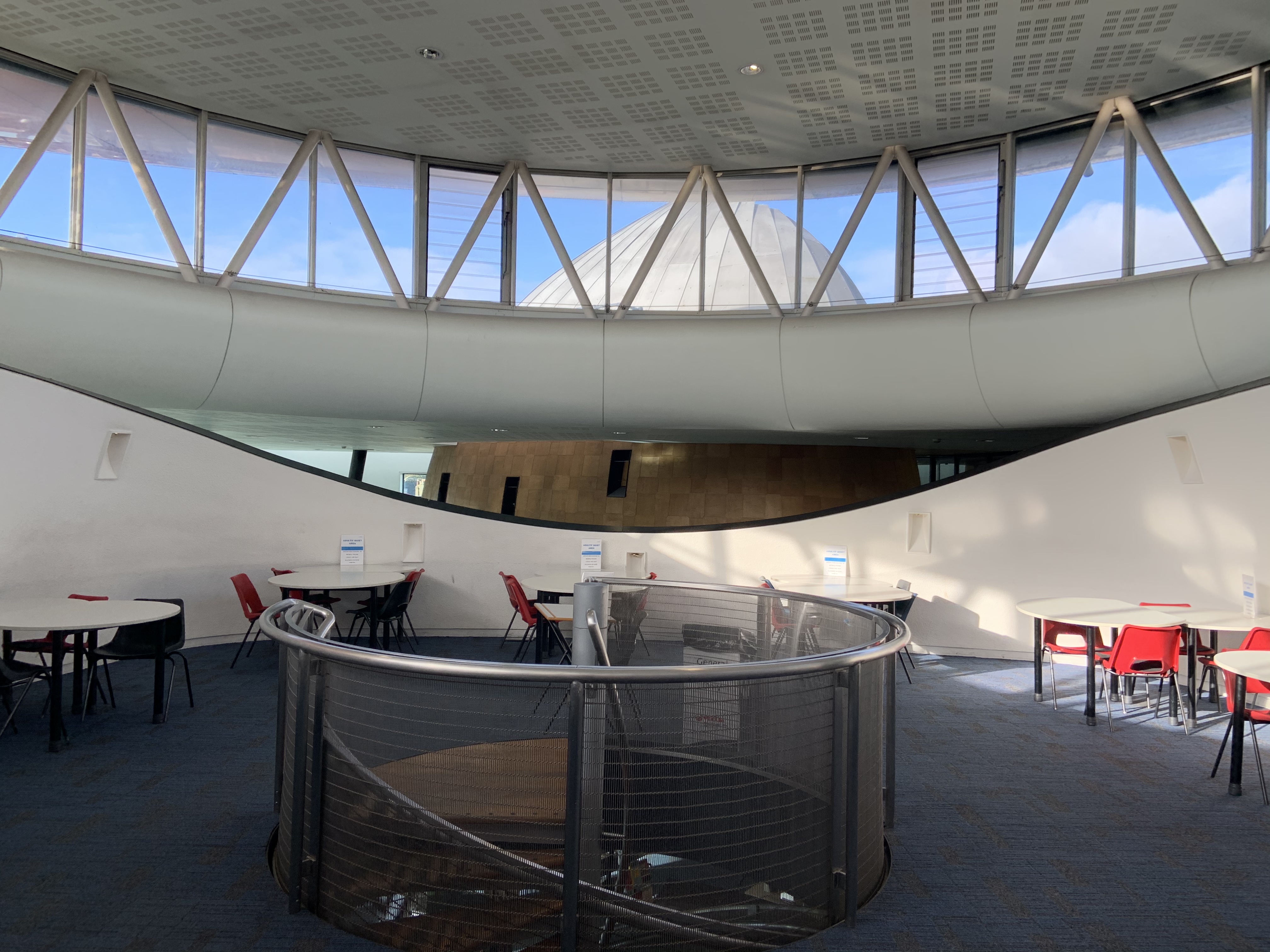
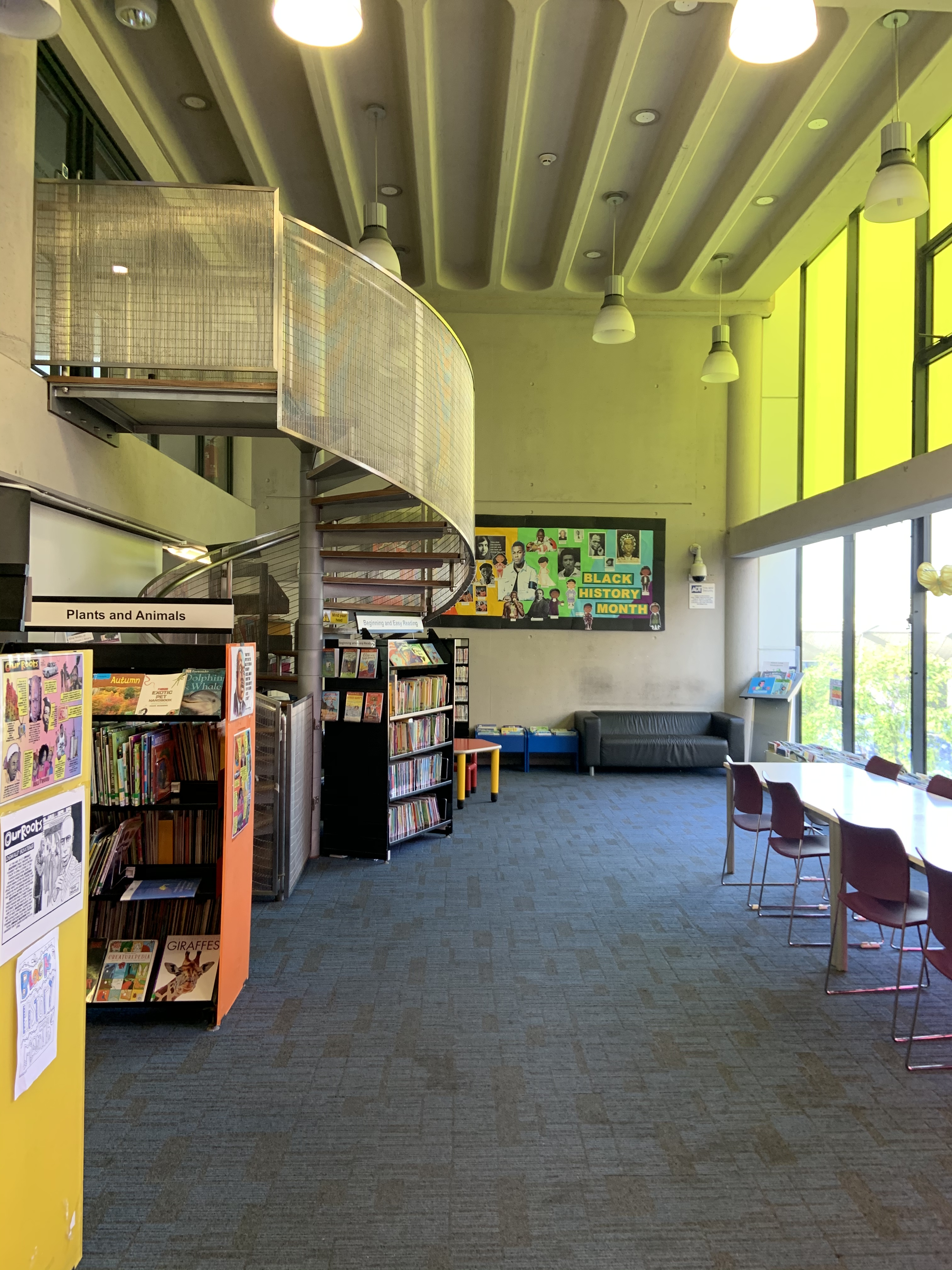
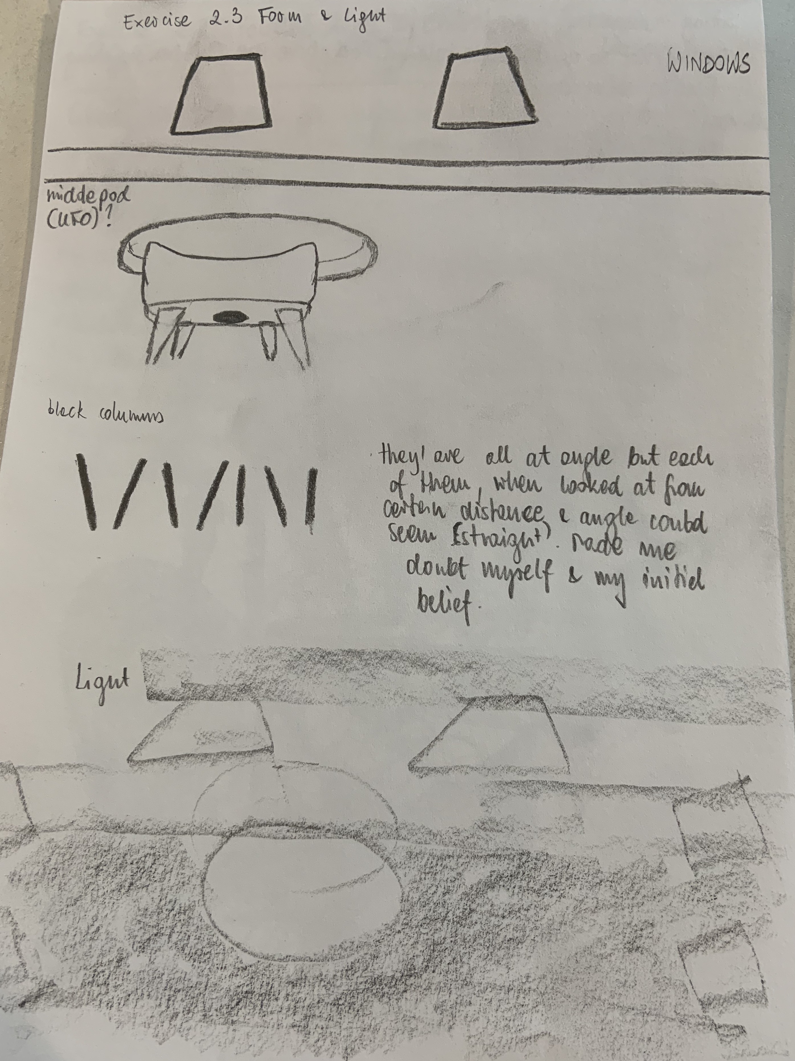
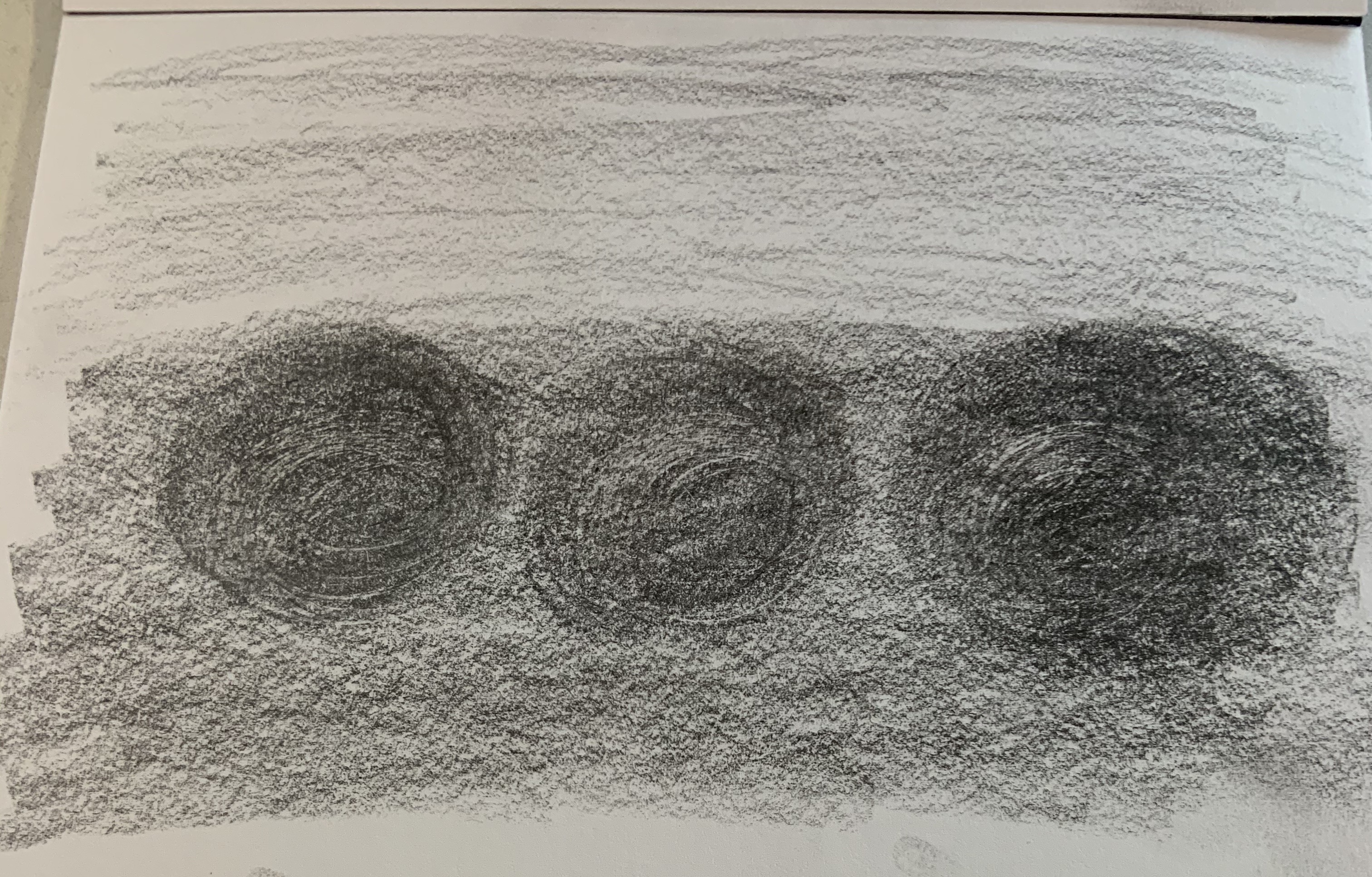
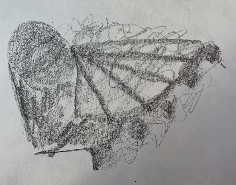
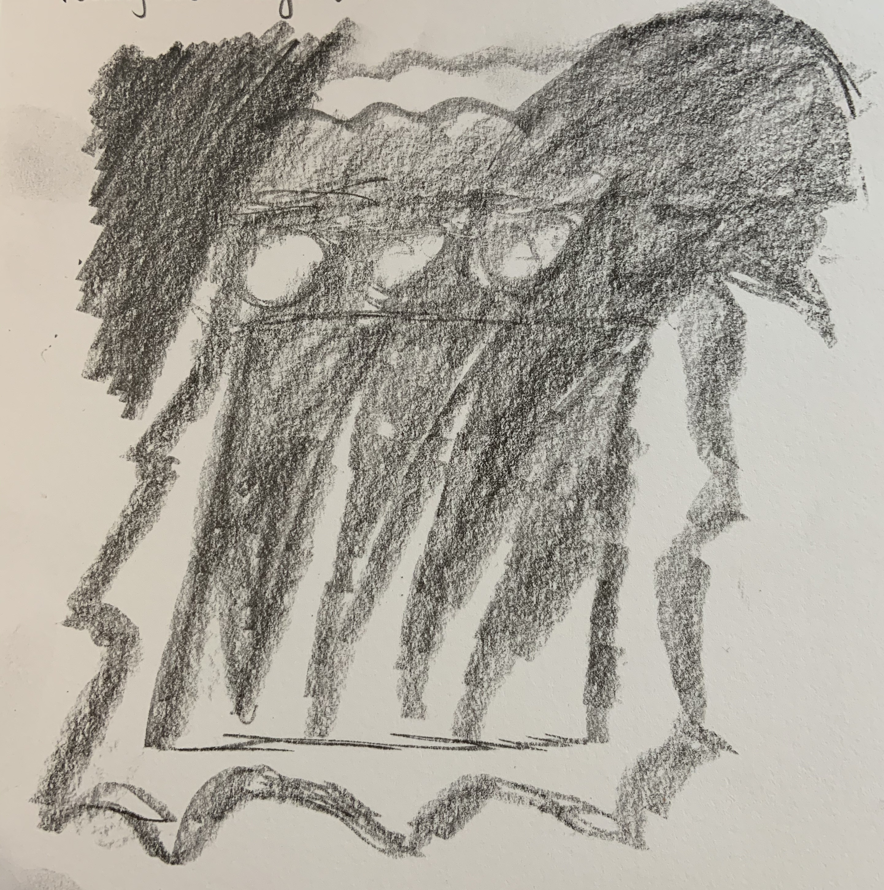
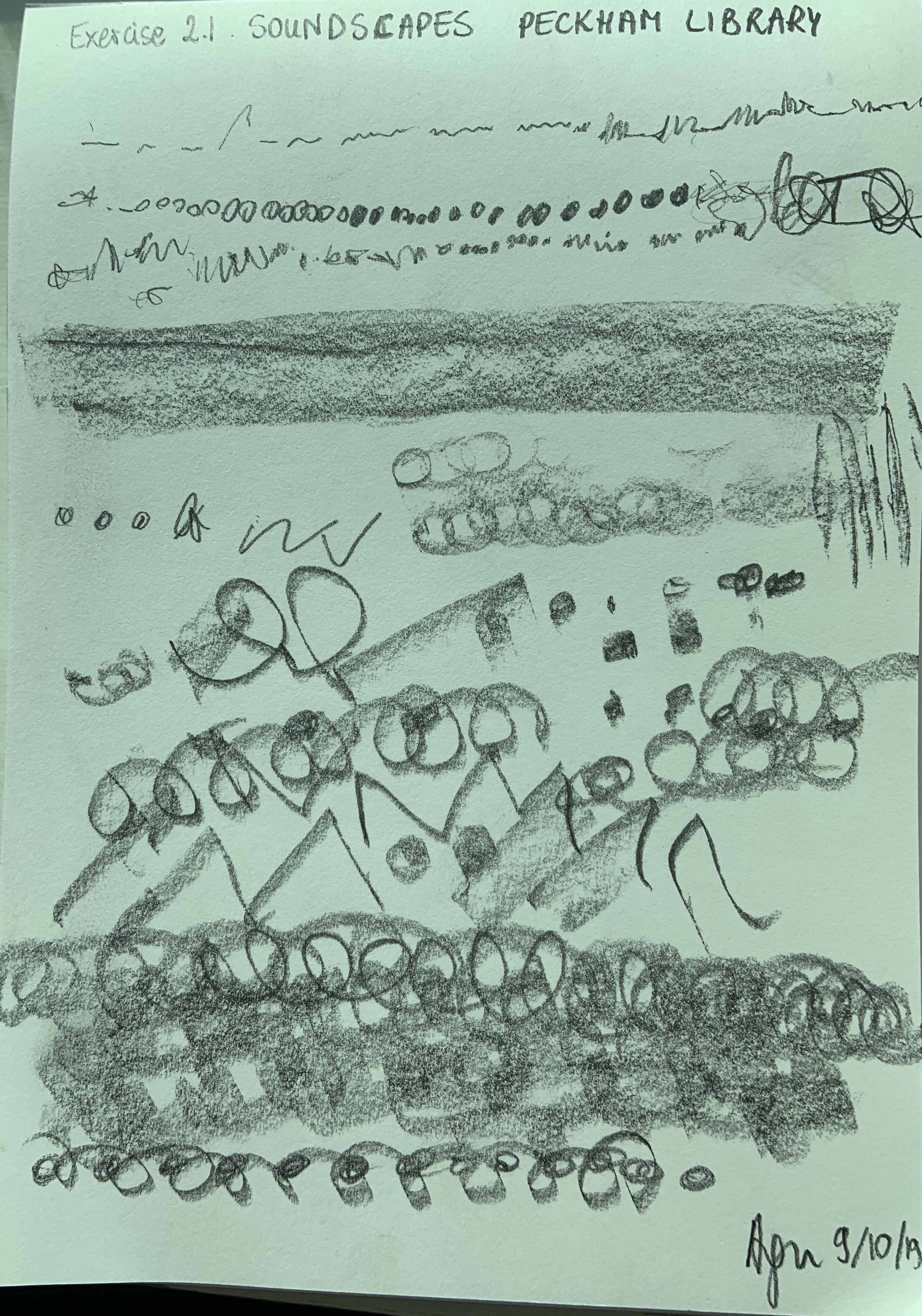

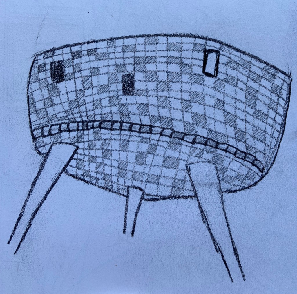
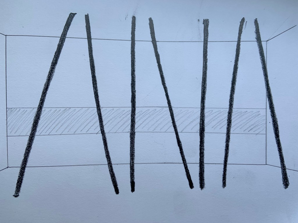
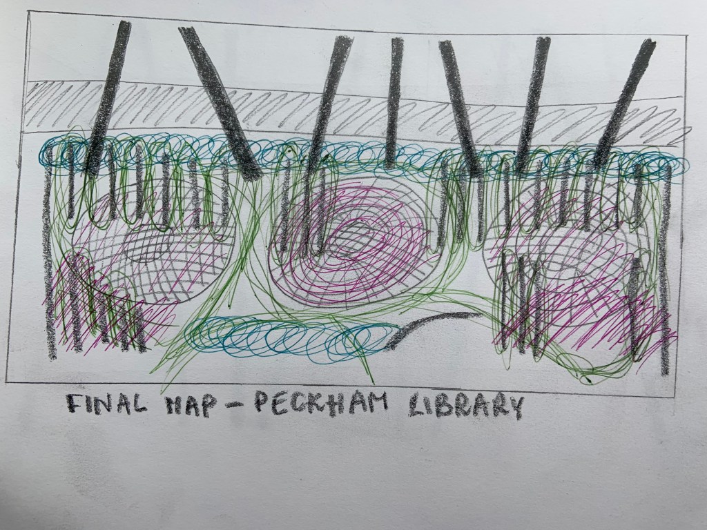
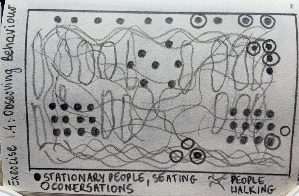
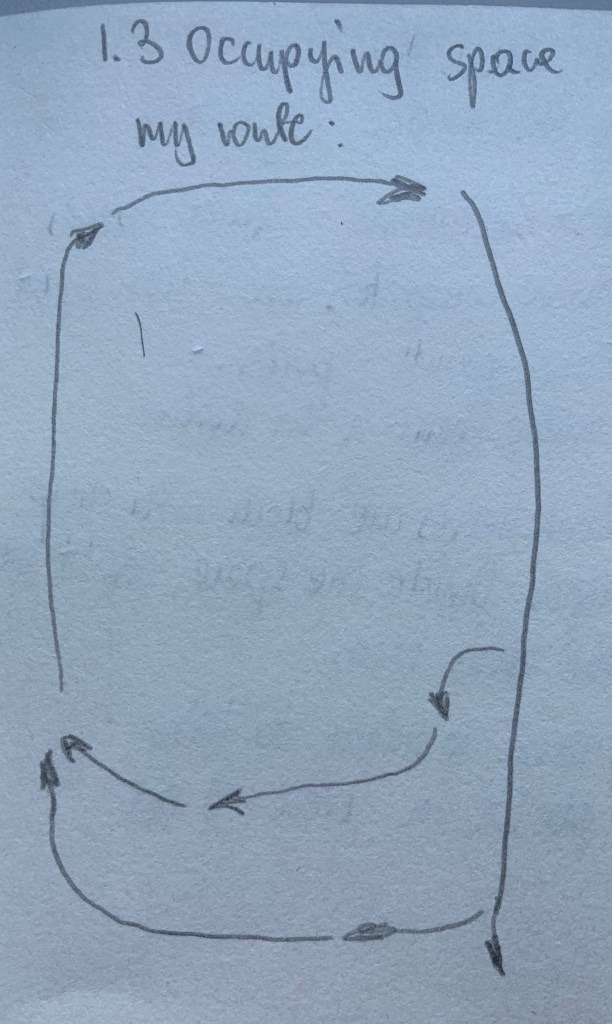
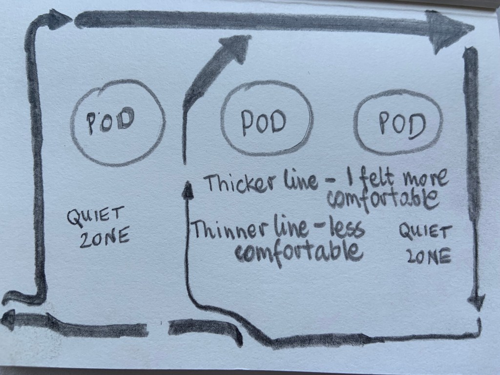
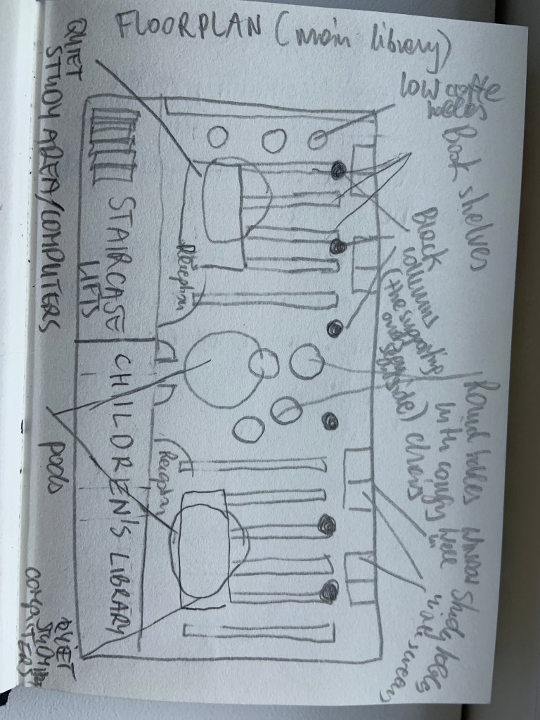
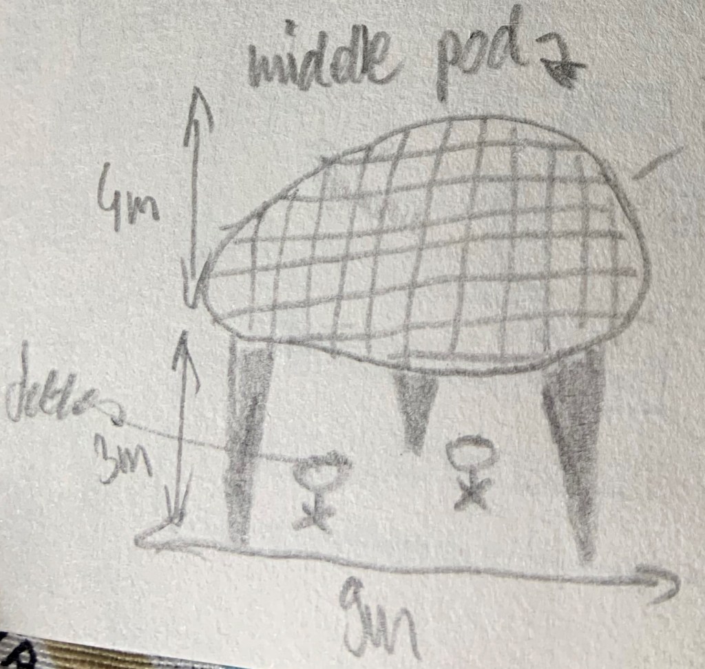
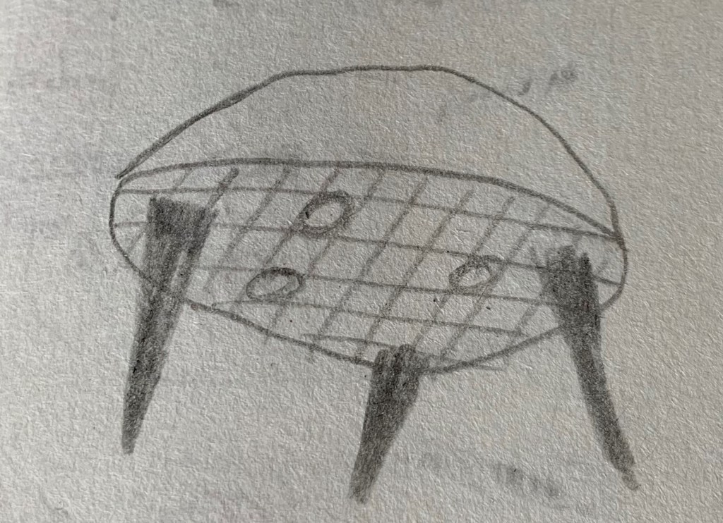
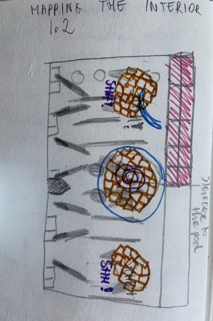
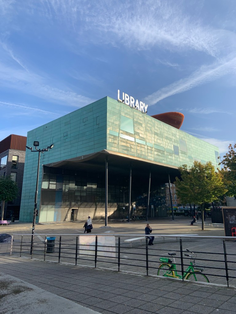
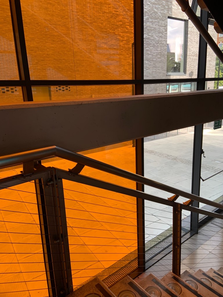
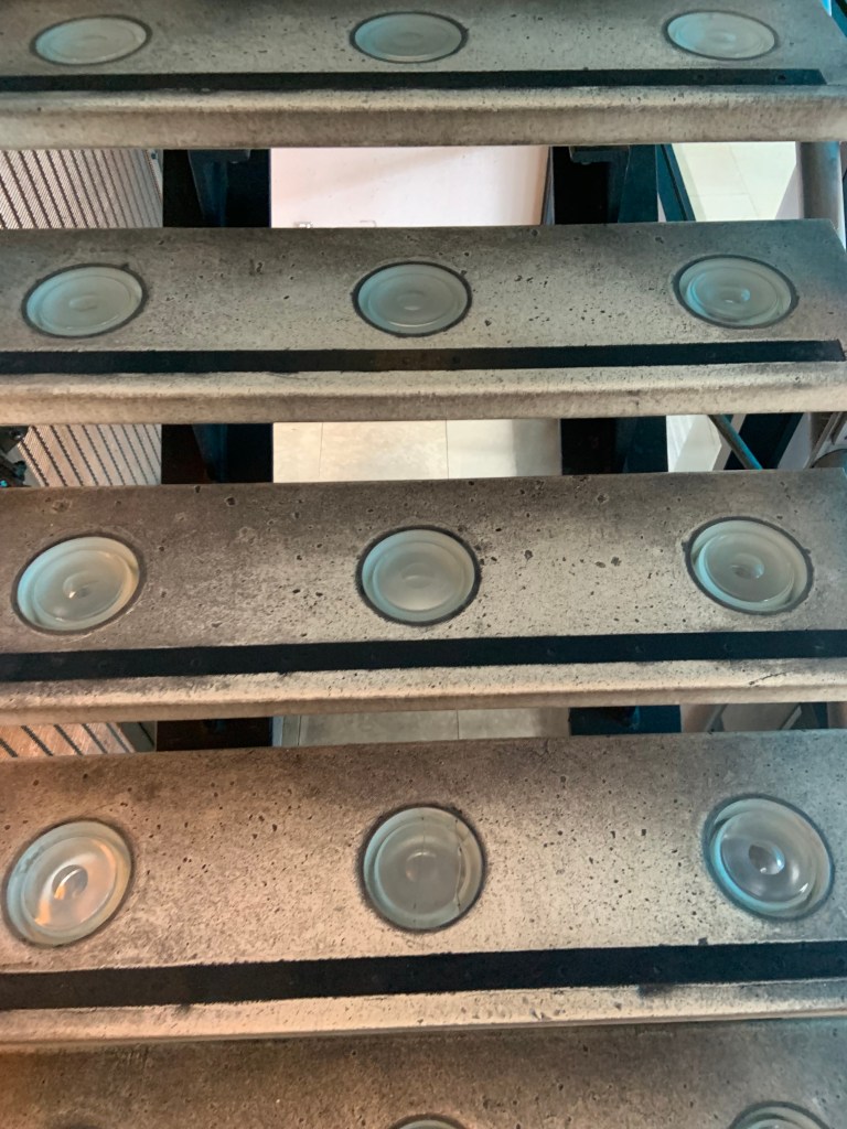
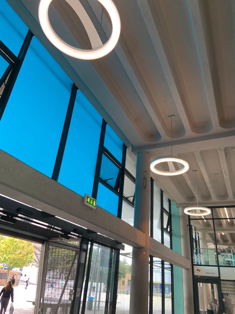
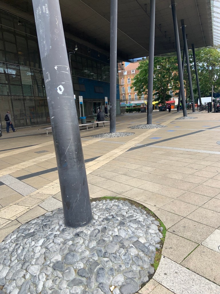
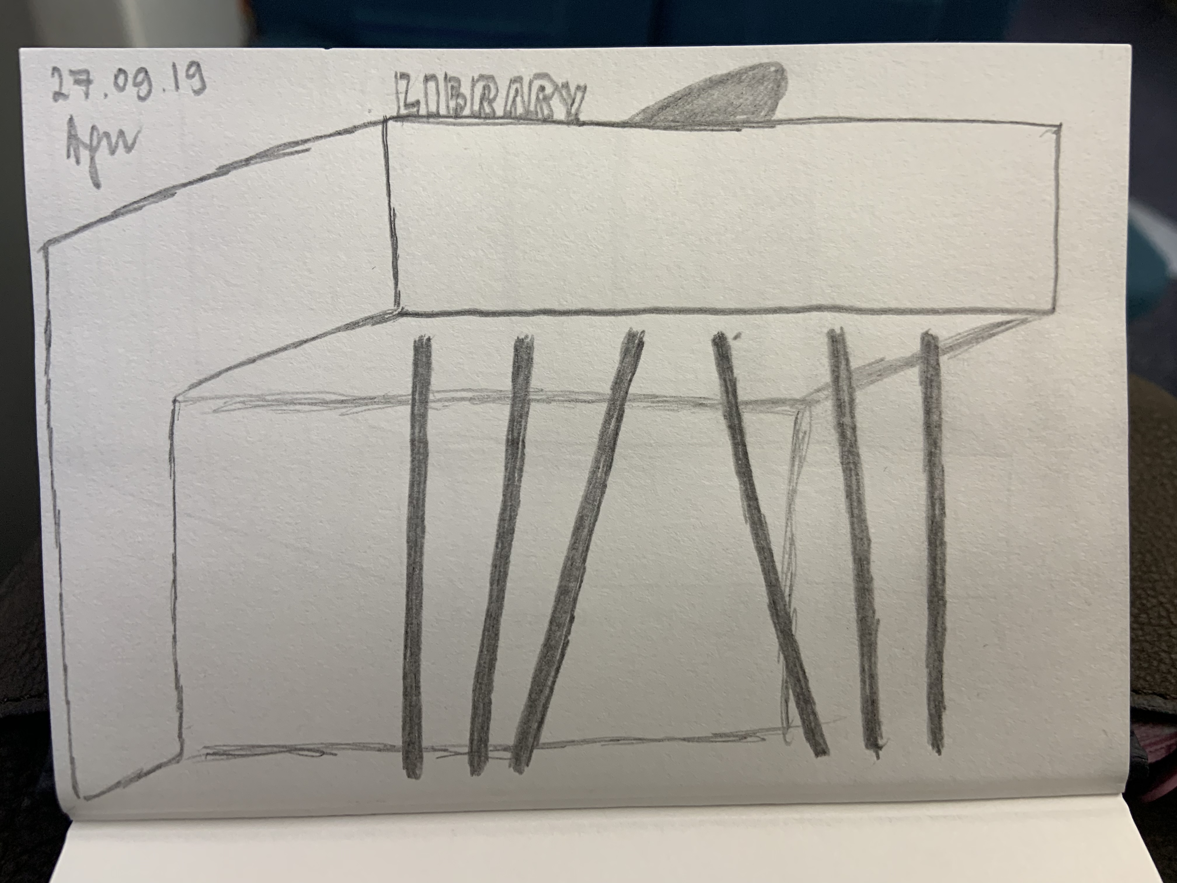
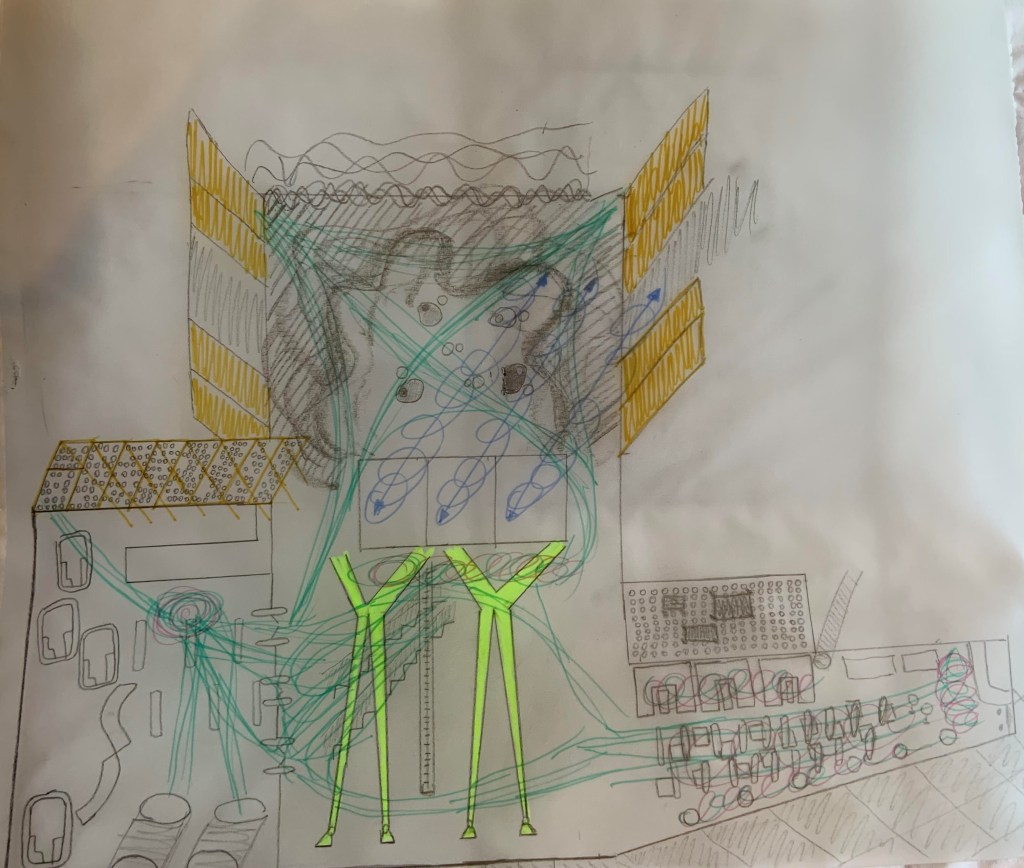
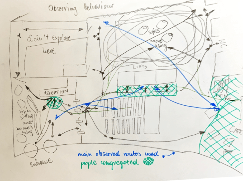
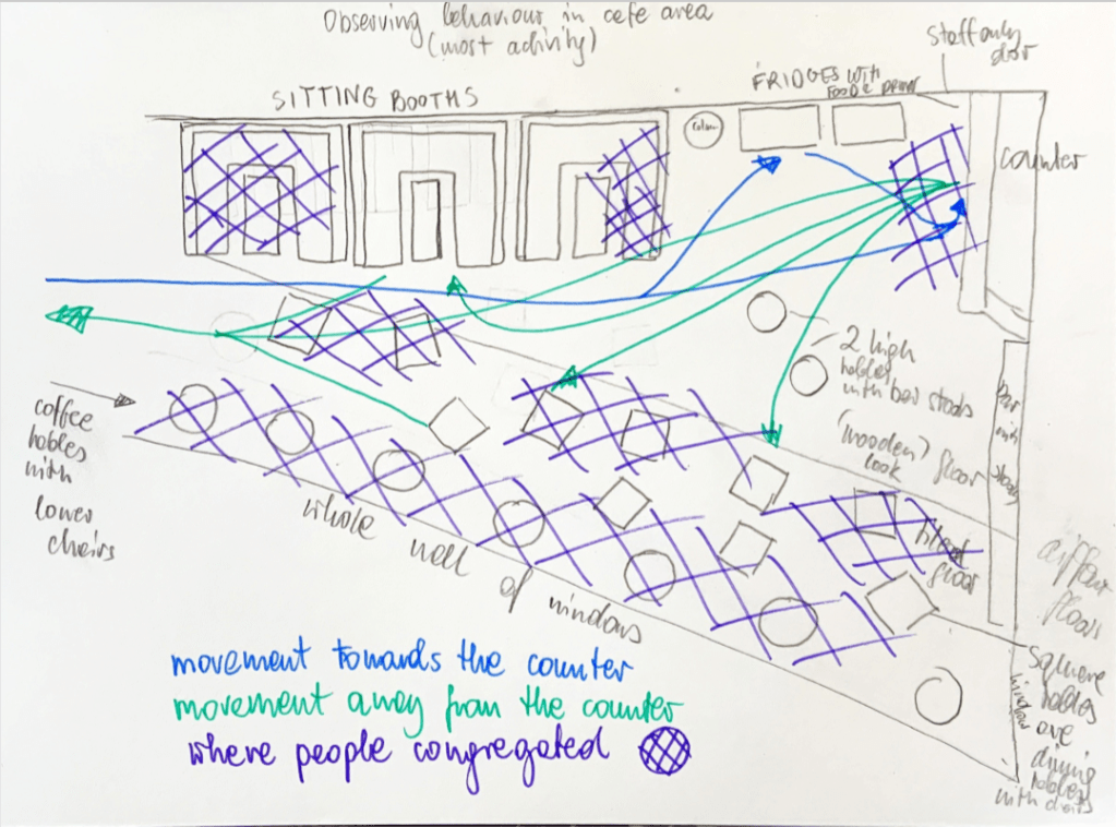
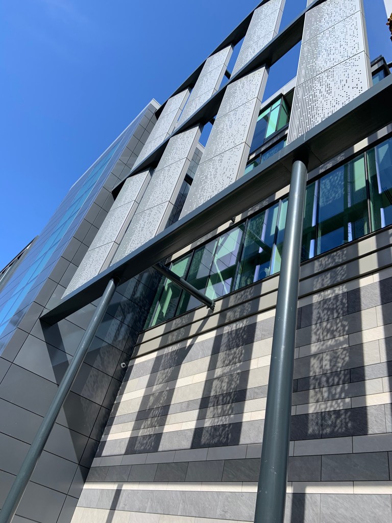
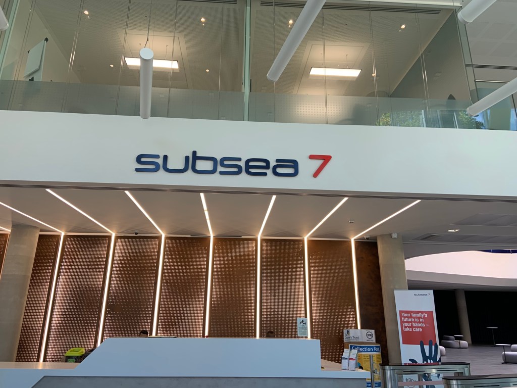
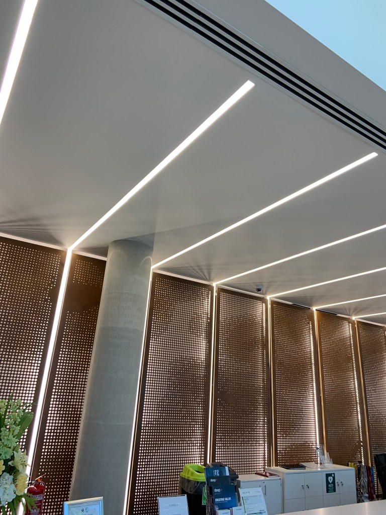
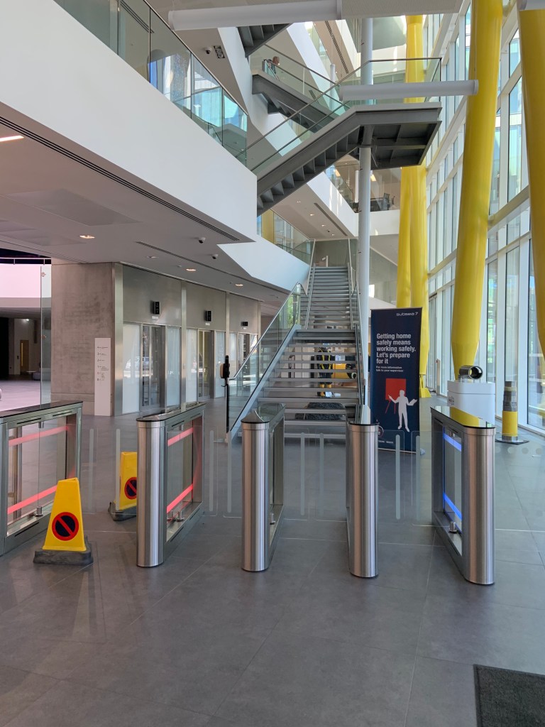
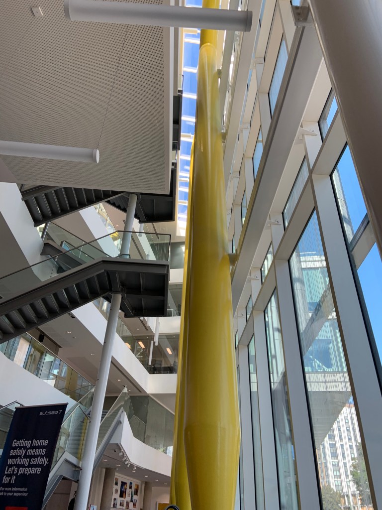
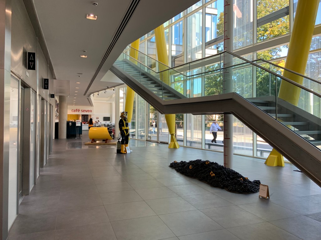
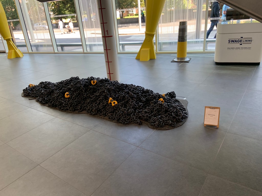
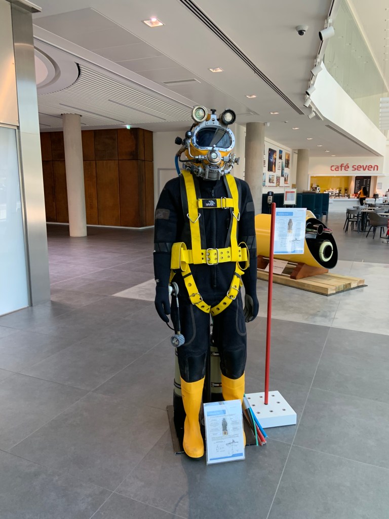
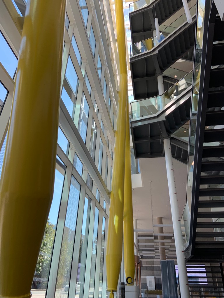
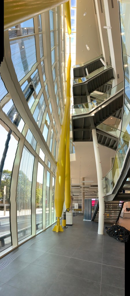
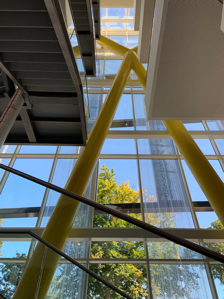
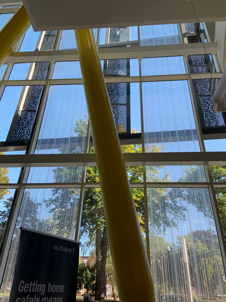
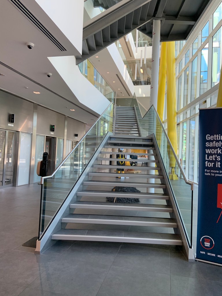
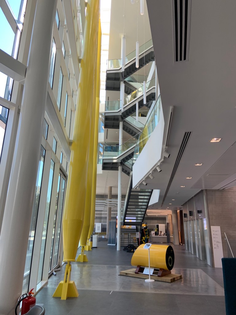
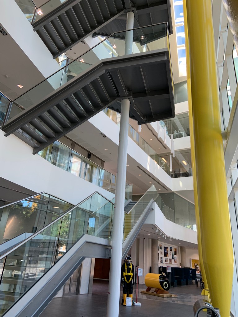
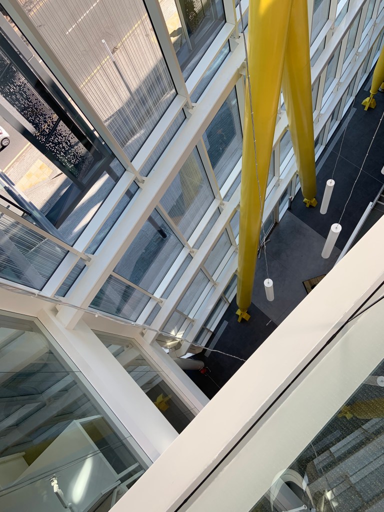
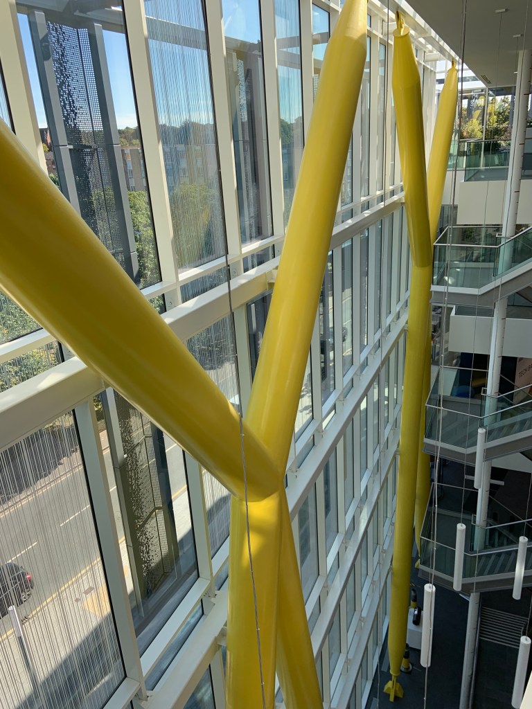
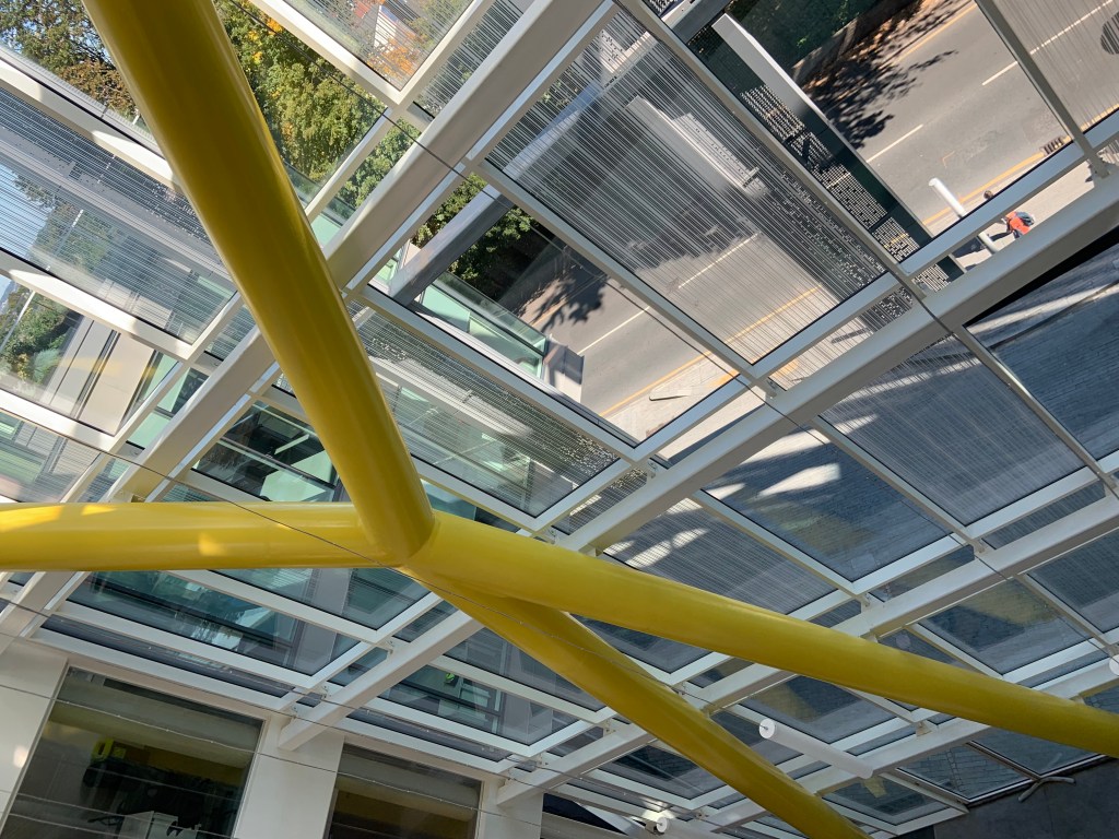
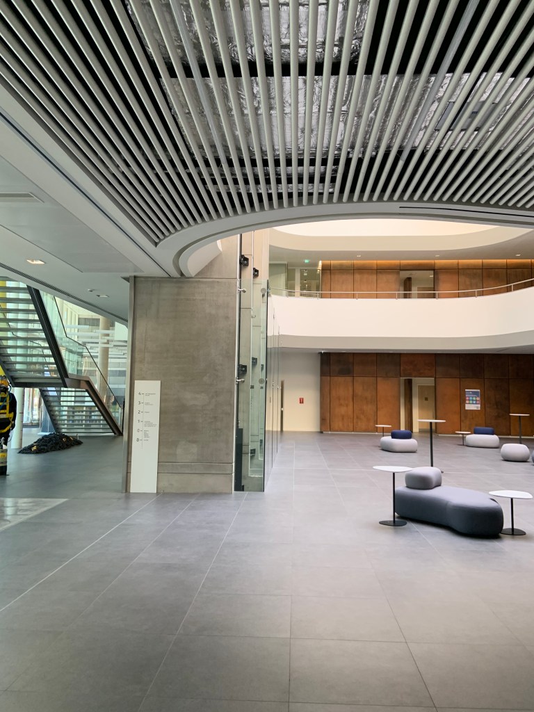
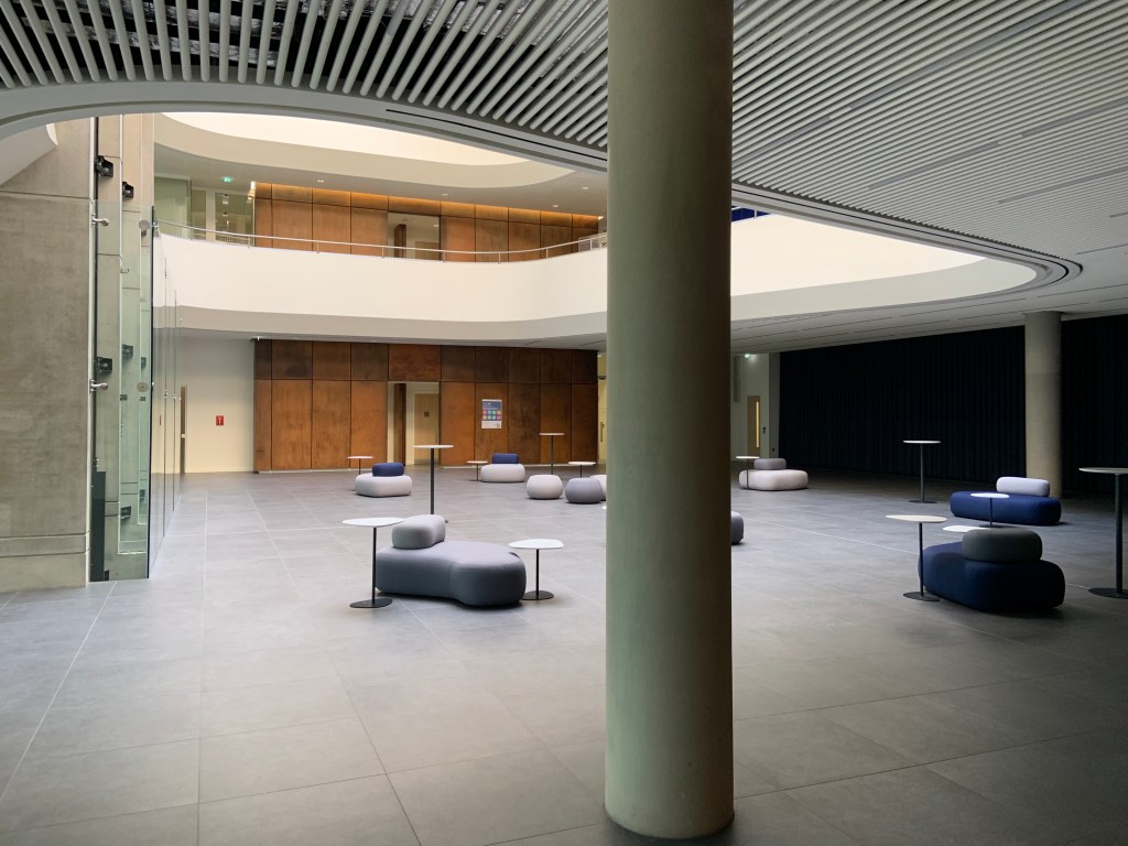
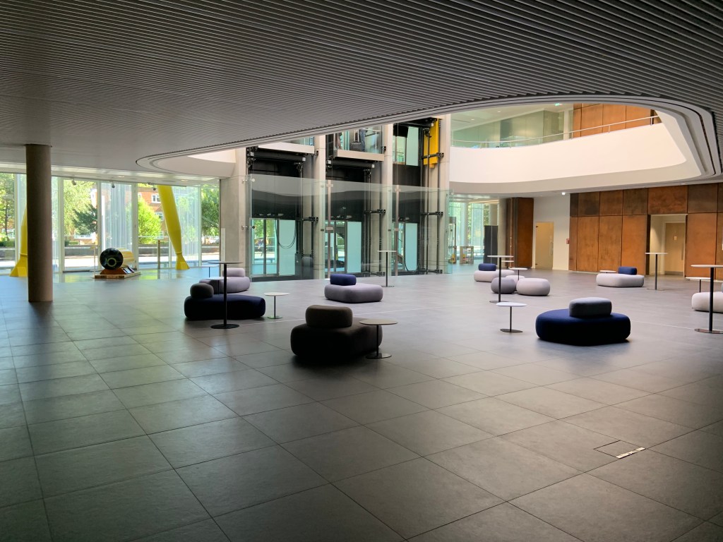
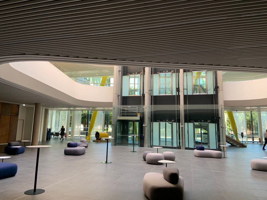
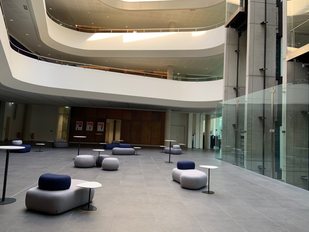
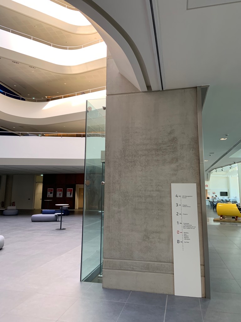
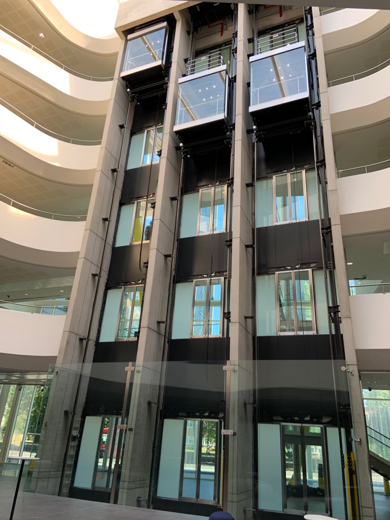
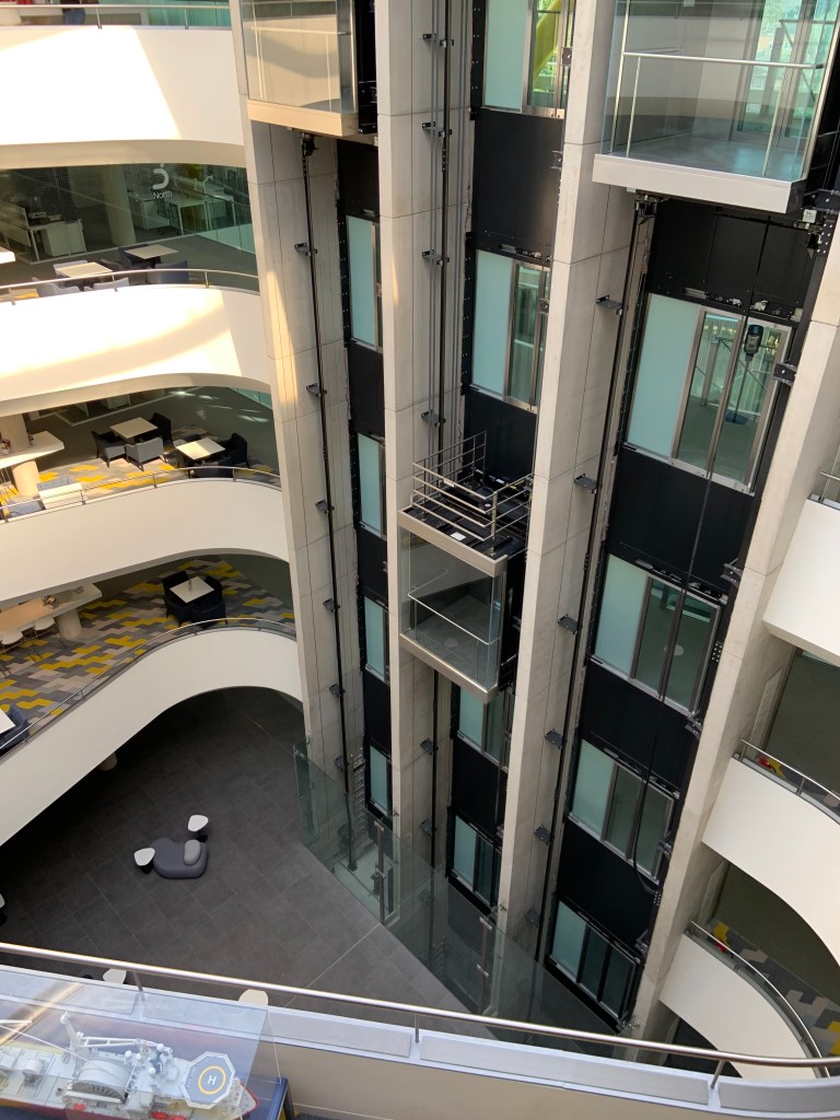
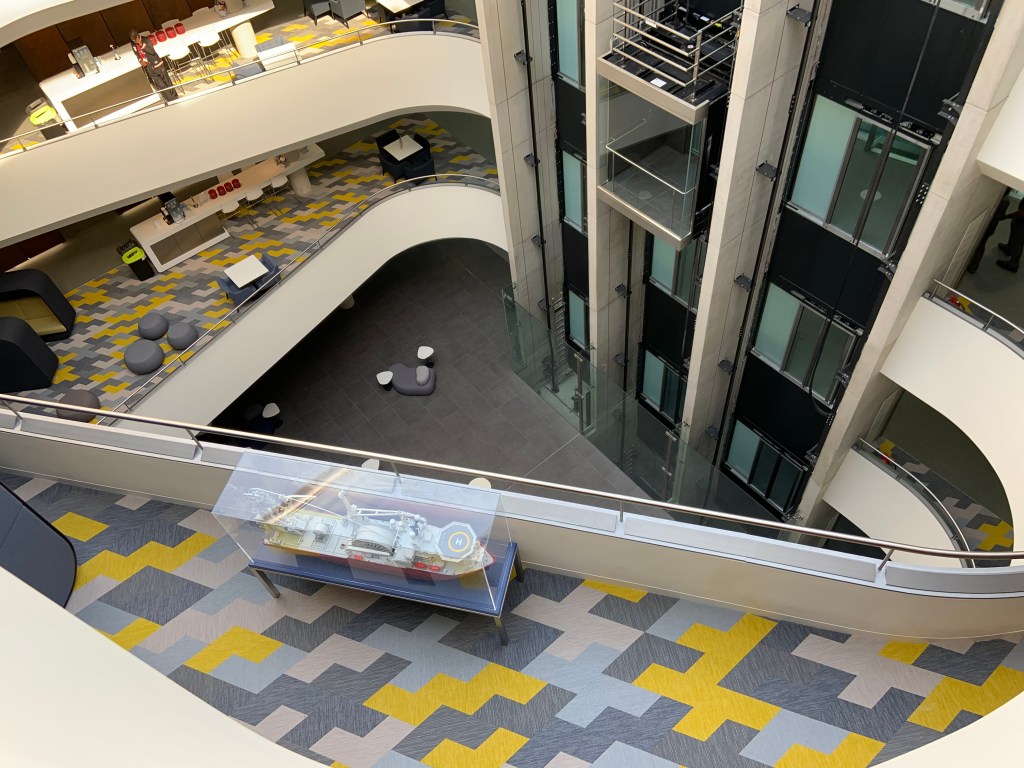
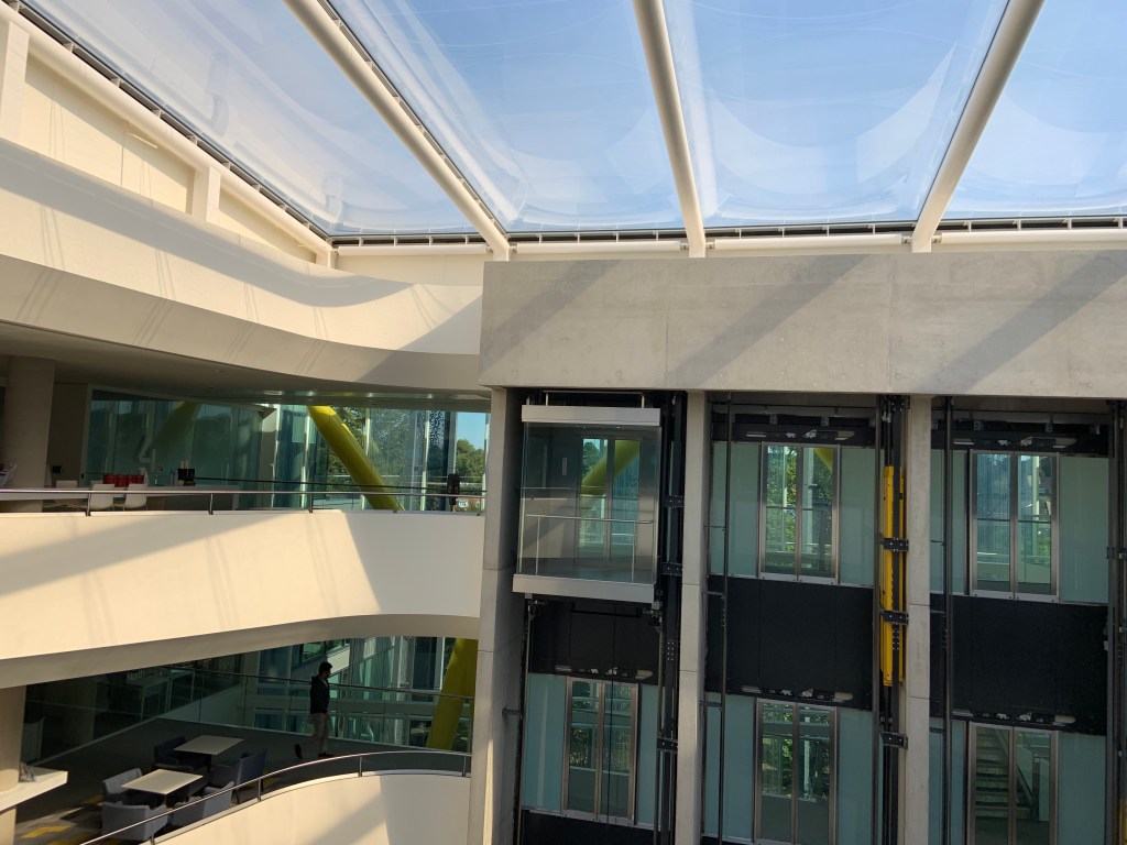
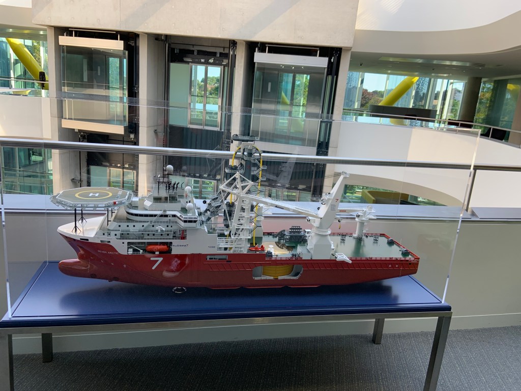
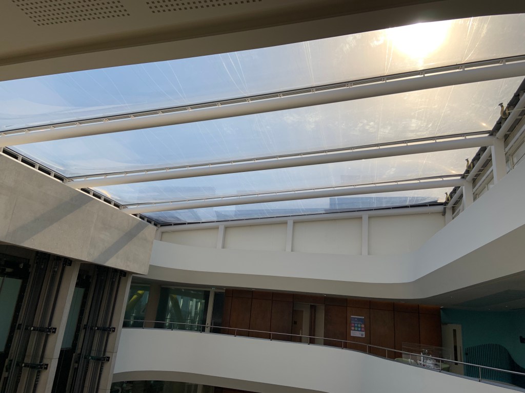
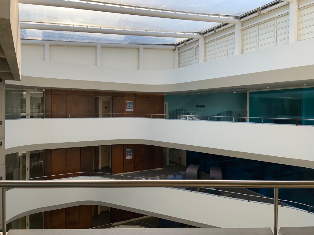
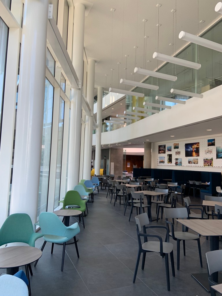
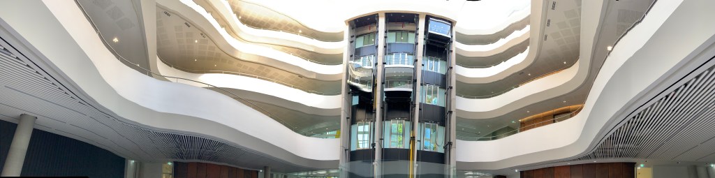
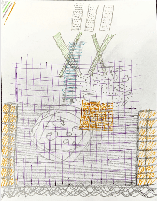
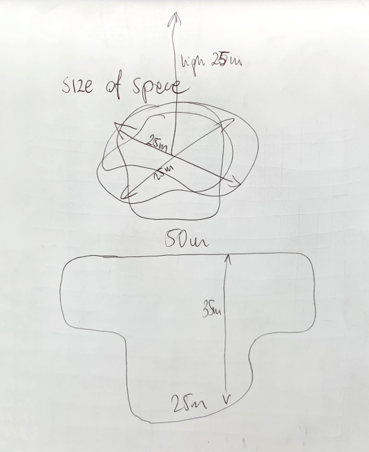
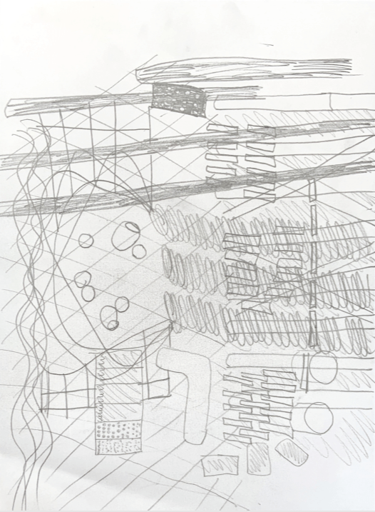
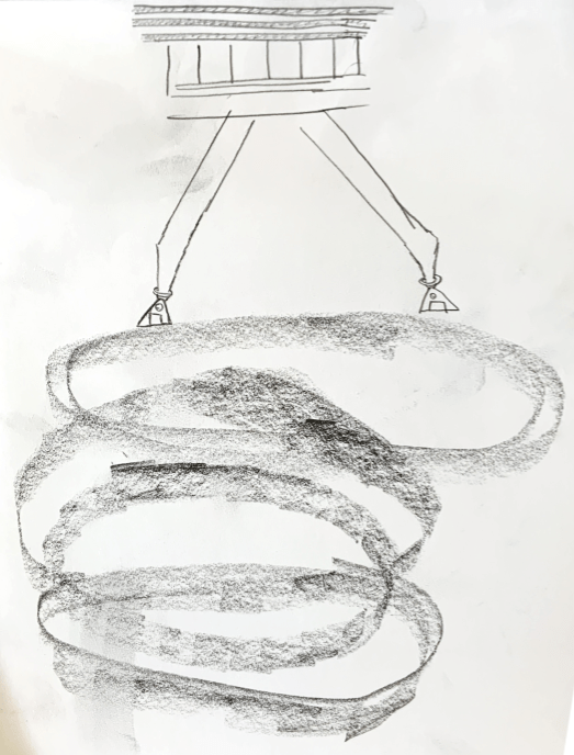
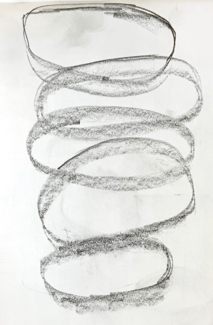
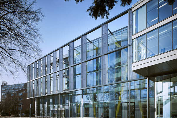
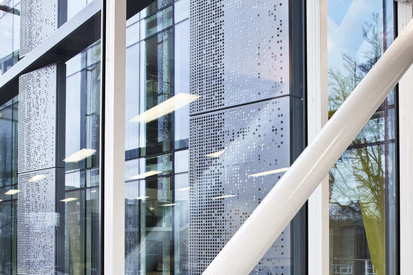
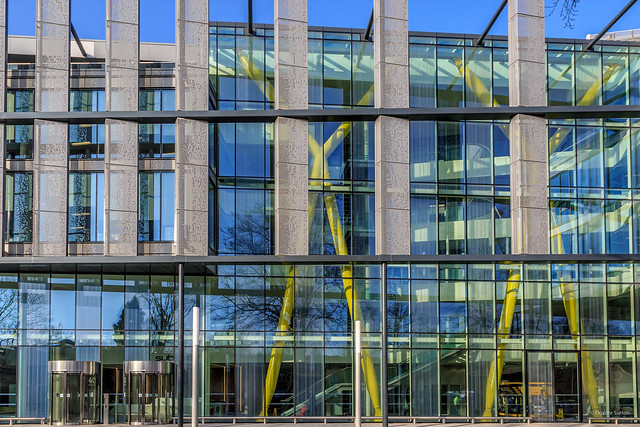
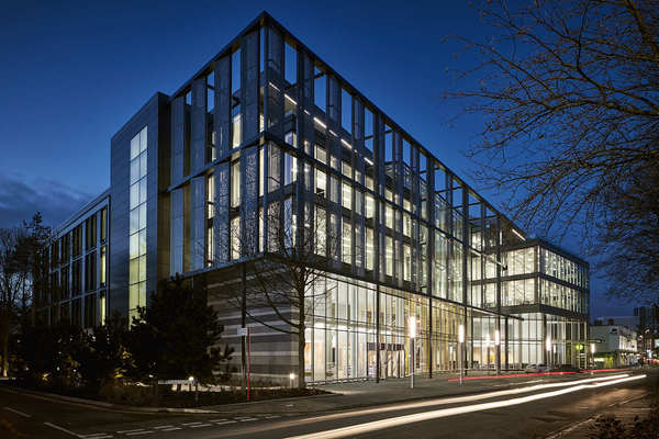
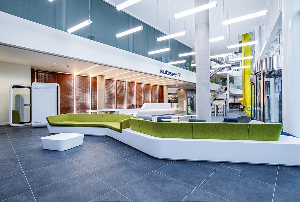
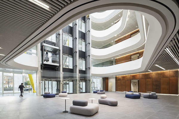
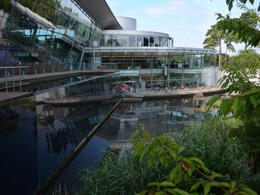
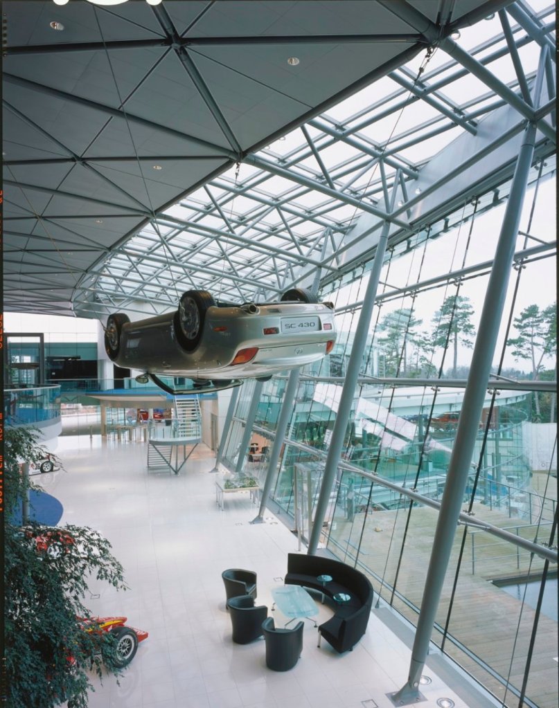
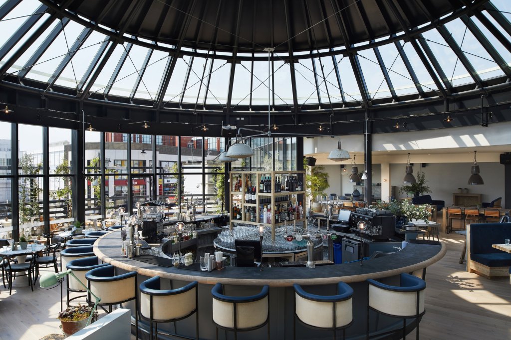
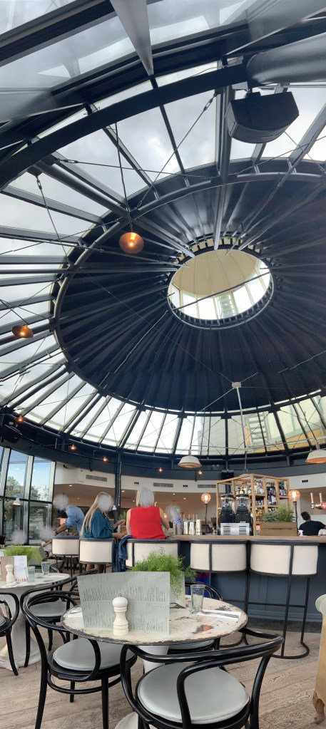
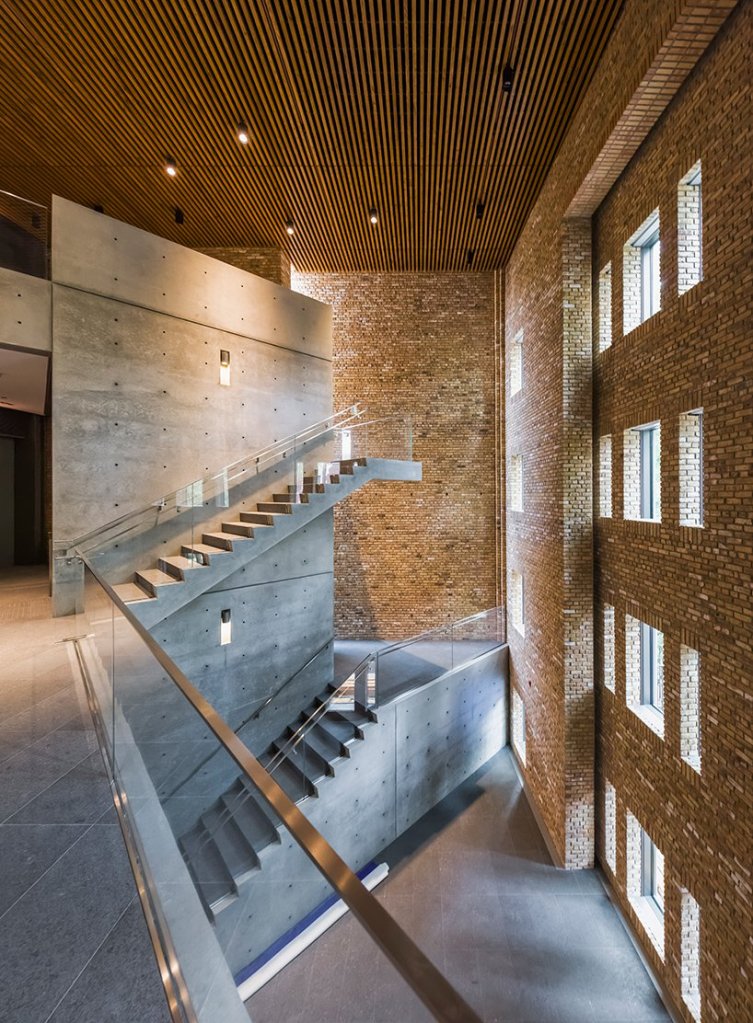
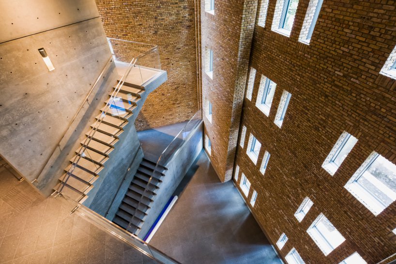
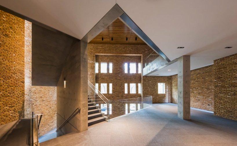
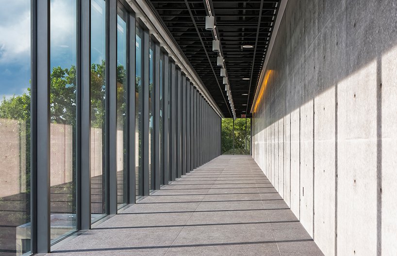
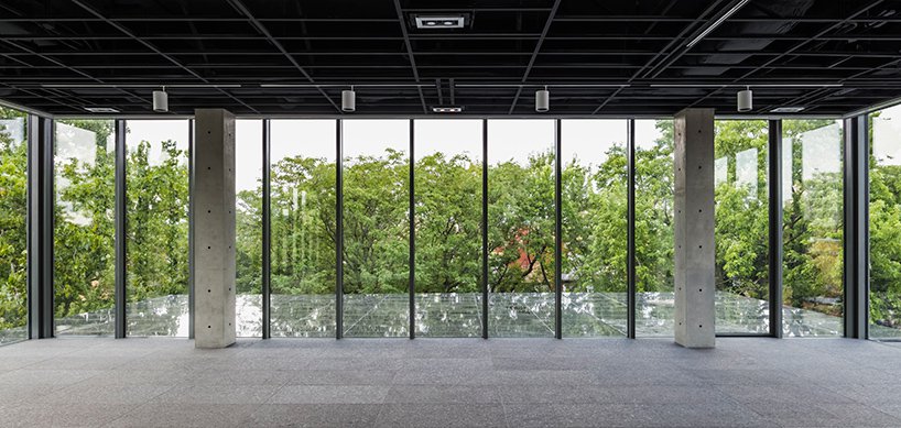
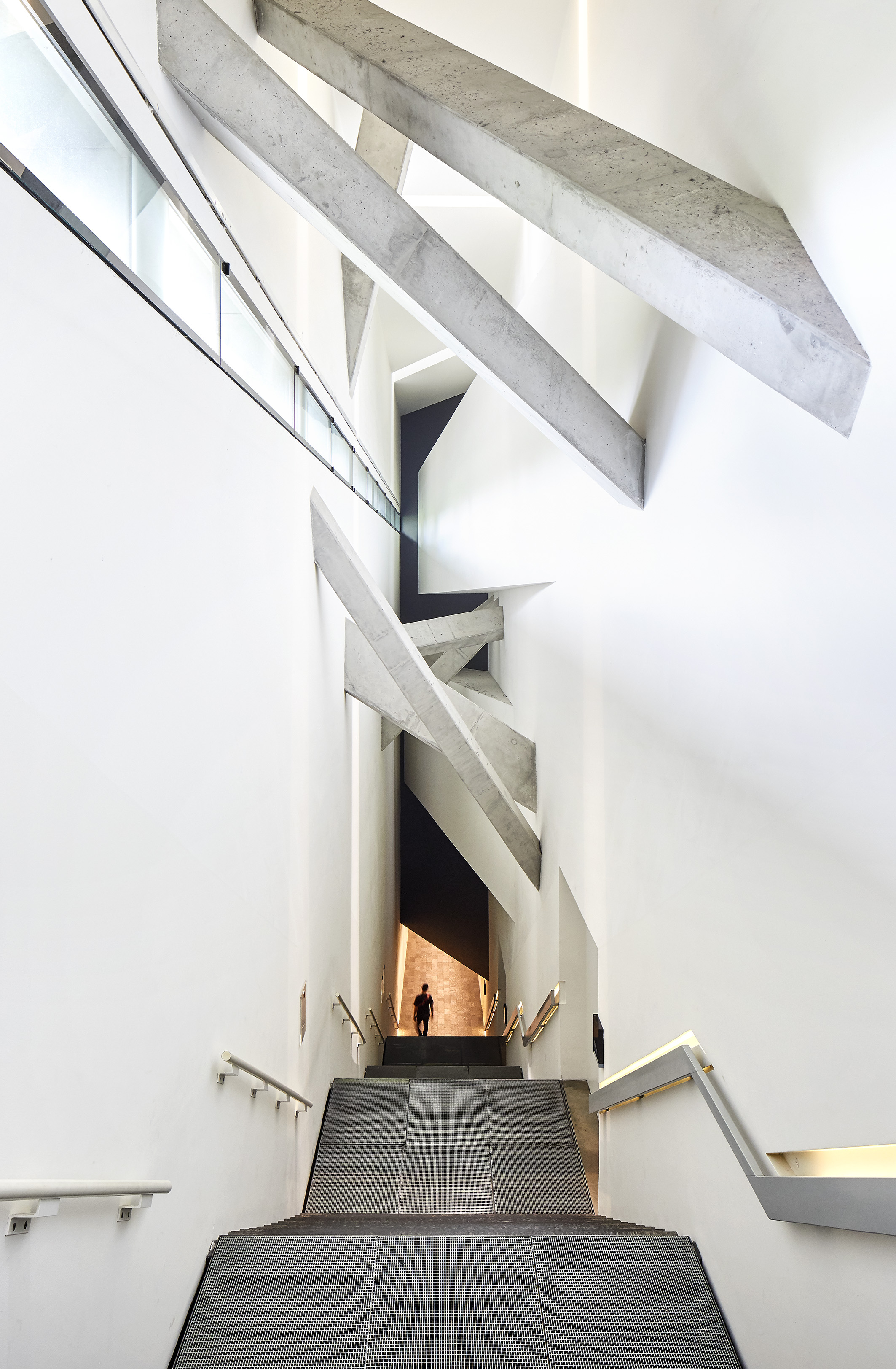
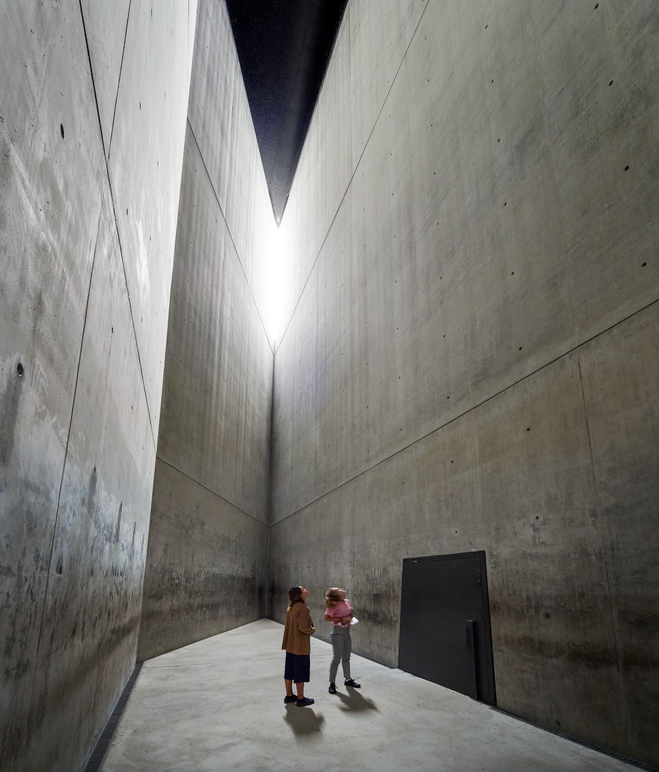
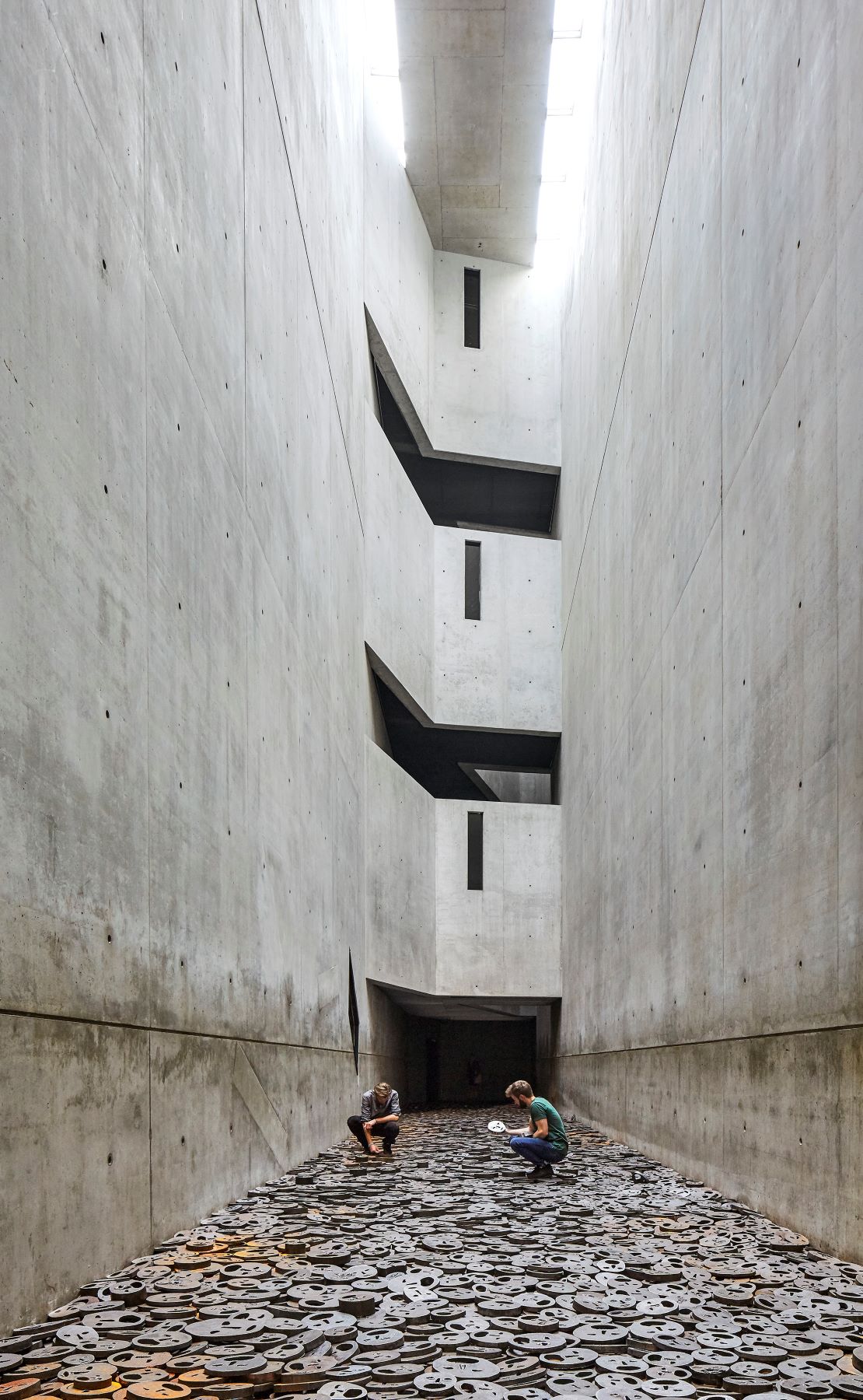
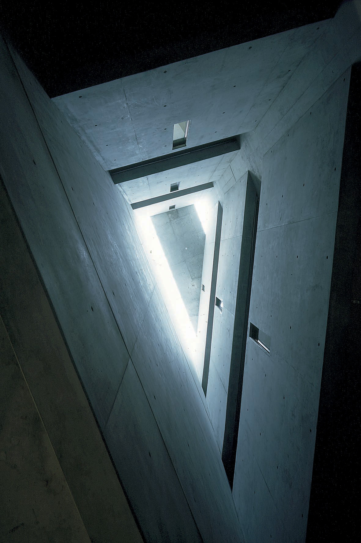
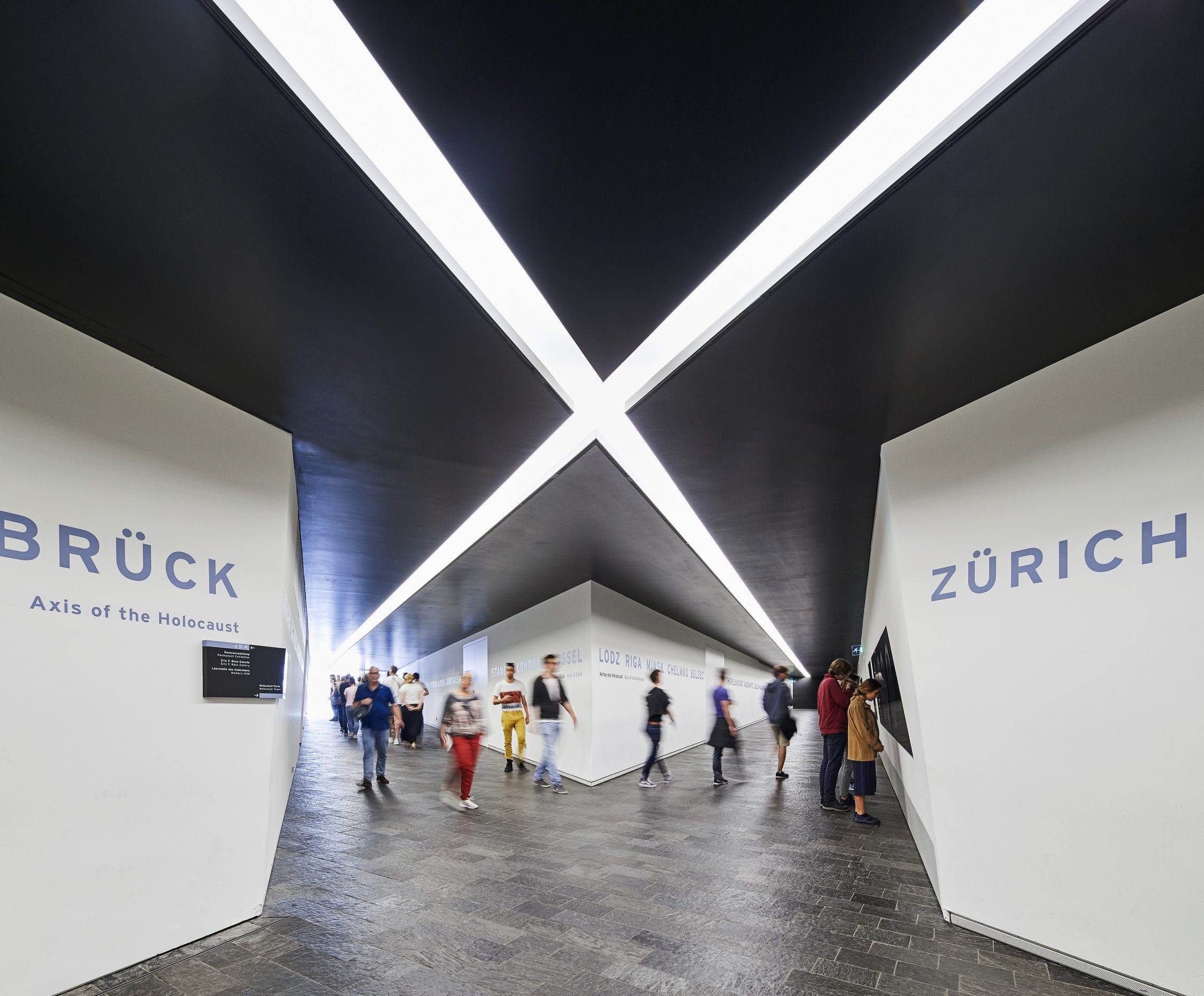

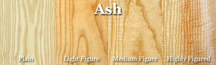
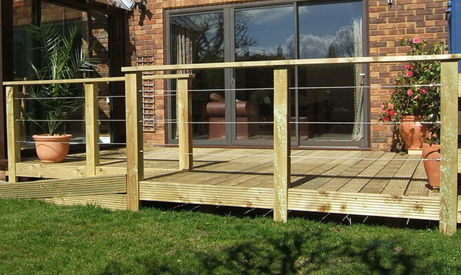
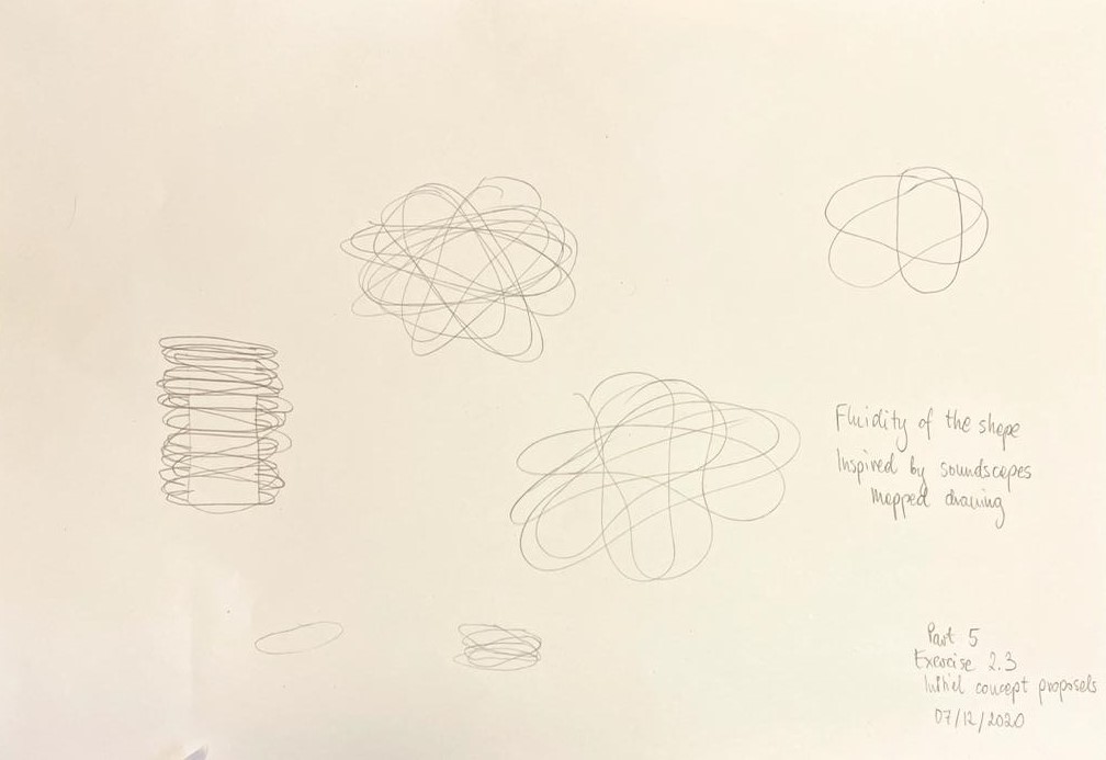
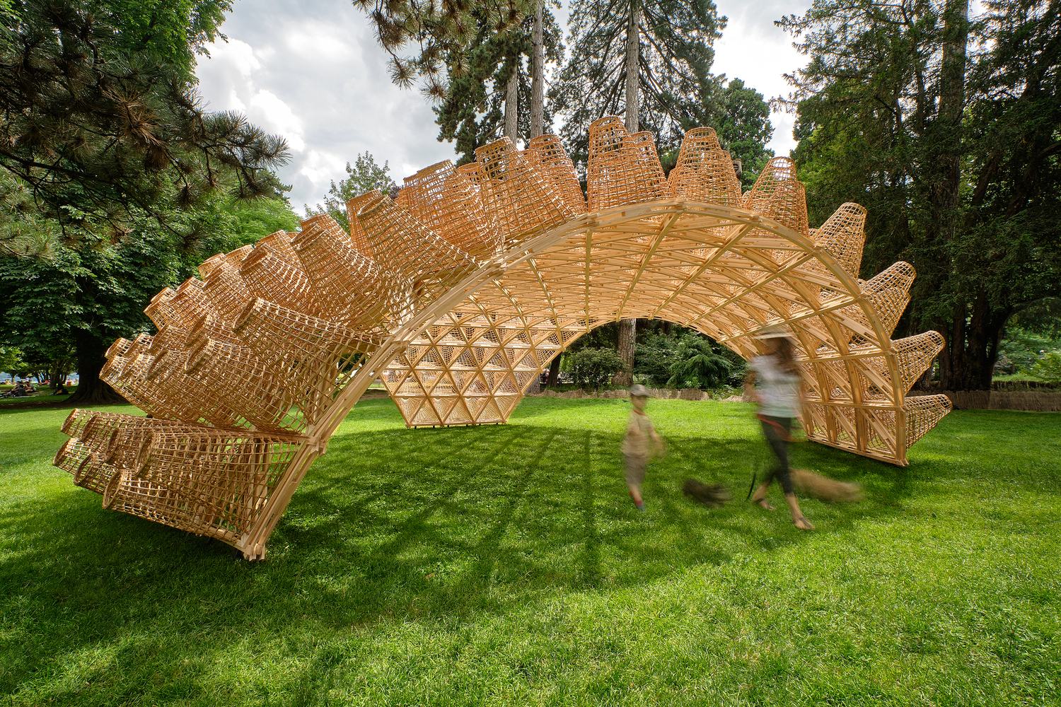
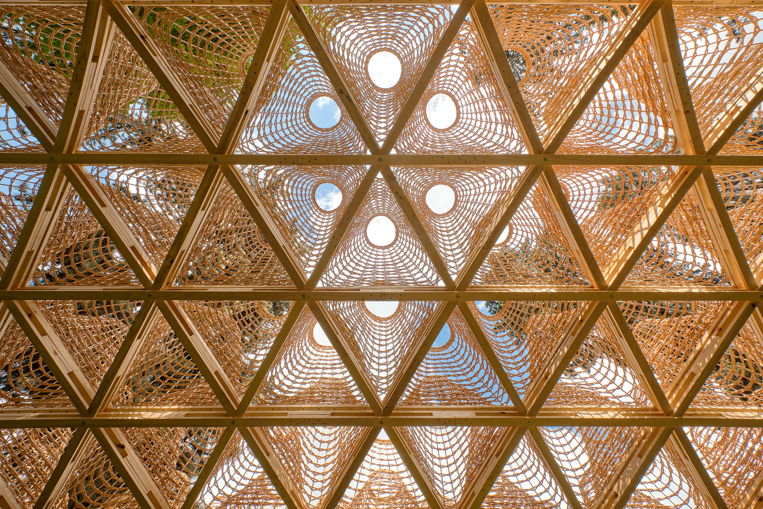
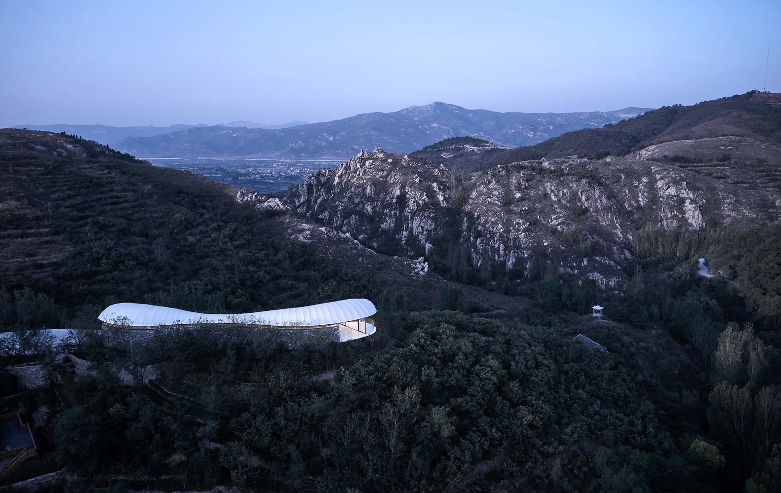
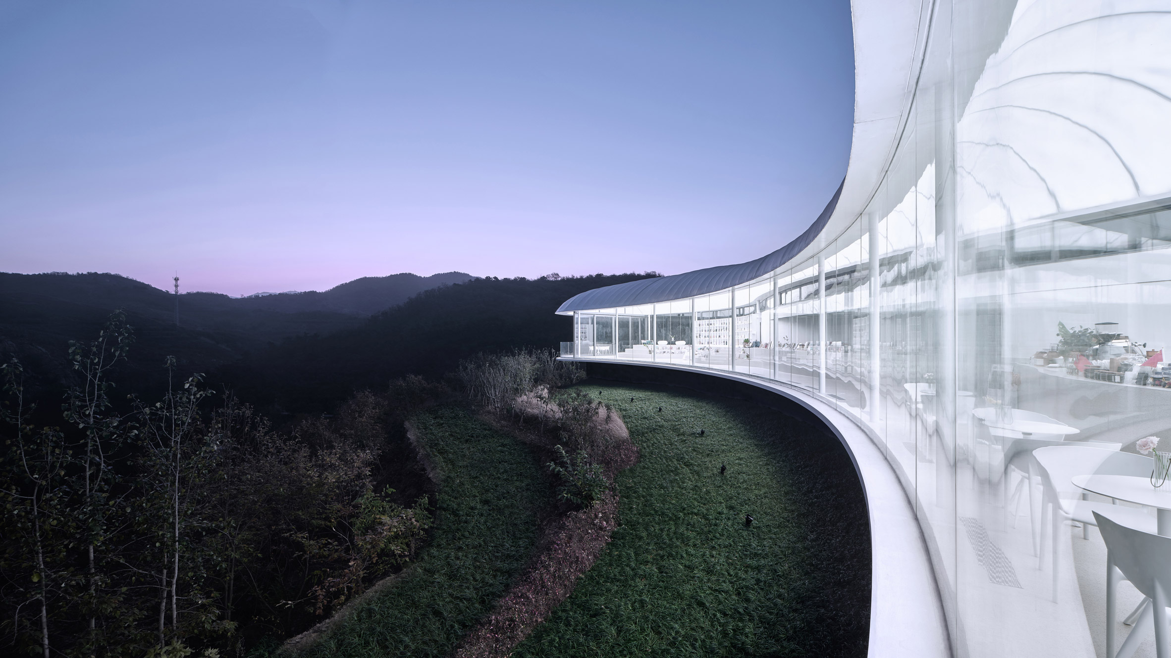
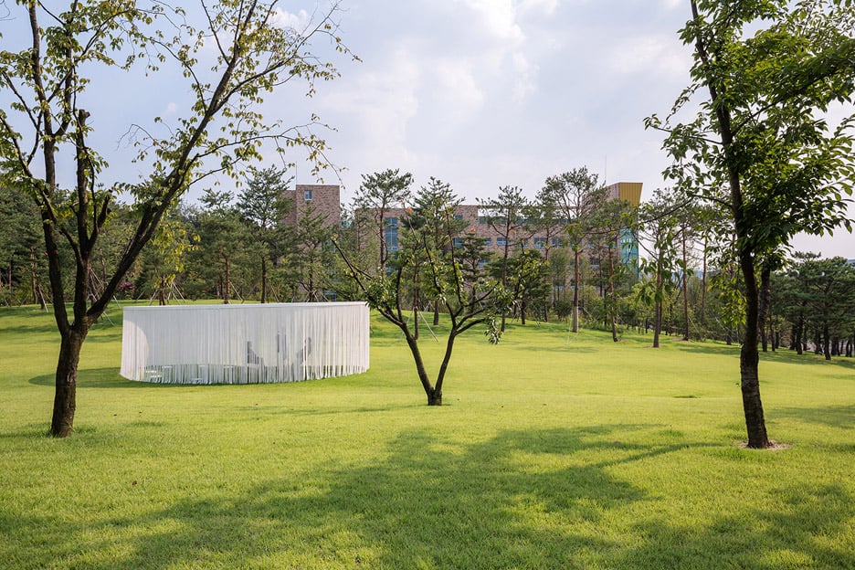
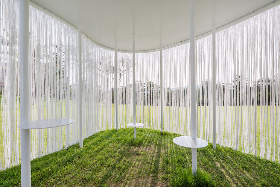
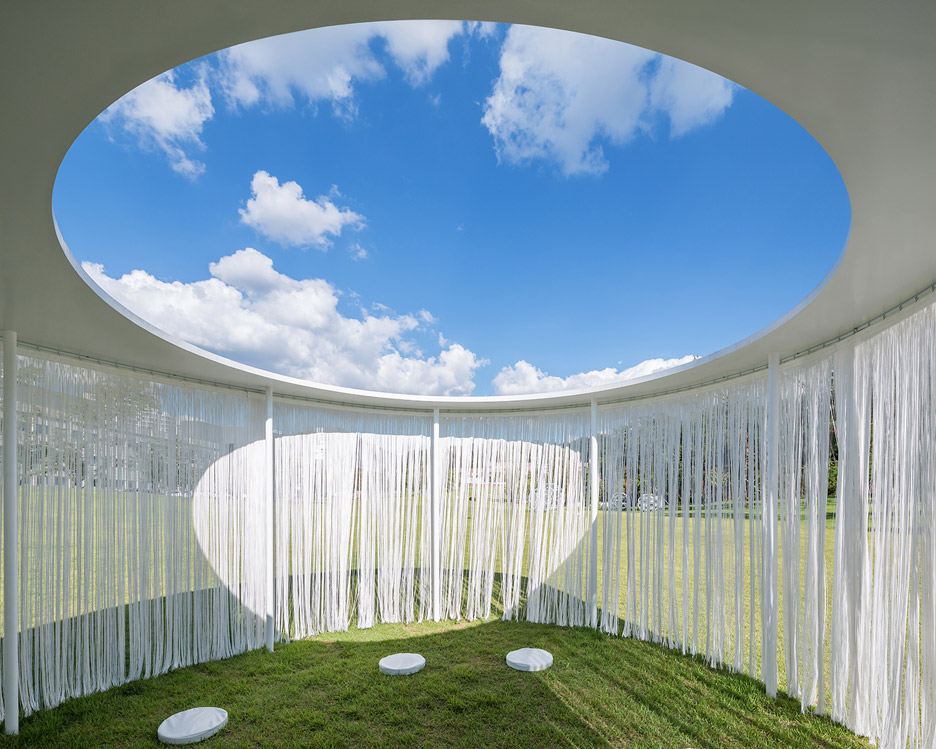
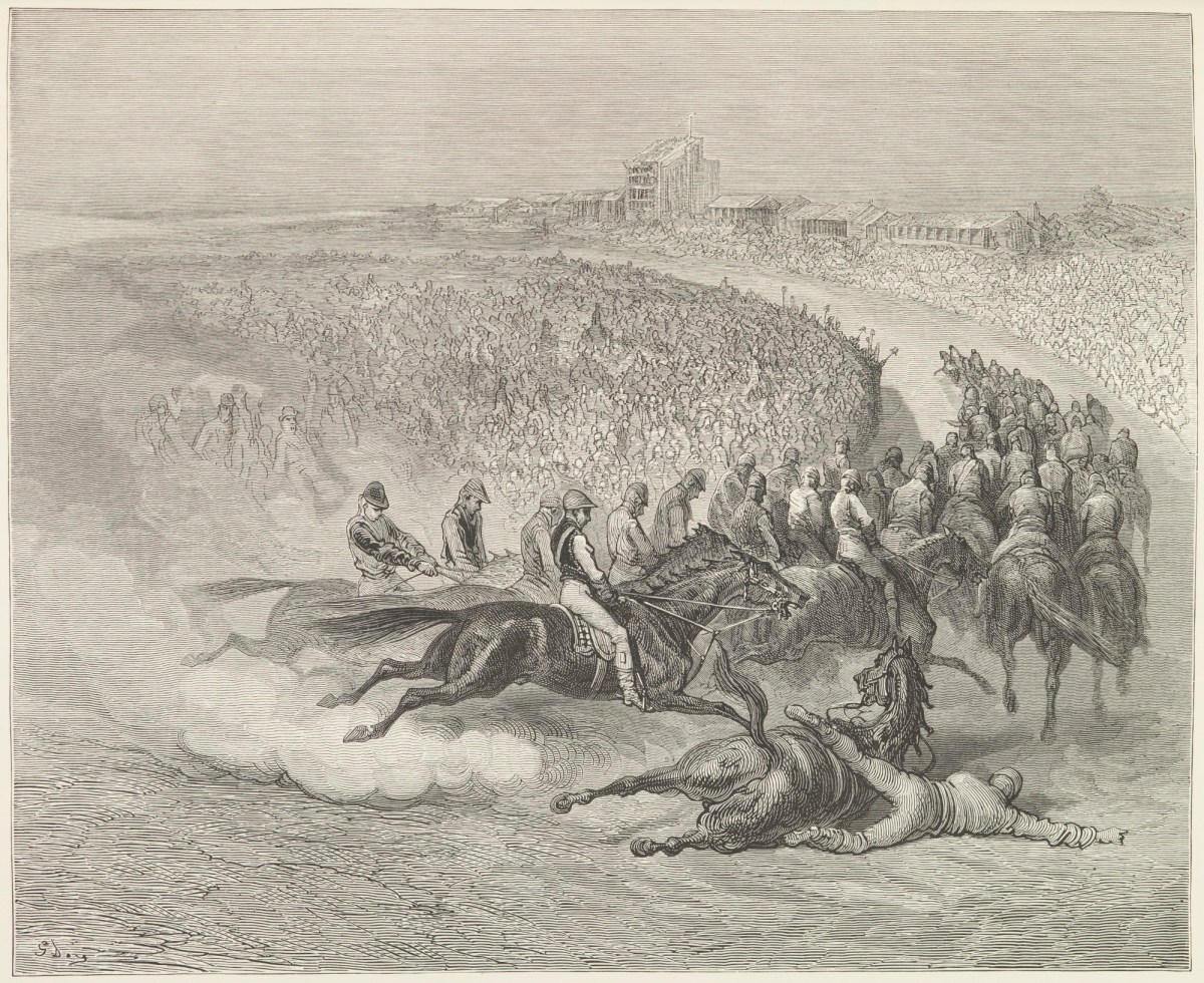
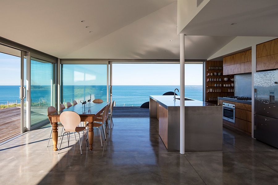
.jpg?1502945065)
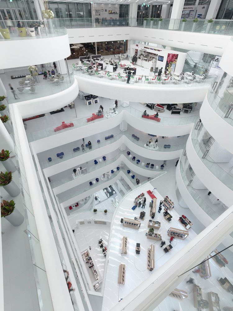
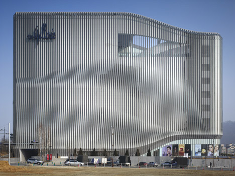
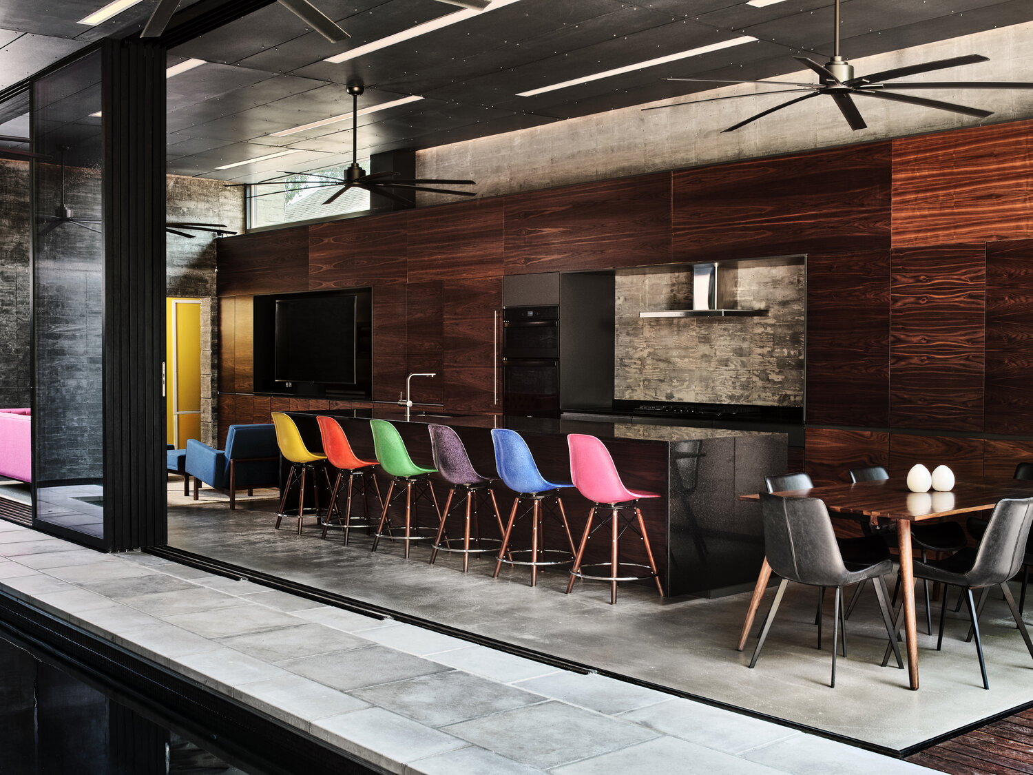
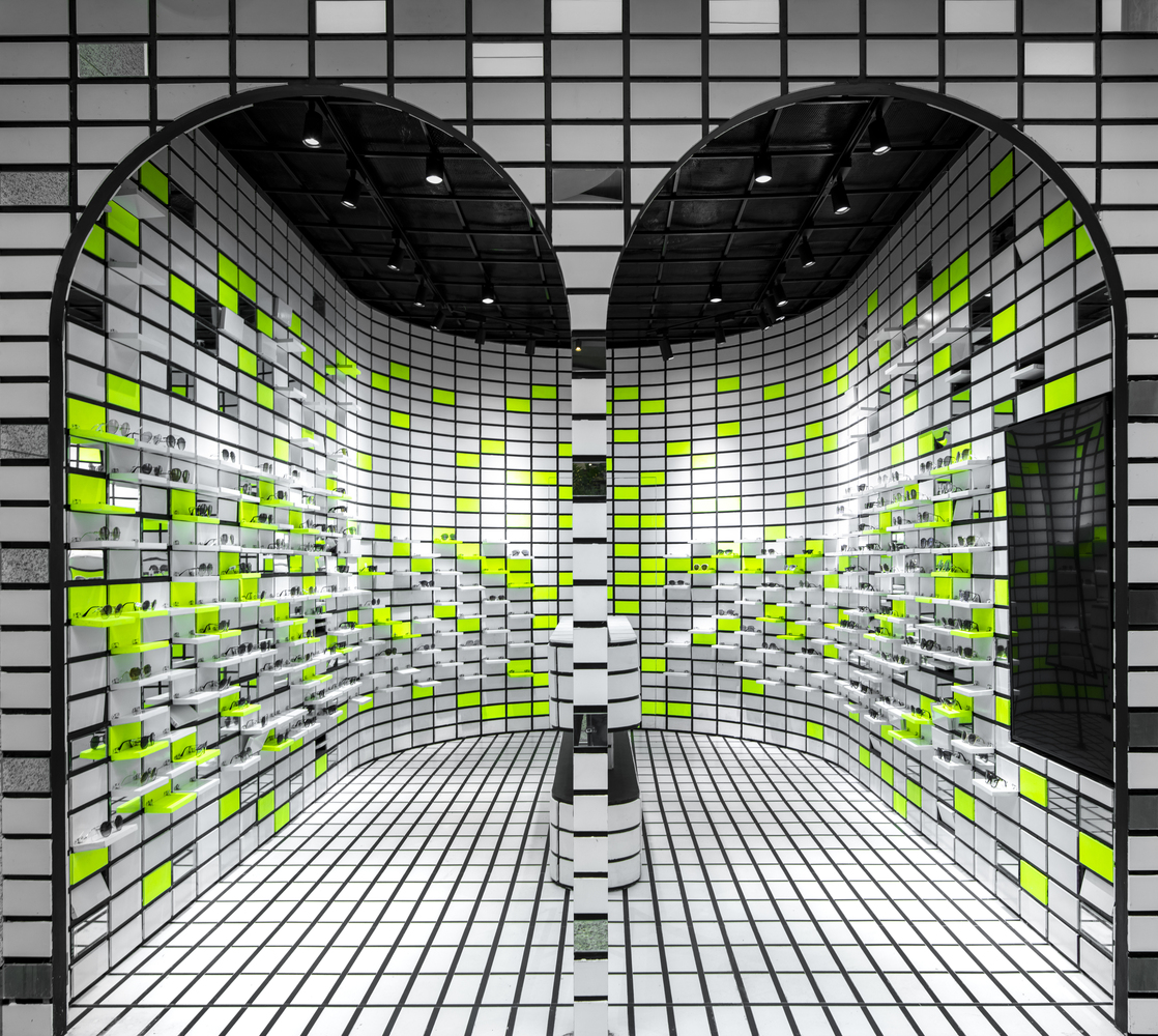
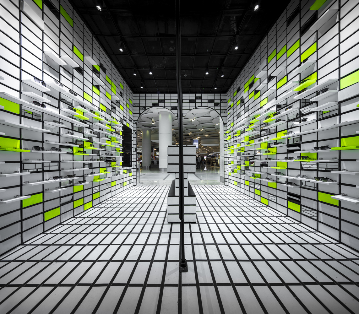
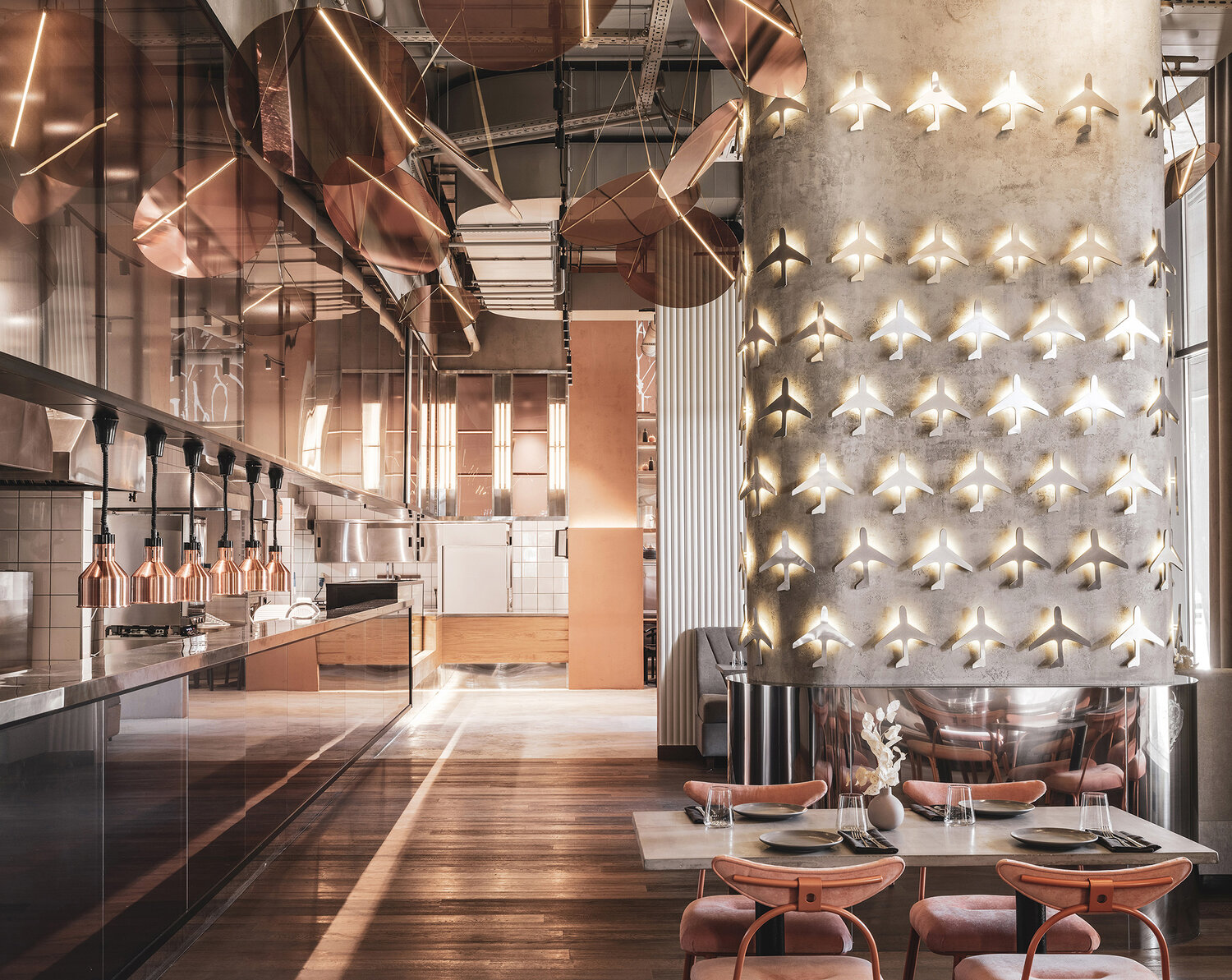
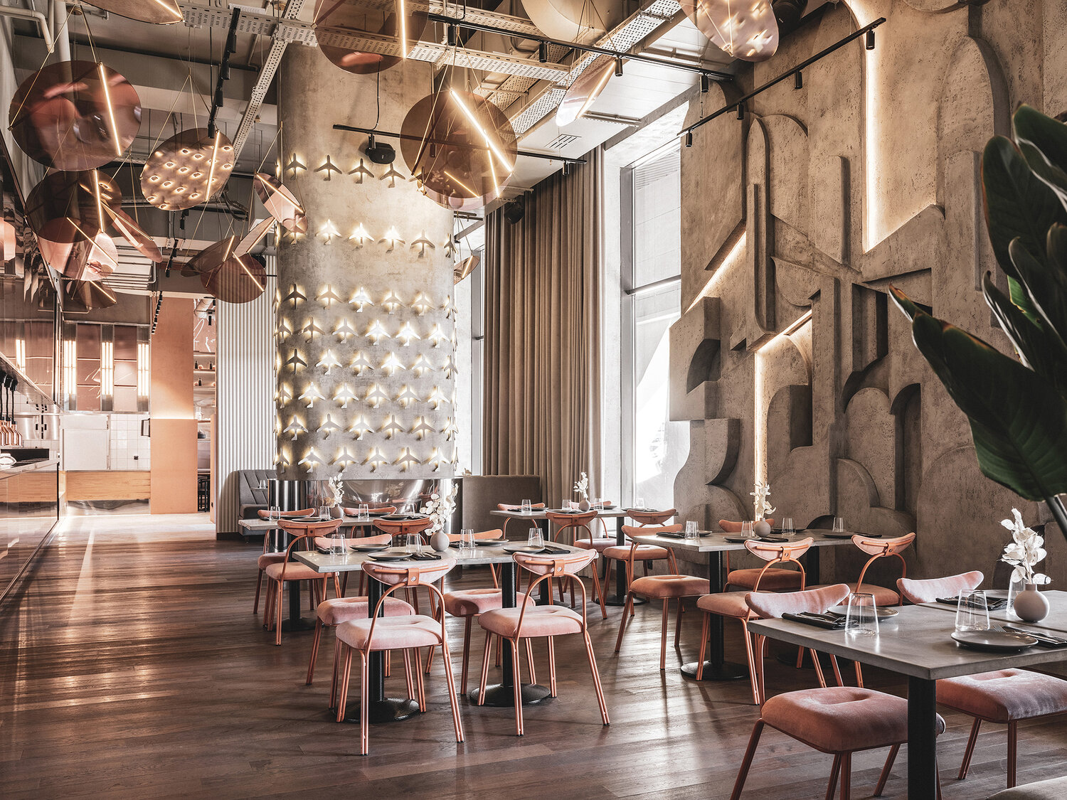
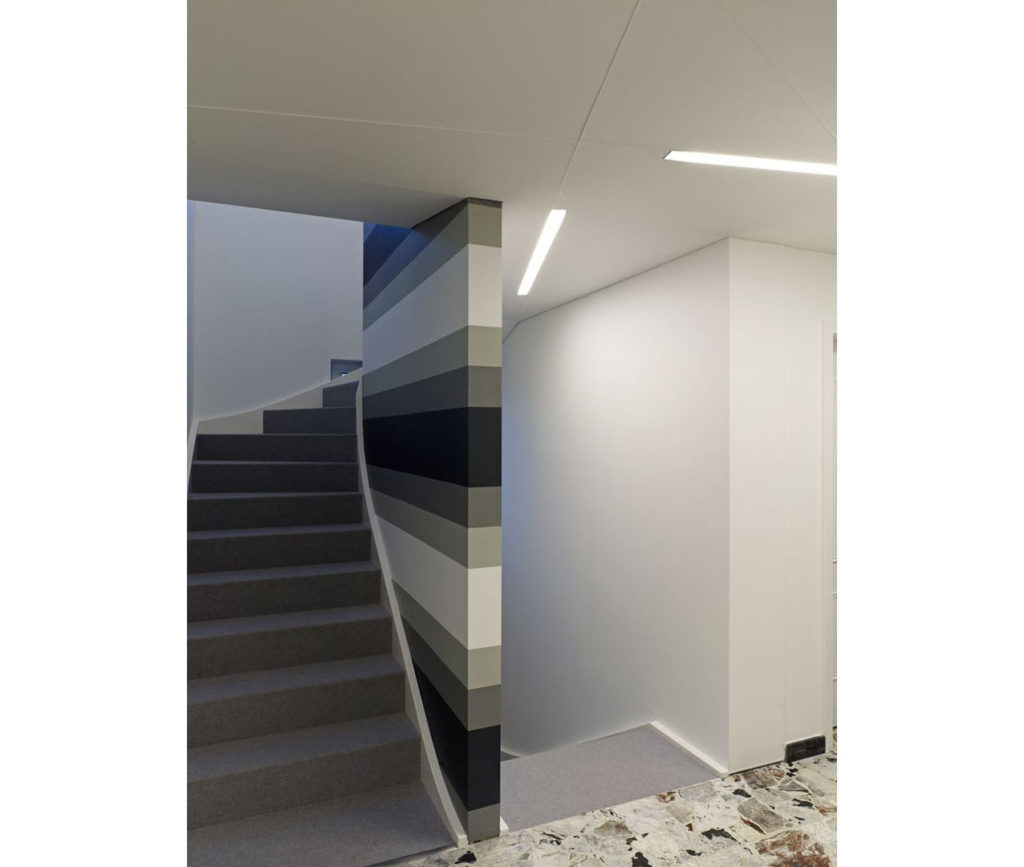
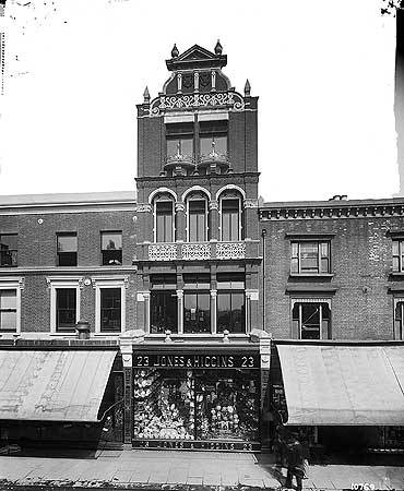
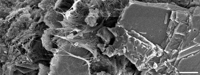