I received the feedback a while ago and needed to clarify a few bits with my tutor before properly reflecting on it. In the meantime, I got stuck in Part Four and finished it, so only now the time allows to type it out (I had notes for ages).
Overall:
My tutor noted that I am learning how to communicate through drawing, it is an essential tool and measured and accurate hand and CAD drawings are important.
My tutor clarified that drawings are part of instructions, and it is likely that my future drawings will be instructing ‘hand’, not the machine, therefore I should not worry too much about points size in my hand drawings as there always be ‘an amount of tolerance’.
According to the feedback I have done well with Contextual Study ‘Lines – a close reading’ by breaking the text down and then making connections. My tutor said my methods will pay off; it was reassuring to hear as I was not sure whether my mind map was done the ‘right way’. It paid off to do what felt right. Also, during our recent chat my tutor said there is no right or wrong way to do contextual studies, as it is all about what I think (that was rather wonderful news!)
My peer activity has been noted and encouraged – I shall continue.
Research:
It is nice to know that my research is considered thorough and in some cases I researched beyond the requirements of the course (I had not even realised I did ‘extra’). My tutor said that any extra work like that will help me with the studying and develop my unique design interests. I will continue drawing on my own experience when considering texts and drawing my own conclusions.
Creativity:
My approach to ‘Lines’ contextual study and completing it showed (according to the feedback) creativity. This helped me understand the ideas presented and draw my own conclusions. I am really pleased my tutor thought so as I found this task quite hard at the time (not creating but reading and understanding).
My tutor’s opinion is that my creativity shows in connections I make between the course work and the ‘outside’ world. I must make sure I take photos or draw and add these images when I make my observations in the learning log.
I am encouraged to share more of my thoughts, I must remember to take notes and photos or draw when they come to me.
I keep having thoughts about lines, that text really stuck in my mind. Previously in my learning log I said that only truly straight lines are rays of light, but I was wrong… A piece of string can be straight if its hanging with a weight attached to the bottom. In this case the gravity/ nature makes it straight, even if the string is manmade. This knowledge is often used by bricklayers as reference for building straight, vertical walls.
Another thought about straight lines is that perhaps it does not matter if the line is perfectly straight as long as it appears straight.
Communication and presentation:
I have received a well done for persevering with CAD software and on starting with technical drawing both in CAD and by hand.
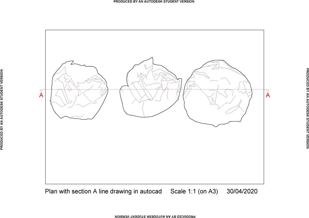
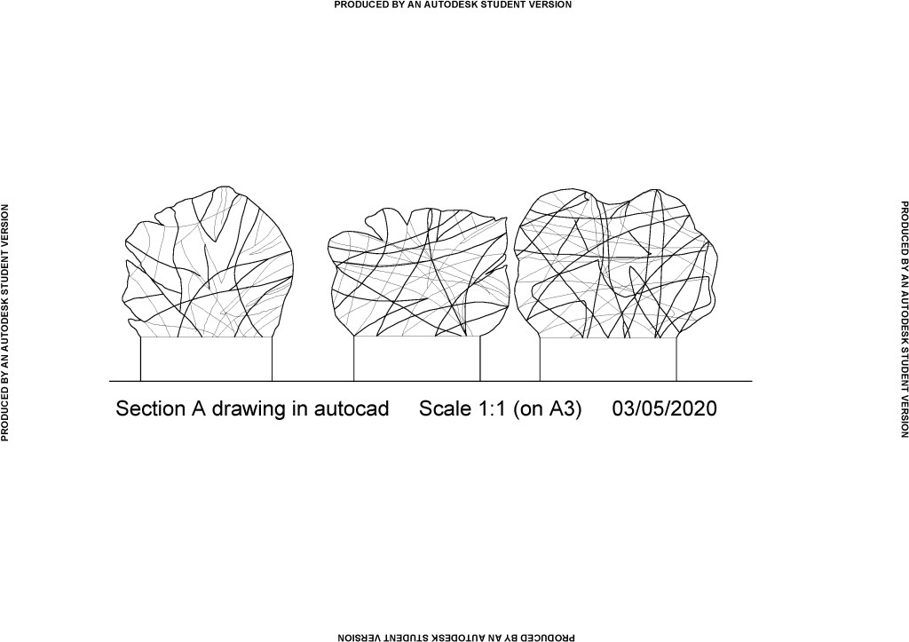
My tutor said that section drawn by hand (or line drawing in CAD, not a section of an extruded 3D shape), helps understand better individual components and how the section is made.
Drawing on a board with parallel motion was recommended by my tutor. I already got one and I am looking forward to the next technical drawing exercise where hopefully my angles will be better than in my previous exercises. It is important that my angles are what they should be, and the lines are parallel when needed. I realise I did not get it quite right in the past.
I should improve on using line weights to indicate the hierarchy in line drawings.
My tutor recommended checking the wall thicknesses in my bathroom drawings. I have since clarified it with her, that two walls are external hence they are thicker in my drawings.
I should research how other CAD drawings are titled and I should include title block and some dimensions in my CAD drawings.
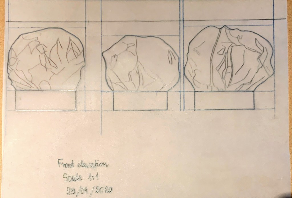
I also should have added thickness to the ‘cut’ card in section drawing of my model in assignment 3. Even though it is a card and is fairly thin I should have included that thickness in my CAD drawing. I tried to measure it since, and it looks like 0.1mm thickness. I had a look online and found a table on ZX Printer website stating that 140gsm paper which I used to create the base of my model has thickness of 0.16mm. Now I wonder whether the ‘cut through’ tops in my model should also have had thickness according to their 80gsm. According to that same table that would be 0.065mm thick. Therefore, CAD is such a great tool, it would be impossible to include this detail by hand (unless you do a magnified scale (eg. 10:1) drawing for a portion of ‘normal’ drawing.
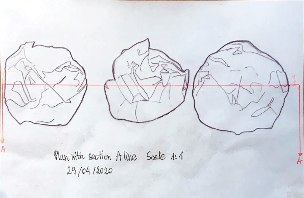
My tutor mentioned that it would have been a good idea to include bases of my model in plan as dotted line. What a great idea, I am gutted I did not think of it at a time.
Also, there was no need to copy my plan drawing to then add section, I should have done it on the original. I wanted to preserve my original drawing but there was no need for that.
My tutor said more information (within reason) such as section line on the drawing is better.
My tutor noted that ‘my survey notes for spatial drawing were well organised with different colours for different dimensions’ – I was pleased to read this compliment.
Critical Reflection:
My tutor told me that contextual studies and critical reflection tasks add to knowledge and eventually will help me inform my design choices and connections I make.
After reading the feedback I realised I had not been clear enough in my reflection in exercise 2.3 regarding my measurements not being clear to someone else. They were clear to me; I was instructing myself with them. Of course, I agree with my tutor that if I were passing those instructions on to someone else, I would need to make my notes super clear. I should practice ‘clear’ instructions for myself in the meantime so I am not out of my depth in future when I could possibly be a part of a larger team. Certainly, I must reflect in a clear and productive manner too.
To improve my work:
- I need to look at some examples of technical drawings, layout, how drawings relate to others on same page, what information is included in title block, how much other information (dimensions, notes, material) is given. Does this depend on the scale of the drawing?
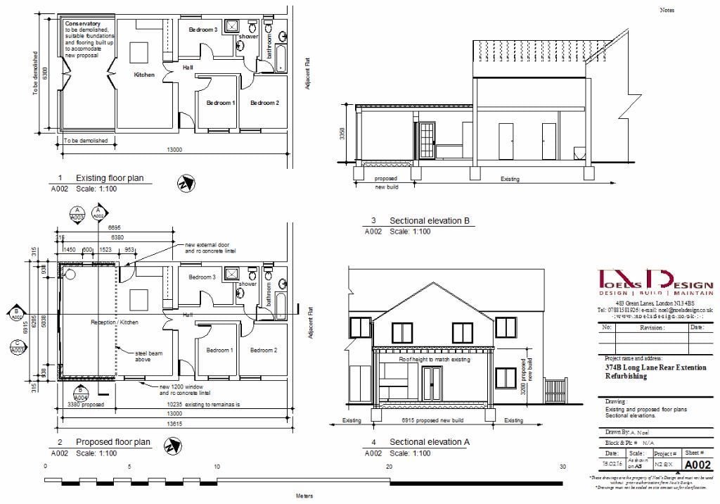
In Fig. 1 above we can see that each room is described with its function, there is a compass near floorplan showing North. Each of the subdrawings has a number and title underlined, and below sheet reference number and scale. Also, for reference there is a line scale added, which is a practical solution in case this drawing was not printed on a3, one could use a ruler and work out a scale. There is a lot of very clear notes what is to be kept, what to demolished, specific comments regarding new dimensions, new structural elements. I’m assuming title block is the one in bottom right corner, it includes: company details, a small table for revision comments (which is blank so I’m assuming it’s the first version), project details, drawing details (i.e. ‘existing and proposed floorplans, sectional elevations’), authors name, date, scale, project number and sheet number. There are some dimensions (as suggested by my tutor) and section lines. I also noticed that existing and proposed floorplans are directly above one another with walls on right hand side aligned so the difference in extension sizes on both plans can be seen. I can also see structural elements under the floor of the building. There is also some small print, possibly about terms and conditions, not quite legible
Noticing all this information made me think I should probably create a template table to include in my technical drawings so they all include same information and I should place it in one of the corners of my drawings.
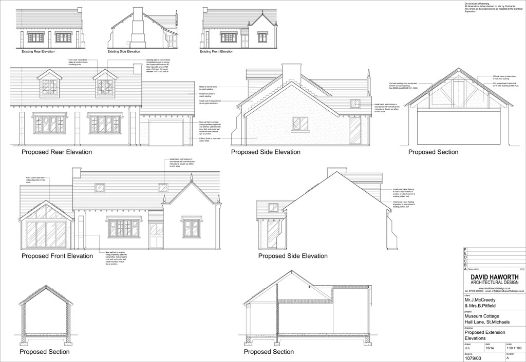
The drawing in Fig. 2 contains a lot of instructions for the builder (architect ‘rules’ the builder – lines again). It does not specify any dimensions. I can see that subtitles under each part is scaled to match scale of the drawing. There are two scales specified, but it does not say on what paper, so I assume architect would print this one on the correct size paper and provide hard copy to the contractor. There is a comment saying ‘not to scale off the drawing’, perhaps there was more drawings in the pack specifying the dimensions in detail. There is a similar table to Fig. 1 containing similar information.
Both drawings look neat and clear. I must look at some tutorials how to create and paste information tables into my drawings.
- I should remember about thicknesses in section drawings, no matter how small.
- I need to pay more attention to line thicknesses and their hierarchy in technical drawings.
- My tutor recommended that I practice technical drawing of objects and spaces known to me either by hand or in cad.
- Books and websites were suggested to broaden my knowledge. I signed up to the mailing list on https://www.drawingmatter.org/ to receive their newsletter straight to my inbox.
All in all, I am pleased with my feedback and the amount of advice and tips I got from it.
List of illustrations:
Fig. 1 Noel, A (2016) Existing and proposed floorplans. Sectional elevations. [CAD Drawing] At: https://quickmarket.co.uk/wp-content/uploads/2018/08/4-537.jpg (Accessed 19/06/2020)
Fig. 2 Haworth, D (2014) Proposed Extension Elevations [CAD Drawing] At: http://www.davidhaworthdesign.co.uk/wp-content/uploads/2015/03/c.jpg
References:
ZX Printer (2013) The Thickness of Printing Paper List [Reference Table] At: https://www.zxprinter.com/support/paper-thickness.html (Accessed on 19/06/2020)
